Final Project

List of Contents:
Introduction
I was greatly inspired after watching the TED Talk about Digital Farming, delivered by the director of MIT’s Open Agriculture Initiative, Caleb Harper, which came up with the topic: This Computer will Grow your Food in the Future. The most important question addressed in his talk that really inspired me was What if we could grow delicious, nutrient-dense food, indoors anywhere in the world? And here the idea was born!
So, what I am trying to do is something like a box or incubator, which is able to create ideal climate conditions necessary for growth, providing exactly the amount of light and nutrients that a plant needs. I want to build a sunlight emulator, irrigation system, and climate controller wrapped into one elegant and modern design.

I am planning to achieve the desired results by implementing the following technology:
Grow LED light - the Chlorophyll in plants primarily responds to only two wavelengths, represented by 450nm & 650nm. The LED system which I am planning to use will have a combination of red and blue LED lights to provide the perfect blend to help in both vegetative and flowering growth.
Ultrasonic Atomizer (fog maker) - I want to use a new method of irrigation, which I found out for myself recently, called aeroponics (FogPonics) that waters the plants through fertilizer-infused mist.
Automatic Nutrient Dosing - This system will automatically dose the nutrients for plants exactly when they need it.
Water Sensing System - I want to equippe my system with pH and TDS (Total Dissolved Solids) sensors to help maintain a balanced pH value in the water reservoir that will suit best for plants as well as knowing and alerting when to dose the nutrients.
Water Exchange System - the system should be equipped with a hookup for automatic water changes. I want to make this process easy, and controlled just by the click of a button.
Air Control System - It allows having a precise control over temperature and humidity inside the system, down to a single degree. The technology behind involves the use of a Temperature/Humidity sensor like DHT22 or DHT11 to receive the data, and a fan with a coil to regulate it accordingly.
Mobile App - I really want to build an App for the first time in my life! This app should include real time information about the pH level, temperature, humidity, nutrients, ppm etc. and a graph representation over time in order to track statistics and share the growth progress on social media. I also want to implement intelligent alerts that will let me know when the system needs my implication. I also want not only to receive the data representation on my phone, but also be able to setup the climate conditions inside the system!
Unfortunately, I am not the first one who came up with this kind of idea, but the best way to come up with a creative idea is to improve the existing ones!
There are several similar projects on the market available, however, despite all the individual advantages, they have also some disadvantages like taking too much space or being too small, too expensive, growing only one crop at a time etc. I did a lot of research and analyzed carefully the strengths and weaknesses of the available projects, and considering the market response, I want to come up with a new advanced open source system, which will reduced the disadvantages and will implement only the best features.
Very ambitious, isn't it? But let's give it a shot
Experiments
Dealing with plants is very time consuming! They usually require from several weeks to several months to grow, and I have to be ready for that!
Because I know already what I want to build for my final project, I have to take care of it in advance and not leave everything for the last moment. That is why, I will start testing and experimenting as soon as possible!
First thing which I want to find out, is the fact that growing plants using nutrient rich mist and grow LED lights is better than a conventional system in soil and natural sunlight! In theory, this should be exactly the case, but I do not believe anything until I try it!
So I decided to start my own experiment, which will require some time, and it consists of deviding the plants into several groups:
(Soil + Sunlight) - this group will grow in absolutely natural conditions, planted in soil, and placed on the windowsill.
(Fog + Sunlight) - this group will be placed in a container, which will have nutrient rich mist inside, and also placed on the same windowsill
(Soil + Grow LED light) - this group will be in soil, but will use artificial Grow LED light instead of the sunlight
(Fog + Grow LED light) - this is supposed to be the HERO group) Because my future system will implement these two features, the grow LED light and the nutrient rich cloud of fog, I hope to find out that this combination will show the best results!
In the local german store Kaufland, in the plants department, I bought the seeds of mixed herbs. These will be my testing babies :p


It was the first time in my life when I planted anything :D do not judge me if I did something wrong!)
I checked several tutorials before, and I learned that I have to germinate the seeds first. I got a plastic container, where I placed the seeds, and covered them in a paper towel. At this stage, they need almost 100% humidity, that is why I used a spray to water the paper towels, and covered the container with the plastic bag, so the water does not evaporate.

I left the seeds for 1.5 weeks, and when I opened the container, I was really surprised!

Almost all the seeds germinated! I was happy like a kid)
Next I had to select the best little plants, the ones that had the thickest stem, and just looked bigger and better overall.

In the tutorial that I was following (YouTube blogger), the guy recommended to plant the little plants into any type of medium, until they give so called "second leaves". On Amazon I ordered coconut coir pellets. They are organic, have similar properties to soil, and the cool thing is when the pellets are watered, they become x6 times bigger in size.
I also purchased a box, which has separators specially for planting! I got it for only 2 euros, and this made the things way more organized. I placed the coconut pellets inside the separators of the box, watered them until they became fully hydrated, placed the little plants in the middle, and covered the box with a transparent piece of plastic which came with the box kit.
My little greenhouse looked like this:

I closed the box, and left it for one week!
And again when I opened it, I was surprised! They actually became bigger! I could never imagine that I can manage to grow some plants, I barely manage to take care of myself :D

After one week, the difference is noticeable!
Now when I see the first roots, I can place them in soil and clay balls, and start experimenting with fog!


During the Computer-Aided Design week, I designed the net cups, which I used to place the plants

I also bought in a local store a plastic container with the aproximate dimensions which I need, and sketched the holes to dril!

And here is my assembled test system, with the plants inside the coconut pellets, and clayballs, as well as soil!

To be honest, the results could be better :D
Only few plants survived in my fog system. My guess is because of the growing medium! The fog is not strong enough to keep the clay balls wet, neither the soil.
Easter Break!
During the Easter break I did not do anything, and because the lab was closed, all the system was off as well. So, my plants all died
With a fresh mind, I desided to make another system, but this time using another growing medium based on the previous observations
The growing medium which I chose for this system is Rock Wool. I bought it in our local IKEA store. I also bought a couple of seeds from their department

And I placed the new seeds into the rock wool for germination for one week!

After one week I checked my box, and noticed that one type of seeds were successful, another failed! Due to the lack of time, I went on with the seeds that germinated

In the meanwhile, I set up another fog system, and will try to encrease its working time, to see If I can germinate seeds using fog, ONLY FOG!
I will keep experimenting with different parameters and settings, and see how far I can reach!)
Electronics Design & Production
Before jumping on designing the final board, I sat down to draw on a piece of paper all the features and requirements which the board must implement and fulfil! I also keep track of how many pins are going to be used, in order to estimate better and decide which will be the final microprocessor
Here is the sketch of what should be on the board:

The final choice on which board to use was between satshakit from Daniele Ingrassia and FABLEO by Jonathan Grinham
satshakit is a 100% Arduino IDE and libraries compatible, fabbable and open source board, and also an improved version of Fabkit.
Main improvements and features over Fabkit are:
- 16Mhz instead of 8Mhz
- crystal instead of resonator
- costs less (7-9 euro vs 13 euro)
- 100% compatible with default Arduino IDE (satshakit is recognized as Arduino UNO)
- ADC6/7 connected instead of ADC6/7 not connected (satshakit laser and cnc)
- larger space to easy soldering (satshakit laser and cnc)
On the other hand, the FabLeo has very similar features, plus the hardware USB! Because I used already the ATmega328p earlier, I wanted to try something new, and decided to use the FabLeo design as my starting point
My bible and #1 guide for this assigment was the ATmega32u4 pinout

To design the board, the software which I will be using for this is 
EAGLE (Easily Applicable Graphical Layout Editor) is a flexible and expandable EDA schematic capture, PCB layout, autorouter and CAM program. EAGLE is popular among hobbyists because of its freeware license and rich availability of component libraries on the web.
Eagle has two windows that are used simultaneously to design a board:
- Schematic (.sch) - logical components
- Board Layout (.brd) for the actual board that we mill
After I installed EAGLE, the first thing which I want to do is Create a New Schematic. A schematic in electronics is a drawing representing a circuit. It uses symbols to represent real-world electronic components. The most basic symbol is a simple conductor (traces), shown simply as a line. If wires connect in a diagram, they are shown with a dot at the intersection.
In order to place my components on the schematics, I have to download and use special Libraries. Eagle has a lot of built in libraries of components that we can use. The fab network also maintains a library which is constantly updated:
In order to install the library, in the EAGLE environment, go to the top toolbar and select the Library menu. Then select use and open the .lbr file that I just downloaded.
Now I can go to Add component and selecting the library, I choose the component which I want to place.
When I have all the components placed on my schematics, I have to connect each of them to the pins of the microprocessor. In the EAGLE left menu, I click on Net, command which allows me to draw green lines and connect the pins. Important thing is to start the connection from the little line on the pin (I marked it on the picture)

To avoid multiple connections, I will be using Labels.. In EAGLE left menu, I press Add Label and add it to the end of my connection line. If I press the right click and then choose name, I can attribute to the label the same name which I used for the microprocessor pin, and connect them in this way!
If I did everything right, a message should appear that states: Are you sure you want to connect your label (N$10) with GND?

At this stage, in the chematics, the important thing is the Logic of all connections, not the way it looks. After I finished placing all the components, and connected them in a logical way, this is how it looks:

I added the AVRISP pinheaders, and placed them in according order for the connector. These pins will be used to program my board.

Here is the schematics of the USB circuit together with the crystal

I also added a Voltage Regulator circuit which will power the whole board by transforming the input 12V into 5V

One of the important features of this board is the MOSFET circuits, I added 4 of them, 3 connected directly to the input (12V), and one will be connected to a step-up voltage regulator. The last will be used to power the fog which works at 24V

After I double check all the connections, I can proceed to the next step, which is the Board Layout. On the top menu, I press Generate/Switch to Board.
First thing which I do is increase the Grid resolution. I go to Viewmenu, and press on Grid, and change the values to 0.01. This will let me be more precise while drawing the route lines.

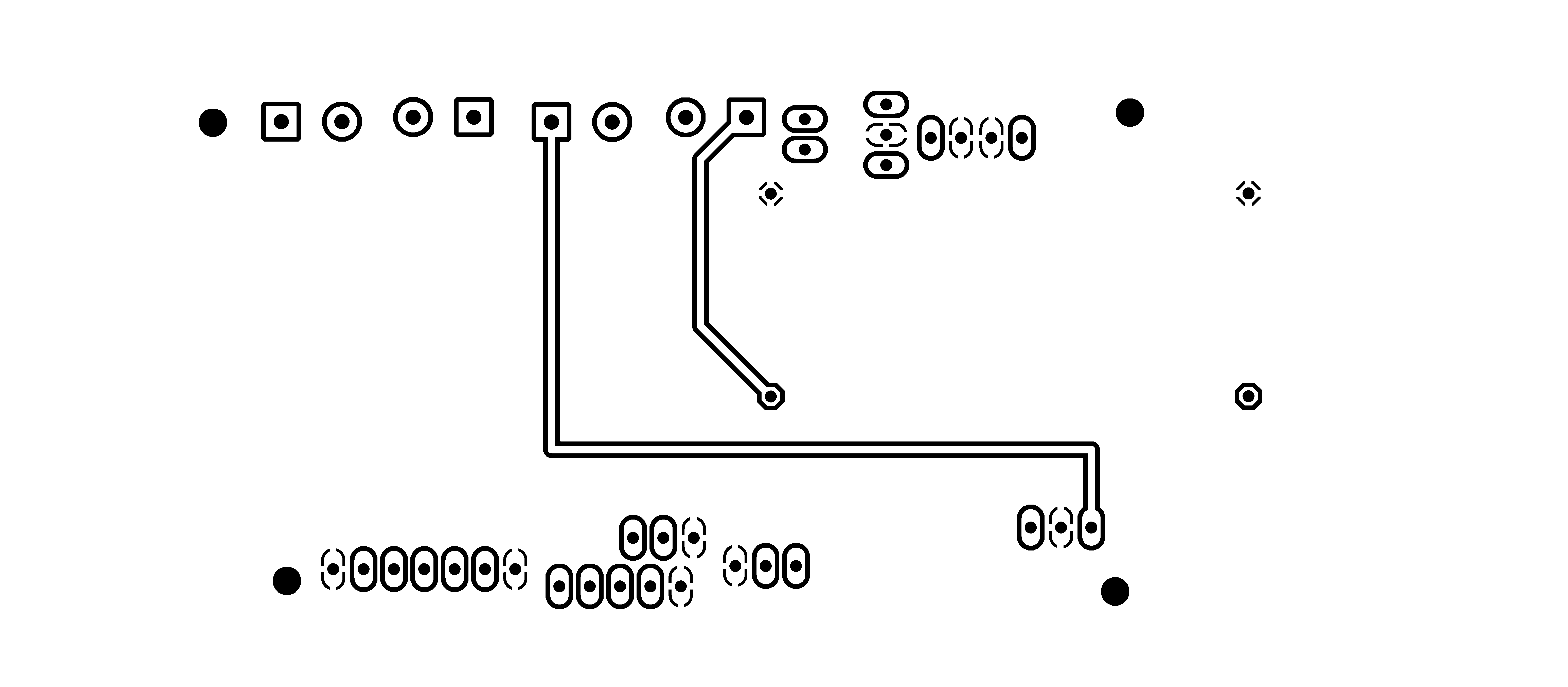
Surpisingly, the routing of the most complex board which I have made so far was also the fastest!) I am proud of myself. The experience of making boards had a good influence on improving the speed. After I was done routing, this is how the little beast looks:

For this board I am using also the trick which I learned earlier. I draw a polygon around my components, and by pressing the right click on the polygon line, I change the name to GND. This will fill the whole area inside the polygon, and make it to be the GND.
This will save a lot of time, space, and effort
When I double check everything, I can Export my file as a .png picture.
In the appearing window, I increase the resolution to 1500 dpi, click on monochrome, and select window mode.

To edit the .png image, I will be using  I open my image in GIMP, and using the
 rectangular select tool, I select the image leaving some space from all the sides. After I press File and Copy the selected area. To continue working with the selected picture, I click again on File, and Create from the Clipboard
This is what I get after all the editings:

This image is ready to be printed, and I will call it Inside_Cut
I prepare the process for the Outside Cut, and this is what I get:

Because my board is double sided, I have to mill two pieces, and then glue them together. The only thing to keep in mind is that the bottom part, has to be mirrored horizontaly
Bottom part Inside_Cut

Bottom part Outside_Cut
Now I can proceed to the CNC milling machine. So, again I used FabModules to convert the .PNG files into Gcodes for the Roland machine.
Let’s start to work with the Fab Modules. When I introduce the ip adress into the browser window, the first interface that will appear is:

After I press on th gray button input format, a new menu should appear with the option to load the .PNG image. Here I upload the first image, which is the inside engraving. After doing that, the preview of the image will appear in the Fab Modules and also other fields and other parameters will show up
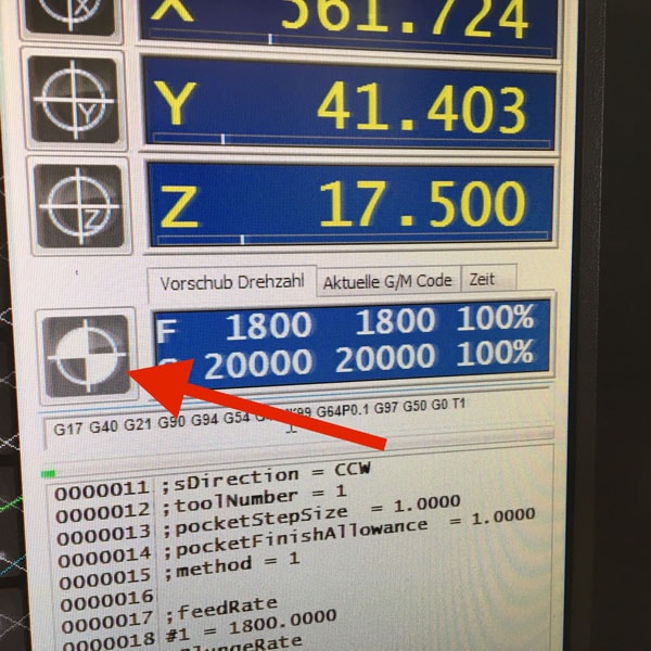
On the right side of the window, we have many input parameters. In order to be able to move the machine, we have to input the following parameters:

mod_lp.py /dev/usb/lp0 into the send command field
hostname_of_your_machine into the server field (just the address without http or /)
In order to move the machine I just enter in the respective fields the x, y and z position coordinates. Before moving the machine I have to make sure that the zjog parameter is always set to 0, even if it will change automatically. To move the machine I have to press the move to xyz0 button.
* A small life hack is to use the multimeter and check if there is connection between the tool and the surface. As a tool to engrave PCB is suggested to use diameter from 0.2 mm and below, while for cutting we can use a 1 mm tool.

So my final settings look like this:

For the outside cut the settings remain the same with the exception of the value of the Z-Axis, as I replaced the 0.2mm tool with the 1mm tool. This is how it looks:

Repeat the same process for the Bottom part and mill the Inside and the Outside parts:


This is the final result for the Top part:

And the Bottom part:

And now Let's solder this!
In order to make sure that I soldered everything in a right way, after each component soldered, I used the multimeter to check if there is conductivity between the component and the traces.
Short animation of the process:

When I plugged in the PCB board to check if everything is fine, I noticed an error. From experience, I know that the error was from a short circuit, because the computer was disconecting the Arduino all the time I connect the VCC and GND to it. So my guess was that somewhere on the board VCC and GND are connected, and using the multimeter, I confirmed that I was right.
It was late, and I got so f*ckin' mad because of that, took me one hour under the microscope to find that little mistake. Here it is:


I fixed it by scratching with a knife, and increasing the isolation!
Another thing is placing the Step Up Voltage Reguator on the back side of my board.


I measured the dimensions in advance, and designed predrilled holes to fix it with the pinheaders. But before soldering it on the back side, I have to calibrate it.
The idea is that when I power the board with 12V, the step up will output 24V necessary for the Ultrasonic Atomizer, which is connected to the MOSFET circuit
I used the bench power supply, with a fixed 12V, to measure the output voltage using a multimeter.

After I adjust the output to the one that I need, 24V in my case, I can solder it to the back side of my board!
Also on the back side, I placed the WiFi board which I made during the Networking and Communications week!
So, here is The BEAST:


A HERO picture for those who may think that it was easy, and everything went smooth :D

Download Files:
Wiring & Embedded programming (I/O Devices)
To program my board I used Arduino IDE. I connect the arduino board to the USB hub, in the tools menu select the right board (Arduino Leonardo) and the port, after go to File--> examplesand open the Arduino as ISP sketch. Upload the code.

After I see done uploading, which means that the code is uploaded to the board, I disconnect the arduino from the PC. The next step is to connect my PCB board to Arduino using some wires. The connection scheme is this one:
- SCLK: Serial Clock (output from master) ----------> Arduino Pin 13
- MOSI: Master Output Slave Input ----------> Arduino Pin 11
- MISO: Master Input Slave Output ----------> Arduino Pin 12
- VCC: Positive supply voltage ----------> Arduino VCC
- GND: Ground ----------> Arduino GND
- RST: ----------> Arduino Pin 10

I connect the arduino board to the USB hub. Under Tools select the right board, select Arduino as ISP programmer, double check the parameters, and press the Burn Bootloader button.
And I see Done Uploading! Good sign)
To test the board, I upload the basic Blink example code:
Ohh, I LOVE that BLINK :D Now let's go to sensors!
First sensor that I want to use is DHT11 - Temperature & Humidity Sensor

These sensors are very basic and slow, but are great for hobbyists who want to do some basic data logging. The DHT sensors are made of two parts, a capacitive humidity sensor and a thermistor. There is also a very basic chip inside that does some analog to digital conversion and spits out a digital signal with the temperature and humidity. The digital signal is fairly easy to read using any microcontroller.
Some characteristics:
- Ultra low cost
- 3 to 5V power and I/O
- 2.5mA max current use during conversion (while requesting data)
- Good for 20-80% humidity readings with 5% accuracy
- Good for 0-50°C temperature readings ±2°C accuracy
- No more than 1 Hz sampling rate (once every second)
- Body size 15.5mm x 12mm x 5.5mm
- 4 pins with 0.1" spacing
The wiring is pretty easy, just VCC, GND, and any Digital Pin! In my case, I designed in advance the connection for this sensor.
To test it, I will upload a simple sketch. The sketch includes the library DHT.h
So here is the code:
// DHT11 Temperature and Humidity Sensors Example

#include "DHT.h"         //include DHT library

#define DHTPIN 2         //define as DHTPIN the Pin 2 used to connect the Sensor
#define DHTTYPE DHT11    //define the sensor used(DHT11)

DHT dht(DHTPIN, DHTTYPE); //create an instance of DHT

void setup() {
  Serial.begin(9600);    //initialize the Serial communication

  dht.begin();           //initialize the Serial communication
}

void loop() {

  float h = dht.readHumidity();    // reading Humidity
  float t = dht.readTemperature(); // read Temperature as Celsius (the default)

  Serial.print("Temperature = ");
  Serial.println(t, 2);    //print the temperature
  Serial.print("Humidity = ");;
  Serial.println(h, 2);  //print the humidity
  delay(2000);           //wait 2 seconds

}
When I open the Serial Monitor, this is what I get:

Another sensor which I want to use is DS18B20 - One Wire Digital Temperature Sensor

DS18B20 is 1-Wire digital temperature sensor from Maxim IC. Reports degrees in Celsius with 9 to 12-bit precision, from -55 to 125 (+/-0.5). Each sensor has a unique 64-Bit Serial number etched into it - allows for a huge number of sensors to be used on one data bus.
This is by far one of the most simple digital sensors to hookup. Aside from power and ground, it has a single digital signal pin that I will be connecting to digital pin which I designed in advance. It also requires a 4.7k pull-up resistor between the signal and power pin, which unfortunately I forgot to place on my PCB. That is why, I will solder it manually directly to the sensor cables.
Before I start, I have to download the libraries: OneWire.h and DallasTemperature.h
Upload the following sketch:
// First we include the libraries
#include <OneWire.h>
#include <DallasTemperature.h>

#define ONE_WIRE_BUS 3

// Setup a oneWire instance to communicate with any OneWire devices, (not just Maxim/Dallas temperature ICs)
OneWire oneWire(ONE_WIRE_BUS);

// Pass our oneWire reference to Dallas Temperature.
DallasTemperature sensors(&oneWire);


void setup(void)
{
 // start serial port
 Serial.begin(9600);
 sensors.begin();
}


void loop(void)
{
 // call sensors.requestTemperatures() to issue a global temperature (request to all devices on the bus)
sensors.requestTemperatures(); // Send the command to get temperature readings

 Serial.print("Temperature is: ");
 Serial.print(sensors.getTempCByIndex(0));  //You can have more than one DS18B20 on the same bus. 0 refers to the first IC on the wire
   delay(1000);
}
The funny thing is that after I successfully programmed the sensor, It stopped working while I was integrating all the sensors together! I spend quite a long time trying to figure out why it does not work, but due to the limited time, I decided to use another DS18B20 sensor which was available in our FabLab stock, and waterproof it by myself!

So I took the sensor, and used the datasheet to properly solder the cables, and isolate them from each other using shrink tubes

I guess you have got the idea how I am going to waterproof it, right? :D Mama ama engineer!
Said - DONE!

Yeah, I know what it looks like :D but I assure you, its just a hand waterproof sensor. The most important is that it works, and does not leak when submerged in water!
And we go to the next sensor which is LDR = Light Dependent Resistor

LDR is a passive electronic component, basically a resistor which has a resistance that varies depending of the light intensity. The resistance is very high in darkness, almost high as 1MΩ but when there is light that falls on the LDR, the resistance is falling down to a few KΩ (10-20kΩ @ 10 lux, 2-4kOmega; @ 100 lux) depending on the model.
The LDR gives out an analog voltage when connected to Vcc (5V), which varies in magnitude in direct proportion to the input light intensity on it. That is, the greater the intensity of light, the greater the corresponding voltage from the LDR will be. Since the LDR gives out an analog voltage, it is connected to the analog input pin on the Arduino. The Arduino, with its built-in ADC (Analog to Digital Converter), then converts the analog voltage (from 0-5V) into a digital value in the range of (0-1023). When there is sufficient light in its environment or on its surface, the converted digital values read from the LDR through the Arduino will be in the range of 800-1023.
Here is the sketch code to test the sensor:
int sensorPin = A0; /*  select the input pin for LDR */
int sensorValue = 0; /*  variable to store the value coming from the sensor */


void setup(void)
{

 Serial.begin(9600);  /* start serial port */

}


void loop(void)
{

sensorValue = analogRead(sensorPin); // read the value from the sensor

 // We'll have a few threshholds, qualitatively determined

  Serial.print("LDR Value = ");
  Serial.print(sensorValue);

  if (sensorValue < 100) {
    Serial.println(" (Dark)");
  } else if (sensorValue < 200) {
    Serial.println(" (Dim)");
  } else if (sensorValue < 500) {
    Serial.println(" (Light)");
  } else if (sensorValue < 800) {
    Serial.println(" (Bright)");
  } else {
    Serial.println(" (Very bright)");
  }

   delay(3000);
}
Next is Water Level Sensor
I want to have a water level sensor in order to receive an alarm when the water container is empty, and its time to add some water. Because I did not think about it in advance, and we did not have any water level sensor in our stock, I decided that I can make my own water sensor!

I decided to use the materials available, in my case the Soil Moisture Sensor. The basic principle of the water level sensor is to measure electric conductivity, which is the same for the soil moisture sensor. I thought that If I can calibrate the sensor in a way that will fulfil my requirements, I can use the moisture sensor like an water level sensor) In principle, this is an analog sensor and the data that we will read will be values from 0 to 1024, and the rest is just math!
But as it often happens, the reality is slightly different. When the sensor is not in touch with the water, the analog value is 0, and when I submerge only the tip, the value goes to 800. I used the following sketch to read the values:
/* Print values from analog pin A4 to serial monitor */


void setup()
{
	Serial.begin(9600);

}

void loop()
{
	Serial.println(analogRead(A4));
	delay(100);
}
After I can read the values, I calibrated the sensor to give out three different responses: EMPTY! - when the value is 0, LOW when the values are around 800, and Full when the values are more than 900!
Graphic LCD Display

Because usually the LCD displays use a lot of pins, I had to find a way to connect the 128×64 screen in another way, and I DID!!! This way alows using only 3 Digital Pins on the board which is awesome because I may need the rest of the pins for other stuff, and it does not create a mess of wires. I premade the pins for the LCD on my PCB, and this is how I connected everything:

After I connect the LCD, It's time to programm it!
First of all, I have to download the U8glib library from HERE. Another important thing is the declared pins used in the code. The one I used are the following: U8GLIB_ST7920_128X64 u8g(4, 12, 6, U8G_PIN_NONE)
Using the "HELLO WORLD" library example, I came up with this test code:
#include "U8glib.h"

U8GLIB_ST7920_128X64 u8g(4, 12, 6, U8G_PIN_NONE);

void draw(void) {
  // graphic commands to redraw the complete screen should be placed here
  u8g.setFont(u8g_font_unifont);
  u8g.setPrintPos(0, 20);
  // call procedure from base class, http://arduino.cc/en/Serial/Print
  u8g.print("GIY Project v1.0!");
}

void setup(void) {
  // flip screen, if required
  // u8g.setRot180();
}

void loop(void) {
  // picture loop
  u8g.firstPage();
  do {
    draw();
  } while( u8g.nextPage() );

  // rebuild the picture after some delay
  delay(500);
}
And this is what I get:

One cool idea that came to my mind was to display the FabLab logo for some seconds, all the time when the display is powered. I spent quite a lot of time on doing this, but I finally did it! In order to display it on the Graphic LCD, I had to have a (.bmp) format picture, and display it as a bitmap.
First thing which I did was download the FabLab logo from the internet as a (.png) file, and reduce it significantly in size, so it fits my small LCD borders. I used the following online service to do that: LINK
These are the configurations I used:

The next step is to convert my small picture into (.bmp) format. I used the following online service to do that: LINK
Now, after I have my (.bmp) file, in order to place it into my code, I have to convert it into HEX array. I used a nice tool called LCD Assistant. To load up an image in LCD Assistant, go to File > Load Image. A preview of the image should open up, make sure it’s the right size – 128 pixels wide, 64 pixels tall. Also make sure the Byte orientation is set to Horizontal and the Size endianness is set to Little. These are the configurations for my LCD Display:

Then I go to File > Save output to generate a temporary text file. Open that text file to have a look at my shiny new array.

pH Sensor

I should admit that this is the most tricky sensor from all that I played with! It is really hard to find any info about the sensor which I am using (logo ph sensor v1.1), so I decided to make a detailed description about it!
The probe is like a (tiny) battery when placed in a liquid. Depending the pH it output a positive or negative voltage of a couple of millivolts. This value is too small and other tech stuff like impedance make it unusable directly with an Arduino, that's why you need an "op amp". The op amp board just convert the millivolts of the probe into to something acceptable for Arduino (positive between 0 and 5v).
There are 3 common buffer solutions used for pH measurement: pH 4.01, pH 6.86 and pH 9.18 (7.0 and 10.0 exists). I suggest the powder instead the liquid because it's cheaper, expire after longer and the powder can't be contaminated (vs bottle). You should read the product instructions but usually you have to put the content of the bag into 250ml of water and stir. You can use any water with an average pH (6-8) because the powder will saturate the water at the correct pH level. I personally use tap water (pH 7.4) and didn't see any difference between distilled, and demineralized water. Buffers are not stable in the time, this means that you cannot keep the solution for weeks or months.
Now let's talk more about the sensor that I am using!
- Pin To: Should be the temperature but I can't make it work
- Pin Po: Analog input signal
- Pin To: Should be the temperature but I can't make it work
- Pin Do: High/Low 3.3v adjustable limit.
- Pin G/GND: Probe ground. It is useful when the ground is not the same as your Arduino. In some circumstances the ground voltage of the liquid to measure can be different.
- Pin G/GND: Power ground (direct from the board).
- Pin V+/VCC: Input power 5V DC (direct from the board).
- Blue potentiometer (close to BNC): pH offset.
- Blue potentiometer (close to pins): limit adjustment.
Now let's try to calibrate the sensor! There are 2 different parameters, the "offset" value and the "step" value
The offset is the shifting of all pH values to a specific voltage range. If a pH 7 output a voltage of 2.2v and pH 8 a voltage of 2.1v, then a shift of +0.3v move the pH 7 to 2.5v and the pH 8 to 2.4v. This can be done on the board or via software but it's probably easier on the board because it's probe independent and there are less programming to do.
Connect GND (both) and Vcc to Arduino GND and 5v. Remove the probe and do a short circuit between the the small BNC hole and the external part of BNC. Put a voltmeter (or Arduino) to measure the voltage between GND and Po. Adjust the pot (close BNC) until the output is 2.5v. Now the pH 7 have an exact value of 2.5v (511 with analogRead function) because the probe will output 0 millivolt.

To calibrate the steps I need one or more buffer solutions depending on the range and precision required. Ideally it is better to know the range of the measure with the system. I use water between pH 5 and pH 7, then I choose the buffer 4.01 (and 6.86 to verify my stuff). If you usually measure pH between 8 and 10 choose buffer 9.18 (eventually 6.86 also).
I connect the (clean) probe and put it in the buffer, then let it stabilize for a minute. I know it's stable when it goes up and down (3.04 then 3.05 then 3.03 then 3.04).Take note of the voltmeter (or Arduino) value, in my example it's 3.05v.
That's all, now I can use it with the code below.
int ph_pin = A7; //This is the pin number connected to Po

void setup() {
  Serial.begin(9600);
}

void loop() {
  int measure = analogRead(ph_pin);
  Serial.print("Measure: ");
  Serial.print(measure);

  double voltage = 5 / 1024.0 * measure; //classic digital to voltage conversion
  Serial.print("\tVoltage: ");
  Serial.print(voltage, 3);

  // PH_step = (voltage@PH7 - voltage@PH4) / (PH7 - PH4)
  // PH_probe = PH7 - ((voltage@PH7 - voltage@probe) / PH_step)
  float Po = 7 + ((2.5 - voltage) / 0.18);
  Serial.print("\tPH: ");
  Serial.print(Po, 3);

  Serial.println("");
  delay(2000);
}
The PH_step calculation is quite simple. I take the difference between the two known voltage, in my example 2.5v@pH7 and 3.05v@pH4.01 which is -0.55v. It's the voltage range equivalent of the pH range from 7 to 4.01, which is 2.99 pH units. A small division of the voltage by pH units gives a volts per pH number (0,1839... in my case).
The PH_probe is calculated by taking the known pH 7 voltage (2.5v) where we add some PH_step to match the probe voltage. This means that a pH of 8 has a voltage value of 2.5v (pH 7) + 0.1839 (1 unit/step); pH 9 then is 2.5v + 0.1839 + 0.1839 = 2.87v.
No magic, JUST MATH :D
MOSFET output:
I connected the RGB LED stripe and the Ultrasonic Atomizer to the MOSFET circuit outputs, which are controlled by digital pins. For the LED lights, I stated in the setup digitalWrite (LED, HIGH);, which means that the LED will switch on all the time when the system is powered. For the Fog maker, I made an If function depending on the water level value. If there is water, the fog maker is ON, if there is no water, EMPTY!, then the fog is OFF!
Now Let's put things together!
Here I came up with my final code:
#include "dht.h"
#include "U8glib.h"
#include <OneWire.h>
#include <DallasTemperature.h>


#define DHT11_PIN 2     // what digital pin we're connected to
#define ONE_WIRE_BUS 3
#define WATER_LEVEL A4
#define LDR_PIN A3
#define PH_PIN A5
#define GROW_LIGHT 10
#define FOG_PUMP 13

int waterLevel;
int LightLevel;
int pH;

dht DHT;

OneWire oneWire(ONE_WIRE_BUS);
DallasTemperature waterTemp(&oneWire);

U8GLIB_ST7920_128X64 u8g(4, 12, 6, U8G_PIN_NONE);

const unsigned char logo [] PROGMEM = {
0xFF, 0xFF, 0xFF, 0xFE, 0x7F, 0xFF, 0xFF, 0xFF, 0x00, 0x00, 0x00, 0x00, 0x00, 0x00, 0x00, 0x00,
0xFF, 0xFF, 0xFF, 0x00, 0x00, 0xFF, 0xFF, 0xFF, 0x00, 0x00, 0x00, 0x00, 0x00, 0x00, 0x00, 0x00,
0xFF, 0xFF, 0xF8, 0x00, 0x00, 0x1F, 0xFF, 0xFF, 0x00, 0x00, 0x00, 0x00, 0x00, 0x00, 0x00, 0x00,
0xFF, 0xFF, 0xC0, 0x00, 0x00, 0x03, 0xFF, 0xFF, 0x00, 0x00, 0x00, 0x00, 0x00, 0x00, 0x00, 0x00,
0xFF, 0xFF, 0x00, 0x00, 0x00, 0x00, 0xFF, 0xFF, 0x00, 0x00, 0x00, 0x00, 0x00, 0x00, 0x00, 0x00,
0xFF, 0xFE, 0x00, 0x03, 0xC0, 0x00, 0x7F, 0xFF, 0x00, 0x00, 0x00, 0x00, 0x00, 0x00, 0x00, 0x00,
0xFF, 0xF8, 0x00, 0x07, 0xE0, 0x00, 0x3F, 0xFF, 0x00, 0x00, 0x00, 0x00, 0x00, 0x00, 0x00, 0x00,
0xFF, 0xF0, 0x00, 0x1F, 0xF8, 0x00, 0x0F, 0xFF, 0x00, 0x00, 0x00, 0x00, 0x00, 0x00, 0x00, 0x00,
0xFF, 0xE0, 0x00, 0x3F, 0xFE, 0x00, 0x07, 0xFF, 0x00, 0x00, 0x00, 0x00, 0x00, 0x00, 0x00, 0x00,
0xFF, 0xC0, 0x00, 0x18, 0x1F, 0x00, 0x03, 0xFF, 0x00, 0x00, 0x00, 0x00, 0x00, 0x00, 0x00, 0x00,
0xFF, 0x80, 0x00, 0x00, 0x03, 0xC0, 0x01, 0xFF, 0x00, 0x00, 0x00, 0x00, 0x00, 0x00, 0x00, 0x00,
0xFF, 0x00, 0x00, 0x00, 0x00, 0xF0, 0x00, 0xFF, 0x00, 0x00, 0x00, 0x00, 0x00, 0x00, 0x00, 0x00,
0xFE, 0x00, 0x00, 0x00, 0x00, 0x7C, 0x00, 0x7F, 0x00, 0x00, 0x00, 0x00, 0x00, 0x00, 0x00, 0x00,
0xFC, 0x00, 0x00, 0x00, 0x00, 0x3E, 0x00, 0x7F, 0x00, 0x00, 0x00, 0x00, 0x00, 0x00, 0x00, 0x00,
0xFC, 0x03, 0x80, 0x00, 0x00, 0x3F, 0x80, 0x3F, 0x00, 0x00, 0x00, 0x00, 0x00, 0x00, 0x00, 0x00,
0xF8, 0x07, 0xE0, 0x00, 0x00, 0x1F, 0xE0, 0x1F, 0x00, 0x00, 0x00, 0x00, 0x00, 0x00, 0x00, 0x00,
0xFC, 0x1F, 0xF0, 0x00, 0x00, 0x1F, 0xF0, 0x1F, 0x00, 0x00, 0x00, 0x00, 0x00, 0x00, 0x00, 0x00,
0xF0, 0x3F, 0xF0, 0x00, 0x00, 0x1F, 0xFC, 0x0F, 0x00, 0x00, 0x00, 0x00, 0x00, 0x00, 0x00, 0x00,
0xF0, 0xFF, 0xF0, 0x00, 0x00, 0x1F, 0xFF, 0x0F, 0x00, 0x00, 0x00, 0x00, 0x00, 0x00, 0x00, 0x00,
0xE0, 0xFF, 0xF0, 0x00, 0x00, 0x3F, 0xFF, 0x07, 0x00, 0x00, 0x00, 0x00, 0x00, 0x00, 0x00, 0x00,
0xE0, 0xFF, 0xF0, 0x00, 0x00, 0x3F, 0xFF, 0x07, 0x00, 0x00, 0x00, 0x00, 0x00, 0x00, 0x00, 0x00,
0xC0, 0xFF, 0xF8, 0x00, 0x00, 0x7F, 0xFF, 0x03, 0x00, 0x00, 0x00, 0x00, 0x00, 0x00, 0x00, 0x00,
0xC0, 0xFF, 0xFC, 0x00, 0x00, 0xFF, 0xFF, 0x03, 0x00, 0x00, 0x00, 0x00, 0x00, 0x00, 0x00, 0x00,
0xC0, 0xFF, 0xFF, 0x00, 0x01, 0xFF, 0xFF, 0x03, 0x00, 0x00, 0x00, 0x00, 0x00, 0x00, 0x00, 0x00,
0x80, 0xFF, 0xFF, 0xC0, 0x07, 0xFF, 0xFF, 0x01, 0x00, 0x00, 0x00, 0x00, 0x00, 0x00, 0x00, 0x00,
0x80, 0xFF, 0xFF, 0xFF, 0xFF, 0xFF, 0xFF, 0x01, 0x00, 0x00, 0x00, 0x00, 0x00, 0x00, 0x00, 0x00,
0x80, 0xFF, 0xFF, 0xFF, 0xFF, 0xFF, 0xFF, 0x01, 0x00, 0x00, 0x00, 0x00, 0x00, 0x00, 0x00, 0x00,
0x80, 0xFF, 0xFF, 0xFF, 0xFF, 0xFF, 0xFF, 0x01, 0x00, 0x00, 0x00, 0x00, 0x00, 0x00, 0x00, 0x00,
0x80, 0xFE, 0x1F, 0xFF, 0xFF, 0xF0, 0x3C, 0x01, 0x00, 0x00, 0x00, 0x00, 0x00, 0x00, 0x00, 0x00,
0x80, 0xF8, 0x03, 0xFF, 0xFF, 0xC0, 0x10, 0x01, 0x00, 0x00, 0x00, 0x00, 0x00, 0x00, 0x00, 0x00,
0x80, 0xF0, 0x01, 0xFF, 0xFF, 0x80, 0x00, 0x01, 0x00, 0x00, 0x00, 0x00, 0x00, 0x00, 0x00, 0x00,
0x00, 0xF0, 0x00, 0xFF, 0xFF, 0x00, 0x00, 0x01, 0x00, 0x00, 0x00, 0x00, 0x00, 0x00, 0x00, 0x00,
0x00, 0xE0, 0x00, 0x7F, 0xFE, 0x00, 0x00, 0x01, 0x00, 0x00, 0x00, 0x00, 0x00, 0x00, 0x00, 0x00,
0x80, 0xE0, 0x00, 0x3F, 0xFC, 0x00, 0x00, 0x01, 0x00, 0x00, 0x00, 0x00, 0x00, 0x00, 0x00, 0x00,
0x80, 0xE0, 0x00, 0x1F, 0xFC, 0x00, 0x00, 0x01, 0x00, 0x00, 0x00, 0x00, 0x00, 0x00, 0x00, 0x00,
0x80, 0xE0, 0x00, 0x1F, 0xF8, 0x00, 0x00, 0x01, 0x00, 0x00, 0x00, 0x00, 0x00, 0x00, 0x00, 0x00,
0x80, 0xE0, 0x00, 0x0F, 0xF8, 0x00, 0x00, 0x01, 0x00, 0x00, 0x00, 0x00, 0x00, 0x00, 0x00, 0x00,
0x80, 0xE0, 0x00, 0x0F, 0xF0, 0x00, 0x00, 0x01, 0x00, 0x00, 0x00, 0x00, 0x00, 0x00, 0x00, 0x00,
0x80, 0xE0, 0x00, 0x0F, 0xF0, 0x00, 0x01, 0x01, 0x00, 0x00, 0x00, 0x00, 0x00, 0x00, 0x00, 0x00,
0x80, 0xE0, 0x00, 0x07, 0xF0, 0x00, 0x07, 0x01, 0x00, 0x00, 0x00, 0x00, 0x00, 0x00, 0x00, 0x00,
0xC0, 0xF0, 0x00, 0x07, 0xF0, 0x00, 0x07, 0x03, 0x00, 0x00, 0x00, 0x00, 0x00, 0x00, 0x00, 0x00,
0xC0, 0xF0, 0x00, 0x07, 0xF0, 0x00, 0x0F, 0x03, 0x00, 0x00, 0x00, 0x00, 0x00, 0x00, 0x00, 0x00,
0xC0, 0xF8, 0x00, 0x07, 0xF0, 0x00, 0x0F, 0x03, 0x00, 0x00, 0x00, 0x00, 0x00, 0x00, 0x00, 0x00,
0xC0, 0xF8, 0x00, 0x07, 0xF0, 0x00, 0x1F, 0x07, 0x00, 0x00, 0x00, 0x00, 0x00, 0x00, 0x00, 0x00,
0xE0, 0xFC, 0x00, 0x07, 0xF0, 0x00, 0x1F, 0x07, 0x00, 0x00, 0x00, 0x00, 0x00, 0x00, 0x00, 0x00,
0xE0, 0xFE, 0x00, 0x0F, 0xF0, 0x00, 0x3F, 0x07, 0x00, 0x00, 0x00, 0x00, 0x00, 0x00, 0x00, 0x00,
0xF0, 0x3E, 0x00, 0x0F, 0xF0, 0x00, 0x7C, 0x0F, 0x00, 0x00, 0x00, 0x00, 0x00, 0x00, 0x00, 0x00,
0xF0, 0x1E, 0x00, 0x1F, 0xF8, 0x00, 0xF8, 0x0F, 0x00, 0x00, 0x00, 0x00, 0x00, 0x00, 0x00, 0x00,
0xF8, 0x06, 0x00, 0x1F, 0xFC, 0x01, 0xE0, 0x1F, 0x00, 0x00, 0x00, 0x00, 0x00, 0x00, 0x00, 0x00,
0xFC, 0x00, 0x00, 0x7F, 0xFF, 0x0F, 0x80, 0x3F, 0x00, 0x00, 0x00, 0x00, 0x00, 0x00, 0x00, 0x00,
0xFC, 0x00, 0x00, 0x7F, 0xFF, 0xFF, 0x00, 0x3F, 0x00, 0x00, 0x00, 0x00, 0x00, 0x00, 0x00, 0x00,
0xFE, 0x00, 0x00, 0x7F, 0xFF, 0xFC, 0x00, 0x7F, 0x00, 0x00, 0x00, 0x00, 0x00, 0x00, 0x00, 0x00,
0xFF, 0x00, 0x00, 0x7F, 0xFF, 0xF0, 0x00, 0xFF, 0x00, 0x00, 0x00, 0x00, 0x00, 0x00, 0x00, 0x00,
0xFF, 0x80, 0x00, 0x7F, 0xFF, 0xC0, 0x01, 0xFF, 0x00, 0x00, 0x00, 0x00, 0x00, 0x00, 0x00, 0x00,
0xFF, 0xC0, 0x00, 0x7F, 0xFF, 0x80, 0x03, 0xFF, 0x00, 0x00, 0x00, 0x00, 0x00, 0x00, 0x00, 0x00,
0xFF, 0xE0, 0x00, 0x7F, 0xFE, 0x00, 0x07, 0xFF, 0x00, 0x00, 0x00, 0x00, 0x00, 0x00, 0x00, 0x00,
0xFF, 0xF0, 0x00, 0x1F, 0xF8, 0x00, 0x0F, 0xFF, 0x00, 0x00, 0x00, 0x00, 0x00, 0x00, 0x00, 0x00,
0xFF, 0xF8, 0x00, 0x0F, 0xF0, 0x00, 0x1F, 0xFF, 0x00, 0x00, 0x00, 0x00, 0x00, 0x00, 0x00, 0x00,
0xFF, 0xFC, 0x00, 0x03, 0xC0, 0x00, 0x3F, 0xFF, 0x00, 0x00, 0x00, 0x00, 0x00, 0x00, 0x00, 0x00,
0xFF, 0xFF, 0x00, 0x00, 0x00, 0x00, 0xFF, 0xFF, 0x00, 0x00, 0x00, 0x00, 0x00, 0x00, 0x00, 0x00,
0xFF, 0xFF, 0xC0, 0x00, 0x00, 0x03, 0xFF, 0xFF, 0x00, 0x00, 0x00, 0x00, 0x00, 0x00, 0x00, 0x00,
0xFF, 0xFF, 0xF0, 0x00, 0x00, 0x1F, 0xFF, 0xFF, 0x00, 0x00, 0x00, 0x00, 0x00, 0x00, 0x00, 0x00,
0xFF, 0xFF, 0xFE, 0x00, 0x00, 0x7F, 0xFF, 0xFF, 0x00, 0x00, 0x00, 0x00, 0x00, 0x00, 0x00, 0x00,
0xFF, 0xFF, 0xFF, 0xFD, 0x3F, 0xFF, 0xFF, 0xFF, 0x00, 0x00, 0x00, 0x00, 0x00, 0x00, 0x00, 0x00
};

bool first;
float hum =0.0;
double T=0.0;
void dht_test(float * humPerc);

void setup(void) {

  waterTemp.begin();

  pinMode (GROW_LIGHT, OUTPUT);
  pinMode (FOG_PUMP, OUTPUT);
  digitalWrite (GROW_LIGHT, HIGH);

  first = true;
  // assign default color value
  if ( u8g.getMode() == U8G_MODE_R3G3B2 ) {
    u8g.setColorIndex(255);     // white
  }
  else if ( u8g.getMode() == U8G_MODE_GRAY2BIT ) {
    u8g.setColorIndex(3);         // max intensity
  }
  else if ( u8g.getMode() == U8G_MODE_BW ) {
    u8g.setColorIndex(1);         // pixel on
  }
  else if ( u8g.getMode() == U8G_MODE_HICOLOR ) {
    u8g.setHiColorByRGB(255,255,255);
  }
    // picture loop
  u8g.firstPage();
  do {
    u8g.drawBitmapP( 32, 0, 16, 64, logo);
  } while( u8g.nextPage() );

  dht_test(&hum);
}
void RefreshDisplay(float * humPerc, double *T, int *WL, int *LL, int *pH_value) {
  u8g.setFont(u8g_font_fub11);
  u8g.setFontRefHeightExtendedText();
  u8g.setDefaultForegroundColor();
  u8g.setFontPosTop();
  u8g.drawStr( 4, 0, "Hum%");
  u8g.setPrintPos( 68, 0);
  u8g.print( *humPerc);
  u8g.drawStr( 4, 15, "Temp");
  u8g.setPrintPos( 68, 15);
  u8g.print( *T);
   u8g.drawStr( 4, 30, "Wlvl");

  if (*WL == 0){
     u8g.drawStr (68, 30,"EMPTY!");
     digitalWrite (FOG_PUMP, LOW);
  }
  else{

    if (*WL < 800)
     u8g.drawStr (68, 30,"LOW");
     else {
      digitalWrite(FOG_PUMP, HIGH);
      u8g.drawStr (68, 30,"HIGH");
     }

  }

   if (*LL < 100) {
    u8g.drawStr (68, 45,"Dark");
  } else if (*LL < 200) {
    u8g.drawStr (68, 45,"Dim");
  } else if (*LL < 500) {
    u8g.drawStr (68, 45, "Light");
  } else if (*LL < 800) {
    u8g.drawStr (68, 45,"Bright");
  } else {
    u8g.drawStr (68, 45,"2Bright");
  }
  double voltage = 5.0 / 1024.0 * (*pH_value);
  float Po = 7 + ((2.5 - voltage) / 0.18);
  u8g.drawStr (4, 45,"pH");
  u8g.setPrintPos( 28, 45);
  u8g.print( Po);


}

void loop(void) {

waterTemp.requestTemperatures();
T = waterTemp.getTempCByIndex(0);
waterLevel = analogRead(WATER_LEVEL);
LightLevel = analogRead(LDR_PIN);
pH = analogRead (PH_PIN);

char status;

int chk = DHT.read11(DHT11_PIN);
hum = DHT.humidity;


dht_test(&hum);
  if(first)
  {
    first = false;
  }
  else
  {
    u8g.firstPage();
    do {
      RefreshDisplay(&hum, &T,&waterLevel, &LightLevel, &pH);
    } while( u8g.nextPage() );
  }
}
void dht_test(float * humPerc) {
  // Wait a few seconds between measurements.
  delay(1000);
}
Download Files:
3D Design & 3D Printing
Actually for my final system, I used a lot of 3D design and 3D printing technique. I used two different printers, and played a lot with the settings until I got the desired result!
For 3D design, I used  which as I mentioned before, is my favourite CAD software! I will not go too much into details of how to create simple shapes, and extrude objects, all this could be found during my Computer-Aided Design week, where I learned how to use diferent softwares, as well as 3D Scanning and Printing week.
The main task was to design the physical appearence of my system! The challenge was that I wanted it to look SEXY!!!
The aesthetics was a very important criteria, as well as functionality! The system should also be assemblable, which makes it even more challenging. I also wanted to integrate the skills which I learned like 3D printing, CNC milling, Laser cutting etc.
Before designing it in the digital world, I made a simple sketch on paper! Here it is:


And this is the final 3D design:

My sexy ass system :D
First thing which I designed was the water container. Here it is:

It incorporates several features! First, there is enough space for plants to grow, as well as in the middle I made a hole to place the Ultrasonic Atomizer. It is done because I wanted to level the fogger with the container. The thing is that the water level should be above the fogger by 2cm, so all the water which is leveled with the fogger hight, will not be used (waste)! So if I place the fogger below the container level, I have a water zero level exactly at the point where it should be, zero for the container = 2cm above the fogger. In this way, all the water is used!
I also considered the hight of the container. Actually, all the dimensions of the container are measured during the experimental stage!
As you can see, I made a hole on the wall, which will be used for the cables from sensors placed in the water to hide into the electronics section. In the front of the container, I made the slot to attach the graphic display. I also designed some handles to easily remove the container when need!

From this perspective, you can see the electronics section. Now its opened, but I also designed a lid to close it. Inside the electronics section, I designed a hole to have access to power and program the board

On the bottom side I designed sliders which will be attached to the rest of the system, and make it easier to remove the container when needed, it will also play a role of fixation of the container in place!
And now Let's Print It!

I can proudly announce that the printer which I will be using is called BigRep 3D Printer, only available in our FabLab Kamp-Lintfort. It has a capacity of one cubic meter, and provides the largest FFF build volume for professional and industrial use.
The slicing software which I use is  , one of the most advanced slicing tools, in my opinion, with a lot of configurations and options.
I do not think that there is a right and a wrong way to print something, you just have to play with the settings until you find the best options for the specific object to print.
Because this printer is new, there are not too many testings made. So, I had to experiment with the settings, and try, try and again try...
I will show bellow the settings that I will be using for my water container print, but some of them are intuitive.

I choose the Tool1, because the BigRep Printer has two nozzels with two different filaments, and I have to specify which nozzel I want to use, as well as the nozzle diameter and the rest of the settings.
Layer:

Additions:

Infill:

Support:

Temperature:

Cooling:

Other:

Advanced:

These are the changes that I made, the rest of the settings I just left by default.
And then press on Prepare to Print. The software will generate the paths, and here we can check if everything is good, before sending the .gcode to the maschine.


Briefly about some of the printer's settings. I used Nozzle Temperature = 205 deg.C, and the Bed Temperature = 70 deg.C. After I positioned the X, Y, and Z axis, and double checked all the settings, I launched the job!
This is how the raw model looks like:

When I started removing the support and cleaning the model, I realized that this is a BIG pain in the ASS :D
As you can notice, the settings which I used are not really perfect, because the container has some big holes next to the edges. I had in my mind to waterproof it anyway, you can see how I did it in the Moulding & Casting section!
The next 3D printed part was the Net Pot. This is a cup which is designed to hold the seeds in the growing medium. More detailes about the first version of them you can see during my Computer-Aided Design week
This time I will improve the design a bit based on the observations that I made during the experimental stage. The main difference is the size of the empty space, which is increased a lot, to give an easier access for the fog to pass in, and for the roots to go through
So I just modified the old design, and added one more thing!

I made a slight fillet on the top part, to make the transition smoother. I also added a ball on the bottom, and used the Move command to move it a bit inside, and leave on the bottom around 2-3mm structure width

After I used the boolean substraction or Combine function, and I get this nice curviture at the bottom!

Now let's print it!
The 3D printer which I used is Ultimaker 2+. To slice my 3D model, I will use  , a very nice software, with an easy interface, and also functional. The material that I am using is
 PLA filament
After I import my .stl file, these are the settings that I am using:


Here it is my little army :D

From the final design of the system, I decided to also 3D print the bottom part. Its a big piece, and I will use the BigRap as well for this.

I wouldn't say that there is anything new about this, because I used the same settings as I used for the water container, and more or less the rest is the same
Here is the preview of the print:

Another thing which I 3D printed are the rounded corners on the top side of the system. I used the Ultimaker for this, and used the following settings:


The trick here was to achieve maximum smoothness on the surface, and I think I got a pretty good result:

Download Files:
2D Design & Laser Cutting
I used the Laser cutting technique to cut acrylic parts which will cover all the inside part of the system, and give it a finished look!
I actually did not design the parts again, I just exported the already created sketches from Fusion 360 as .dxf files. After I exported the file, I used  to edit the design before importing it into the lasercut machine
This is how the sketch looks in Fusion360:

Looks like a big mess, but the good part is that everything is parametric! It looks messy because I had to align everything into the right position, and keep the stuff parametric in case I have to make a change later
This is how the final sketch looks in Rhino before lasercutting:

I decided to use a green acrylic piece because it gives an organic look, and combines well with the green plants
For the front and the back cover, I decided to use white color. Its all about the taste, this is the way I see it, and this is how I like it.
The front and the back cover are very similar, have the same dimensions, except the inside cuts! The front cover has the hole for the LCD Display, here it is:

For the back cover, I want to make a hole to have access to power and program the board! This is how it looks:

Another lasercutted piece is on the top! I decided to use a transparent acrylic part, in order for the light to go through! I also designed some additional cuts, to decrease the weight, and give more space for the light to pass! I also measured the width of the RGB LED stripes, and will attach them in a way that there is enough room for the sunlight as well as artificial light!

I finished with the design, and now Let's Laser Cut!

The Laser Cutter that we are using here in FabLab is Epilog Fusion 60Watt, a CO2 lasercutter with a working area of 1016 x 711 mm. It can cut and ingrave materials like wood, cardboard, acrylic or other engineered plastics.
Because I used the same material for all the pieces, plexiglass 5mm, I used the same settings for all of them!

Download Files:
CNC Milling
Because I wanted to integrate in my system all the skills and techniques that I learned, I also have a piece of structure to CNC mill. I did not design it again, but I exported the .dxf file from Fusion360 sketch!
To cut my design, I will be using the big CNC monster.
A CNC (computer numerically controlled) is a machine that uses a cutting bit that rotates at a very high speed to remove material from a part.
The machine reads a pre‐programed computer file telling it where and how to cut, usually .GCode file. A cutting bit is rotated at a very high RPM by a spindle motor, which can move the bit up and down. This mechanism is moved left, right, front, and back by a cross arm. The machine is therefore known as a three‐axis router because it can move on the X, Y & Z axis. The machine can do two dimensional cutouts and etching, as well as three‐dimensional relief work.
In FabLab Kamp-Lintfort we have a CNC portal milling machine by e(sign: Easy Worker MasterPro 2513.

It’s working area is 2600 x 1400 x 300mm and it comes with a vacuum table. We primarily use it for wood milling but with its HSD Spindel (3.9KW; 24.000U/min) it is also capable to mill metals easily.
The material which I will be using is 18mm Plywood
At first, I place the wood sheet on the CNC bed, and after I aligned it, switch on the vacuum. After I exported the .dxf file, I used to edit the design before importing it into the machine CAM software.

First, I have to HOME the machine!
To set the X,Y and Z Zero Positions, I home the machine by pressing the home button in the software (or on the remote control).

At first, I can set my zero X and Y roughly aligned to one of the corners of the bed. We also tried to use the laser for this, but all the time when simulating the process, it was showing collisions, because the zero was going out of the working area

Now I have to find the Z axis, which I do using the special tool which comes with the machine:
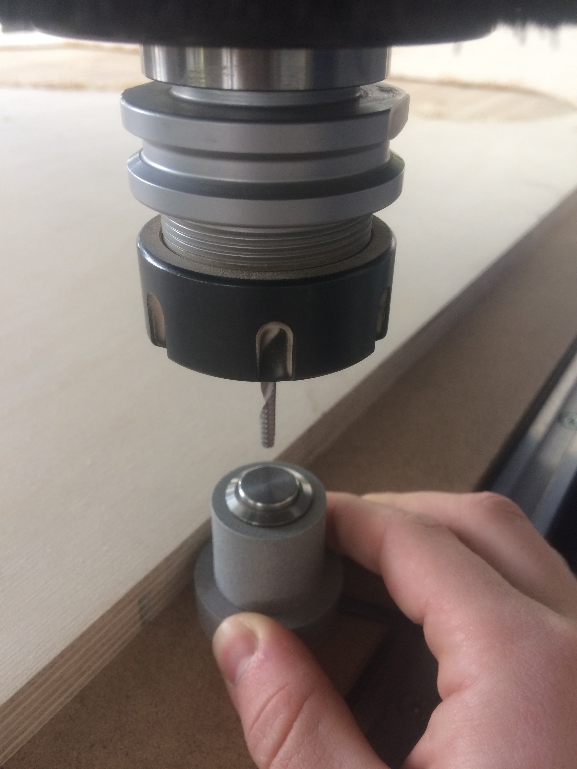
Important thing is to place it on the bed of the machine!
Now I can launch the first job, which is making the engraving. These are the settings which I used:

I press Calculate Toolpath to simulate the job and make sure that there are no collisions! After I save the .GCode, and launch the job, I get this window:

Now I can launch the outside cut:


This is what I get after the job is done:

Another piece which I had to mill is used for the Moulding & Casting section!
I prepared the mould to waterproof my water container. Here is the design:

There is nothing new about this. I used exactly the same settings as above. The only thing is the material thickness was 10mm wood, and I had to cut 7 pieces, to glue them together later and prepare my mould!
Download Files:
Moulding & Casting
I used this technique in order to prepare a water container, to waterproof my existing container! I see it as a thin layer of material (a smaller container) which can be easily removable!
This is the result from the previous section CNC Milling

I cut 7 identical pieces, and aligned them using the reference holes! I also cut a big hole in the middle of 5 bottom pieces, in order to place the air pump inside, and easily remove the cast later.
After I glued all the pieces together, and fixed them, this is how it looks:

While waiting for the glue to dry out, I prepared a little plastic "thing" (do not know how to call it :D) for the pump. The idea is to be able to screw it on my mould, and remove it whenever I want!
When the mould is ready, this is how it looks:

And the back side:

I am ready to vacuum cast!
I used a vacuum machine available in our FabLab Kamp-Lintfort called Formech – Manual Vacuum Forming Machine
The thing is that I tried to do it many times, and all the time I could not remove the mould without breaking the cast! After several hours of trials, I came up with a solution! First, I vacuum casted one thin layer of material, and without removing it, I will cast the actual container on top of it. The first thin layer is slippery, and If I spray it with silicon, it will allow me to remove the mould way easier
After I let the silicon to dry a bit, I can cast the actual layer!
And here we are!!!
A hero shot for those who may thing that it was easy


Putting All Together
Now, let's put everything together! I will start by assembling the structure. Put next to me all the necessary tools:

A short animation of the process:

To assemble the lights, I cut the RGB LED stripes into 4 pieces (I measured the length in advance), and soldered them accordingly!

After I connected all the sensors, and managed the wiring, I fixed the board in the electronics section

And here it is the system!!! Everything assembled, nice looking growing system GIY

A HERO shot during the working process!

Final Presentation Video