Final Project
2D and 3D Design
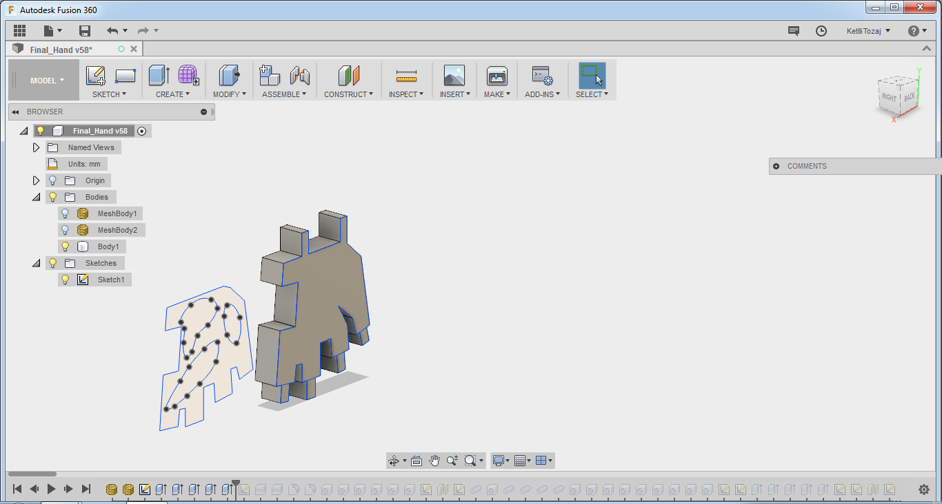
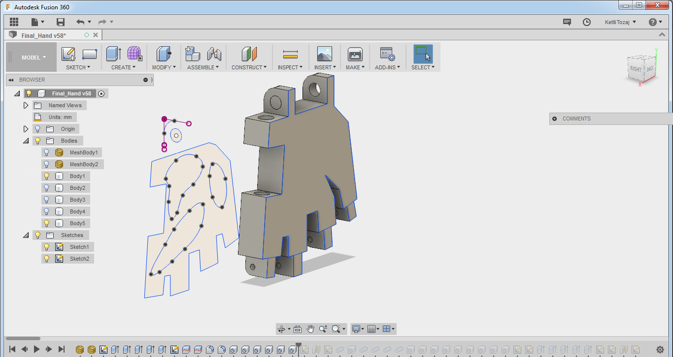
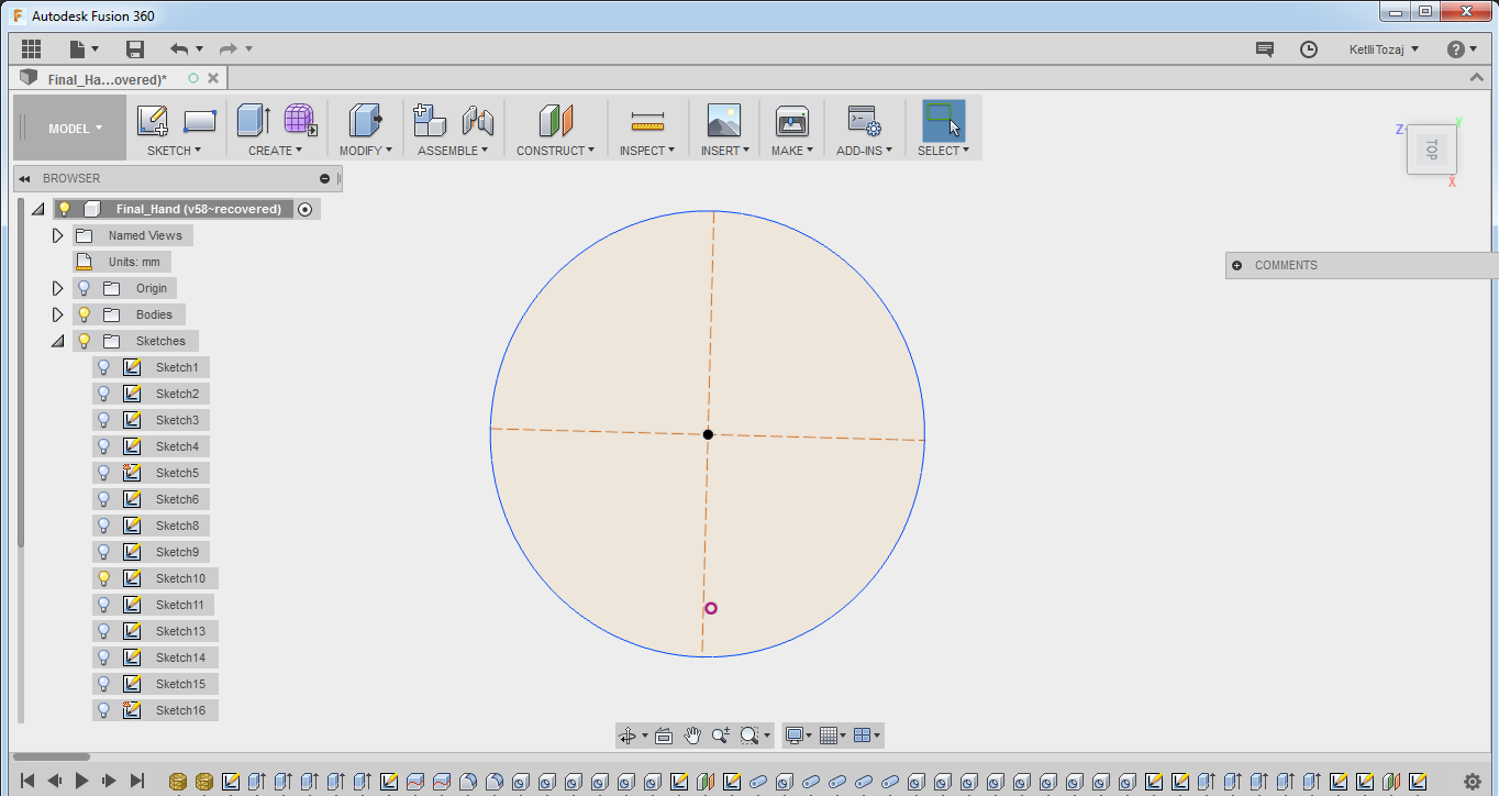
It all started with the design of the structure of my final project. The most difficult part for me was to figure out the dimensions of the fingers between them and of each part of the finger seperately. To be honest, I made some research but it was difficult for me to imagine how to design them. So, for the fingers, I downloaded the .stl files from an open source project Inmoov. After the fingers were ready I had to design the rest of the hand accordingly. So, taking into consideration the dimensions of the fingers, the relative distance that they should have from each other and the connections between them and the palm, I started with a simple sketch, and extruded the palm to a different height of the extrution of the connections between the fingers and the palm so that they have a degree of freedom when they move. Also, by creating another sketch, I created a hole and a fillet to the connection part of the hand with the forearm and I used the fillet function and hole for the connection between the fingers and the palm.
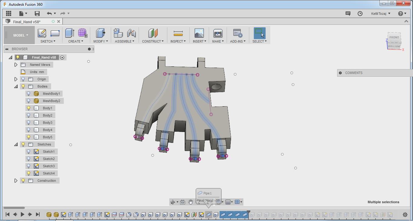
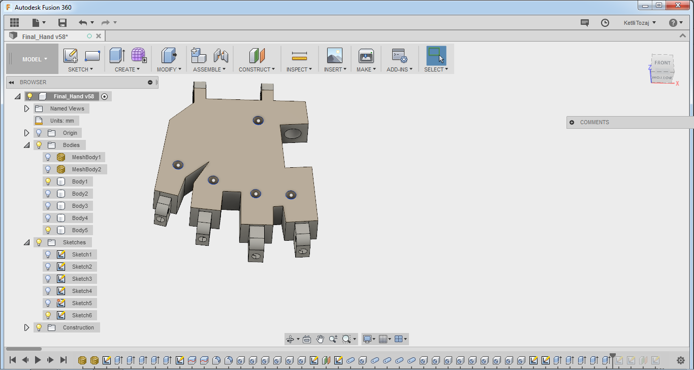
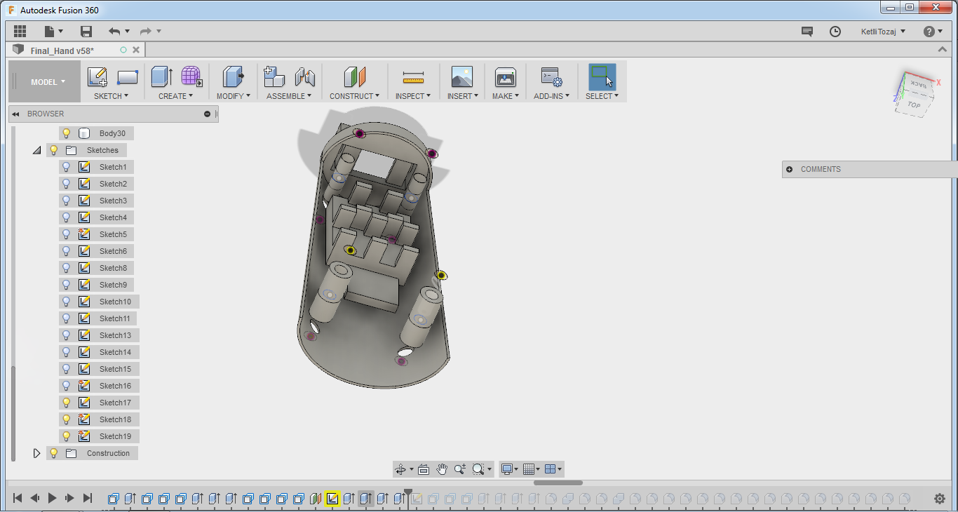
After that, I had to think of the connections between the fingers and the forearm where I was planning to put the servo motors, so that the fingers move. For this, I had to create pipes inside the palm. For that, I constructed an offset plane in the middle of the palm, made a sketch and then used the pipe function to create pipes in the palm. I also used the hole function in the end of the pipes because it was not penetrating all the way through the design.
I firstly printed the palm with the descriptions above, but after doing some testing I noticed that the fingers were not closing with that configuration. So, I created holes in the inside of the palm so one of the two finishing line wires to pass through that. After testing with this configuration, the fingers were able to open and close.
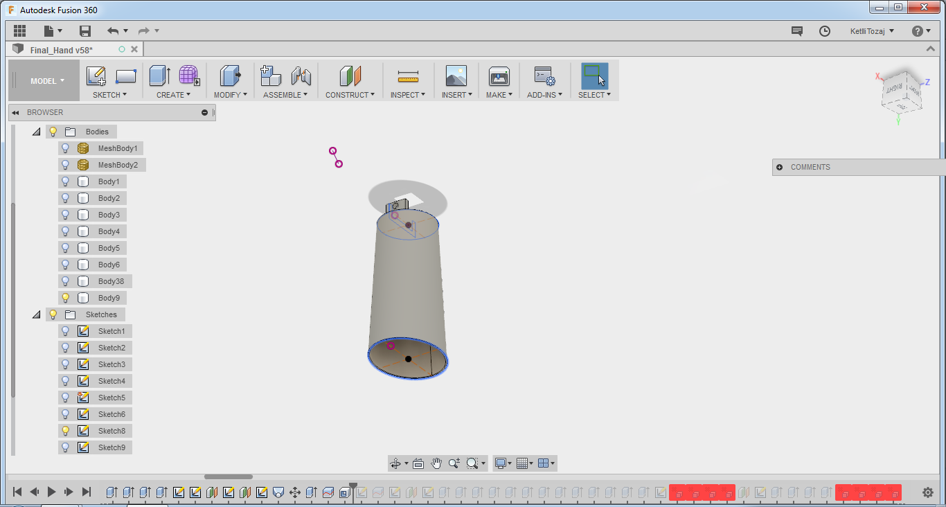
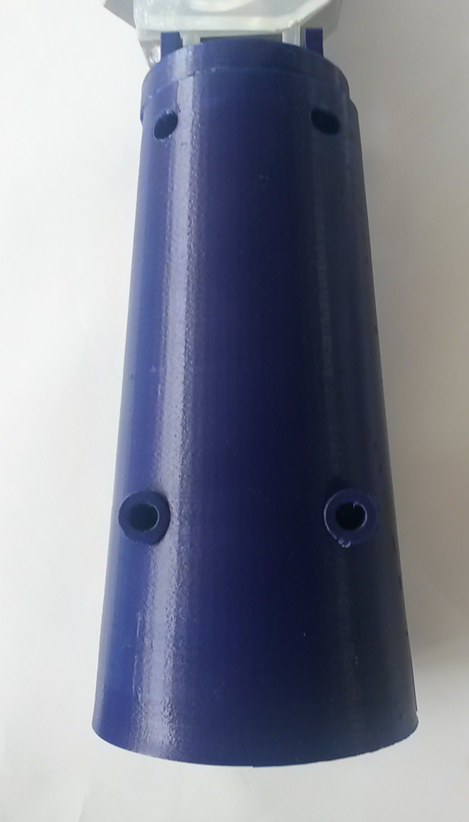
After the hand was functioning properly, I proceeded to make the design of the forearm. Again, having the dimensions of the connection part of the palm in mind, I created firstly a sketch for the connection between the palm and the forearm and then I created two offset planes, one "touching" the end of the sketch that the connection between the hand and the forearm was and the other one with some distance from the first one. In both I used the ellipse function with the second ellipse being slightly bigger. Then, I used the loft function and the shell so that I have a kind of cylinder that is hollow. At the first try, the cylinder was too small and as a result I could not close it and the motors did not have enough space to move freely. So, I printed another one with the cylinders being of a bigger diameter.
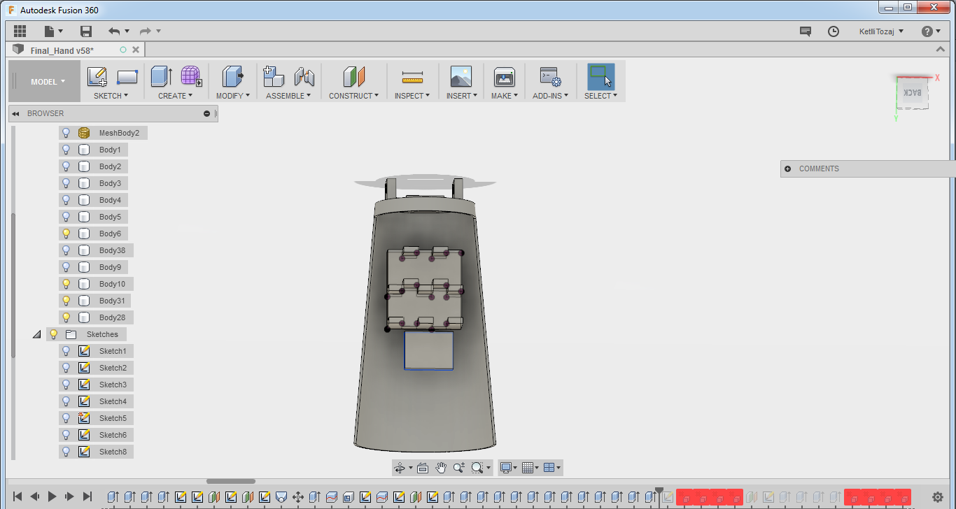
Proceeding to my design, I cut the cylinder in half and continued to make slots for the pcb and the servo motors as the surface being round, I could not attach them properly to it. So, I created a design according to the dimensions of the servos. I extruded the sketch towards the forearm and then as the surface of it exceeded the surface of the cylinder letting flat surfaces on it, I had to delete it. To do that it was very easy but it took quite a while to figure out. All I had to do was to click on the surface I did not need and click backspace and just like magic the surface disappears.
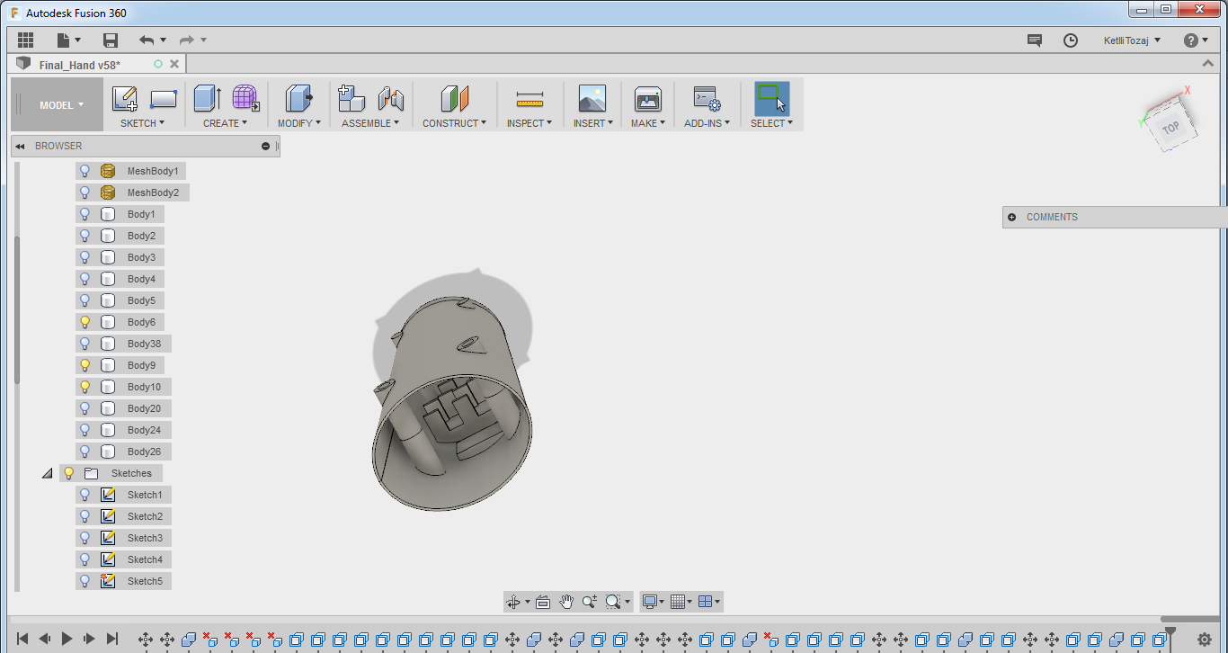
Lastly, I had to close the arm somehow, so I had to create slots for the bolts that I used from the fab lab. To do this I created a sketch consisting of two circles. One circle was designed to be 2mm bigger than the upper part of the bolt and the other circle was designed to be the exact same size of the down part of the bolt. Then, I extruded the bigger circle until it touches the cylinder and the other part until the half of the distance of the bolt. I repeated the same procedure for the upper part of the forearm, so the distance of the insertion of the bolt was perfect. After this, the forearm design was ready!
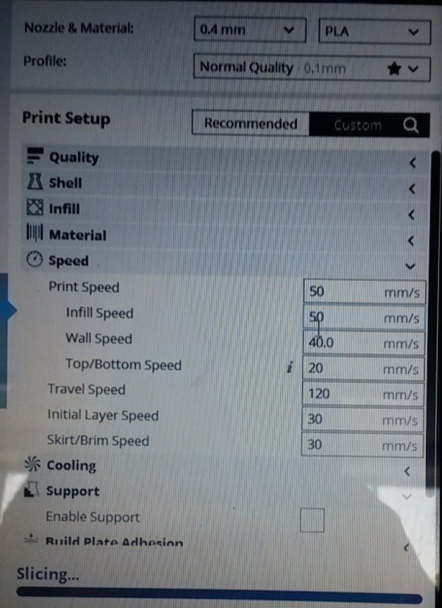
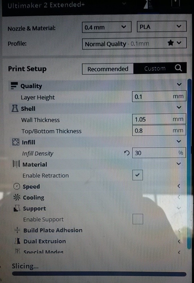
The settings to which every part was printed were:
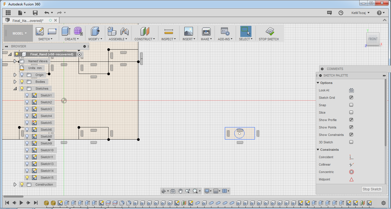
For the 2D design, I did not have to make anything new but rather use the sketches I already had created in advance. So, I printed out the smaller ellpise I designed for the loft as I wanted the wires to be separated smoothly from each other. So, I laser cut the ellipse and then I drilled small holes of a diameter of 0.8mm after I marked the area I had to drill the holes to. Also, after testing the movement of the motors with this assembly, I figured that the round insertions were collapsing with each other. So, I used a part of the sketch for when I designed the slots of the motors and then also designed a small hole in the middle so that the bolt would fit.
Molding and Casting
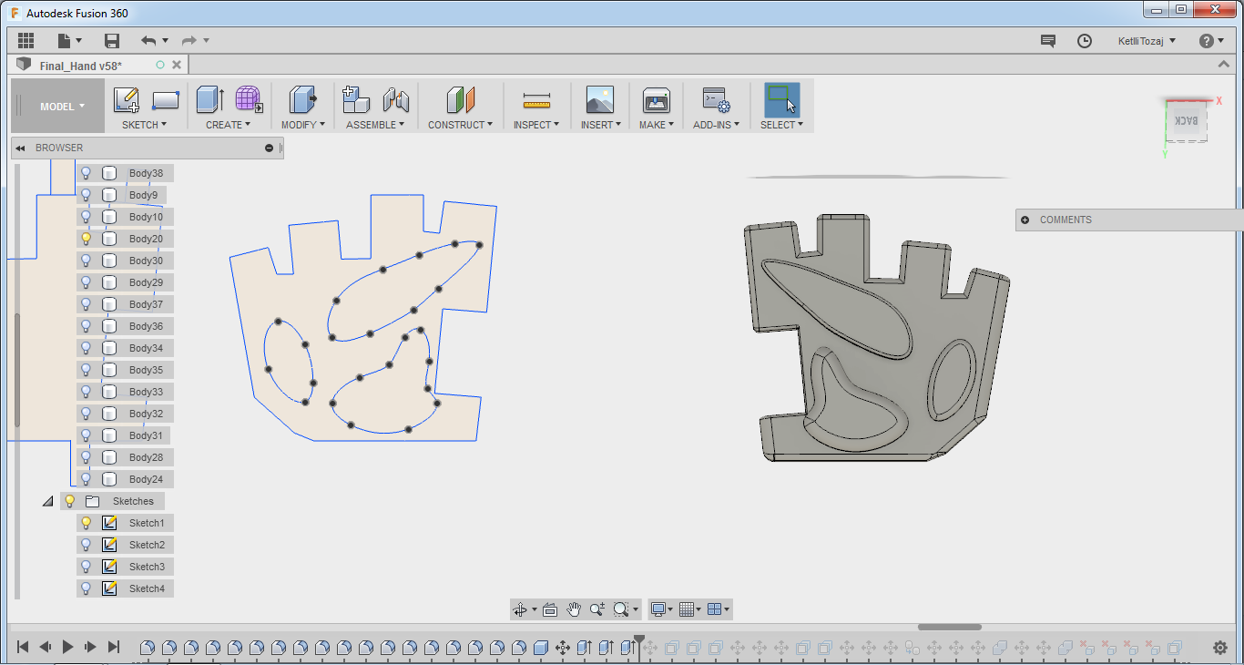
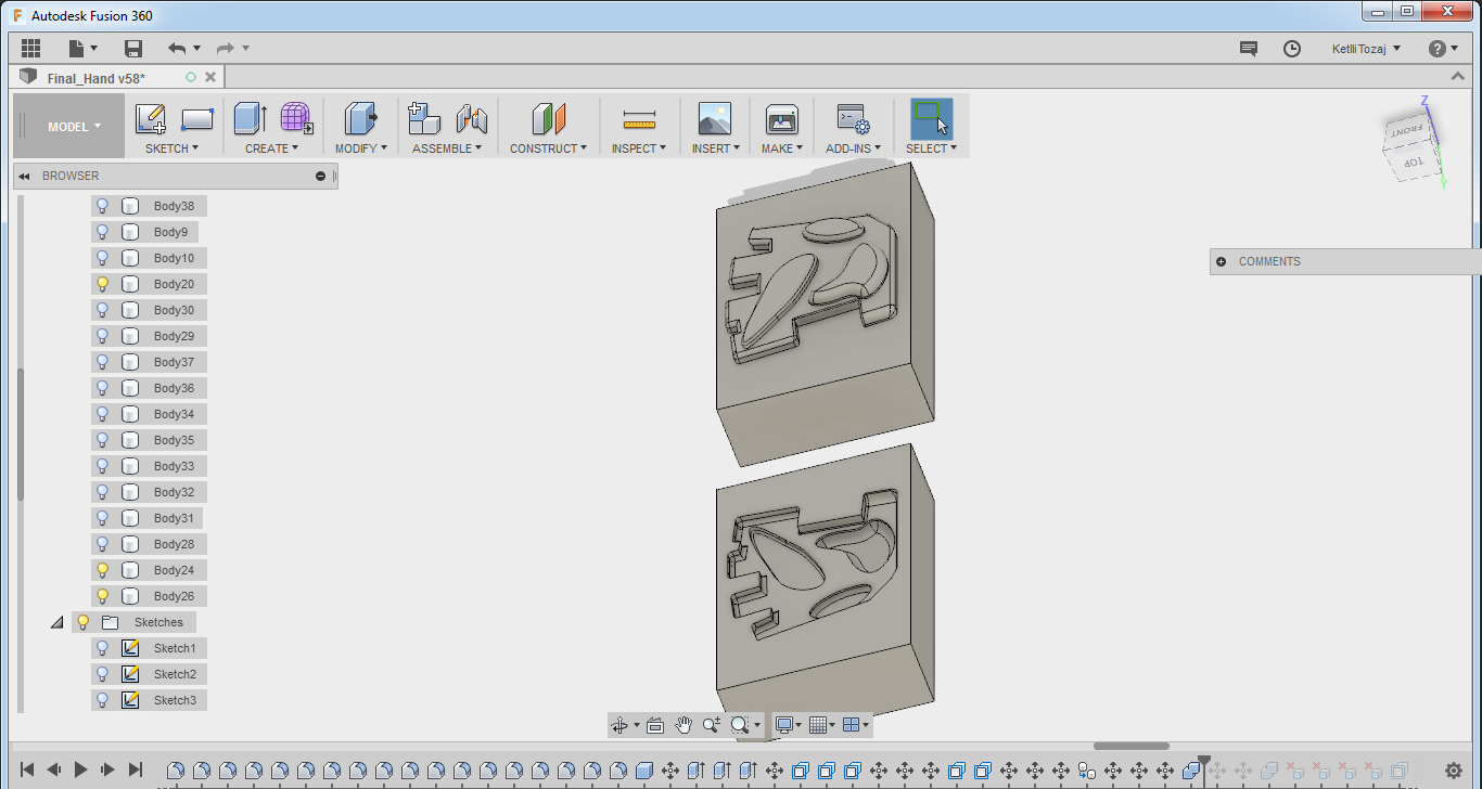
Molding and casting was used to make the palm area stronger. What I used for casting was only the silicon. So, first of I had to made the mold. For that I used Fusion and then I engraved it using the Roland machine 40A that we have in the lab. After I made the design then I extruded the parts on different heights and made fillets in the end of every part of my design. After that, I placed the design on a box of dimensions the same with the wax block we had in the lab, copy pasted the piece, flipped the palm and made a cut.
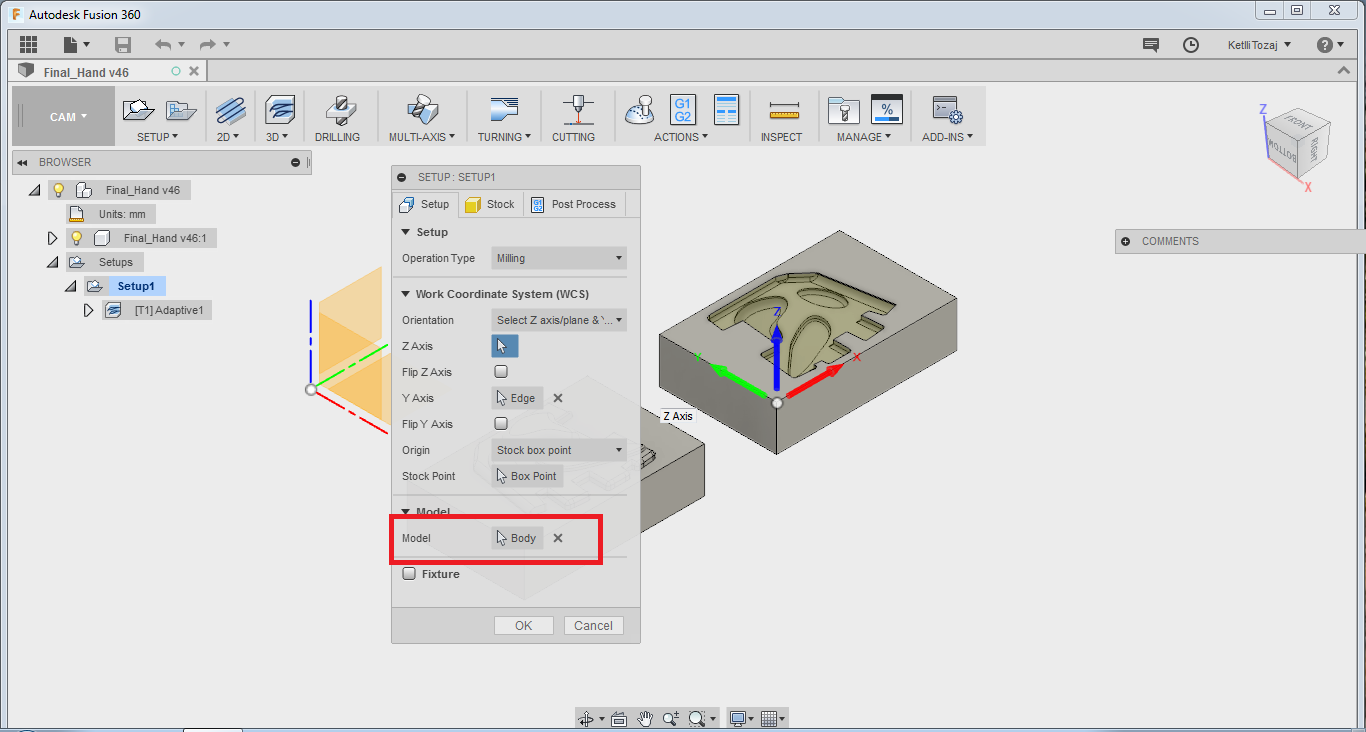
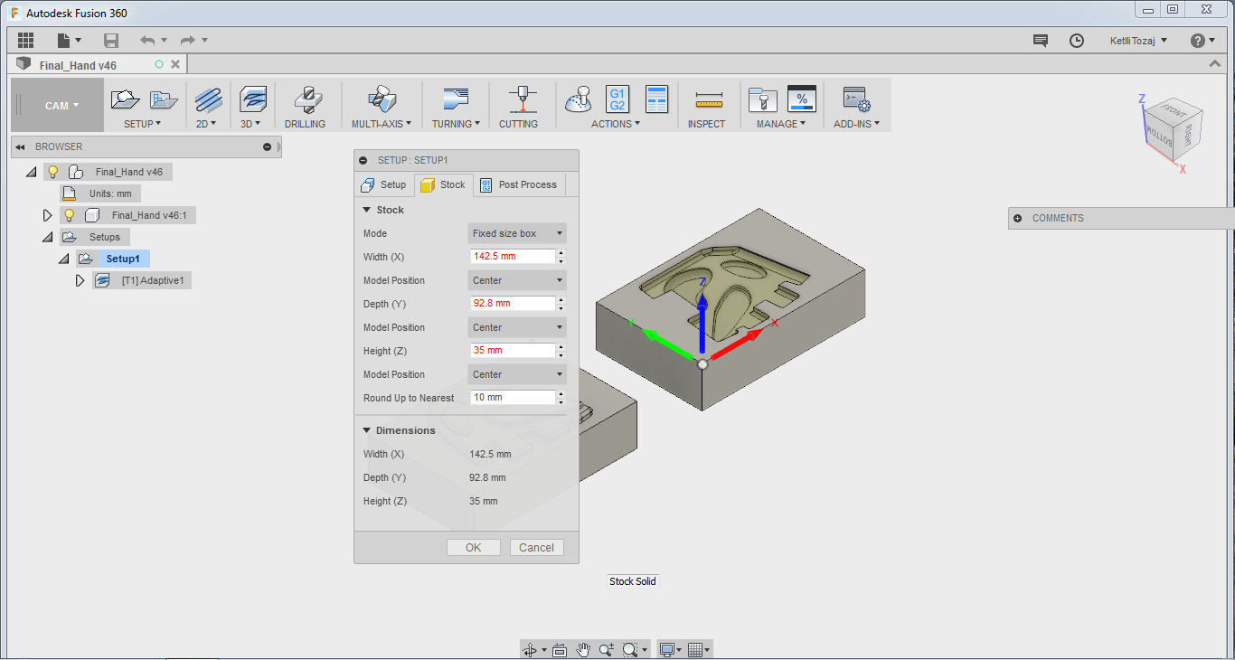
After the design was done, I proceeded to the CAM process of fusion. I made a new setup and a window popped up. On that window on the setup, I made sure to choose the body I wanted to mill as I had more than one bodies on my design. On the stock setup I set the size of the block of wax I had available. Below you can see the settings I set for the setup.
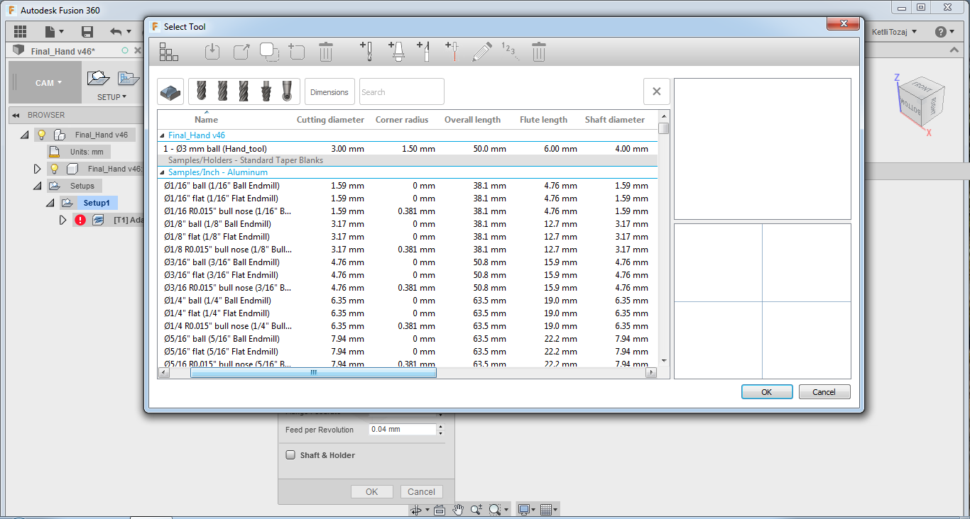
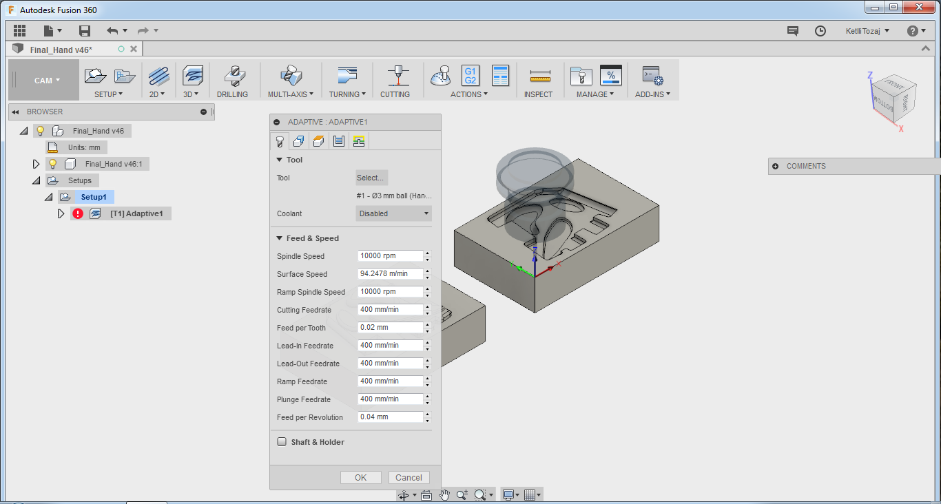
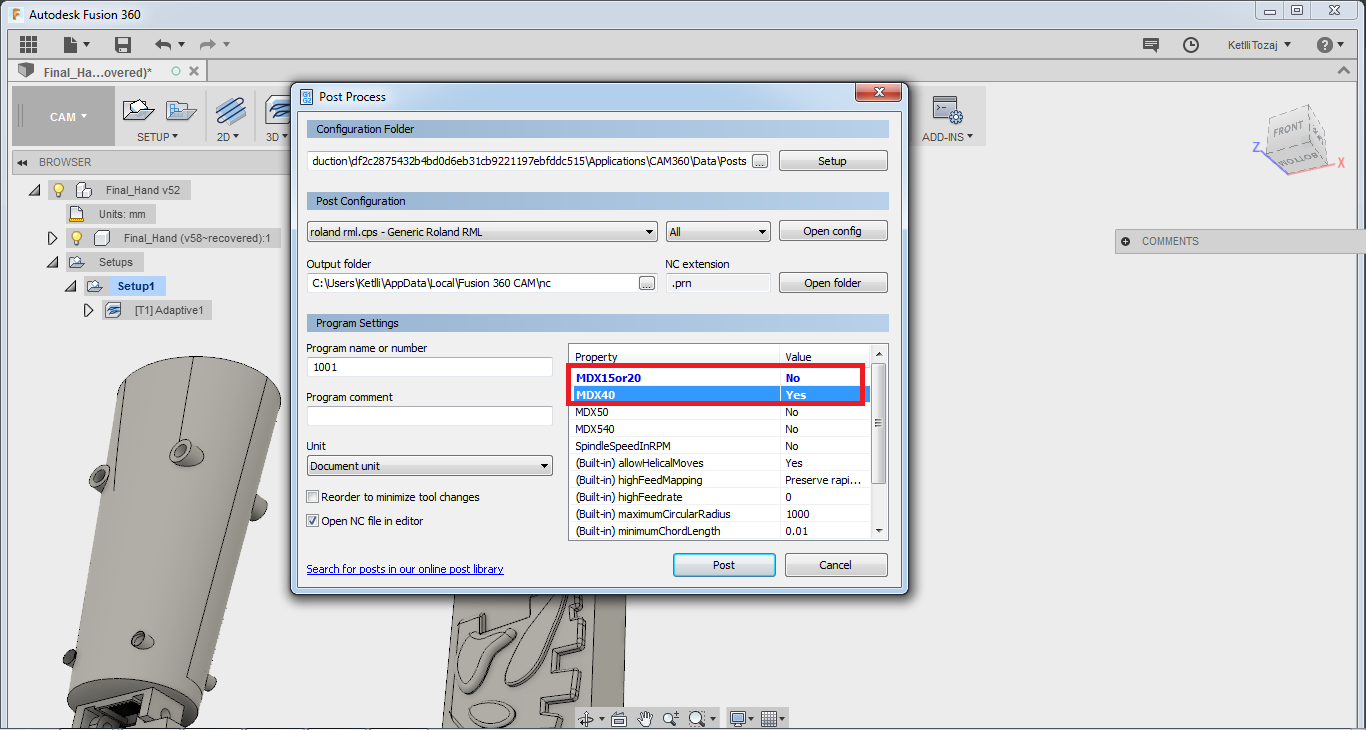
Then I proceeded to make an adaptive clearing under the 3D menu. After choosing the tool that I wanted to mill with, I inserted it in fusion and then chose it for my milling process. More details on how to insert a tool in the library, you can go to the Molding and Casting week. Below, you can see the specifications of the tool used and the setup of it as the speed rate etc. Also, you can see the specifications of the passes and the post process. I made sure on the post process to choose the correct milling machine.

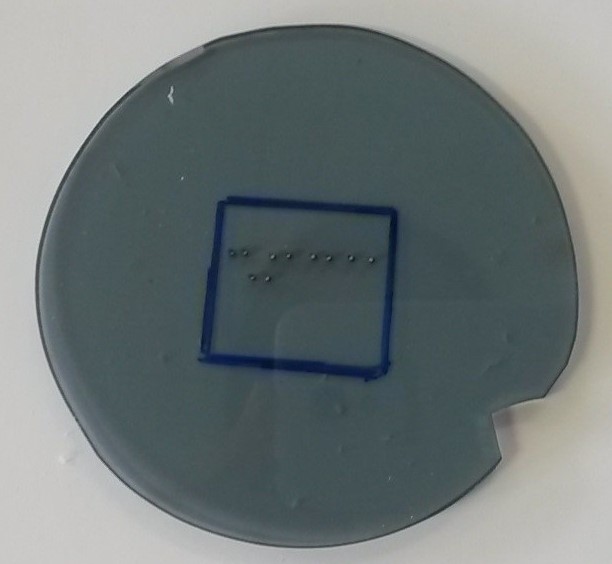
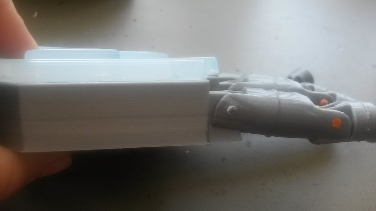
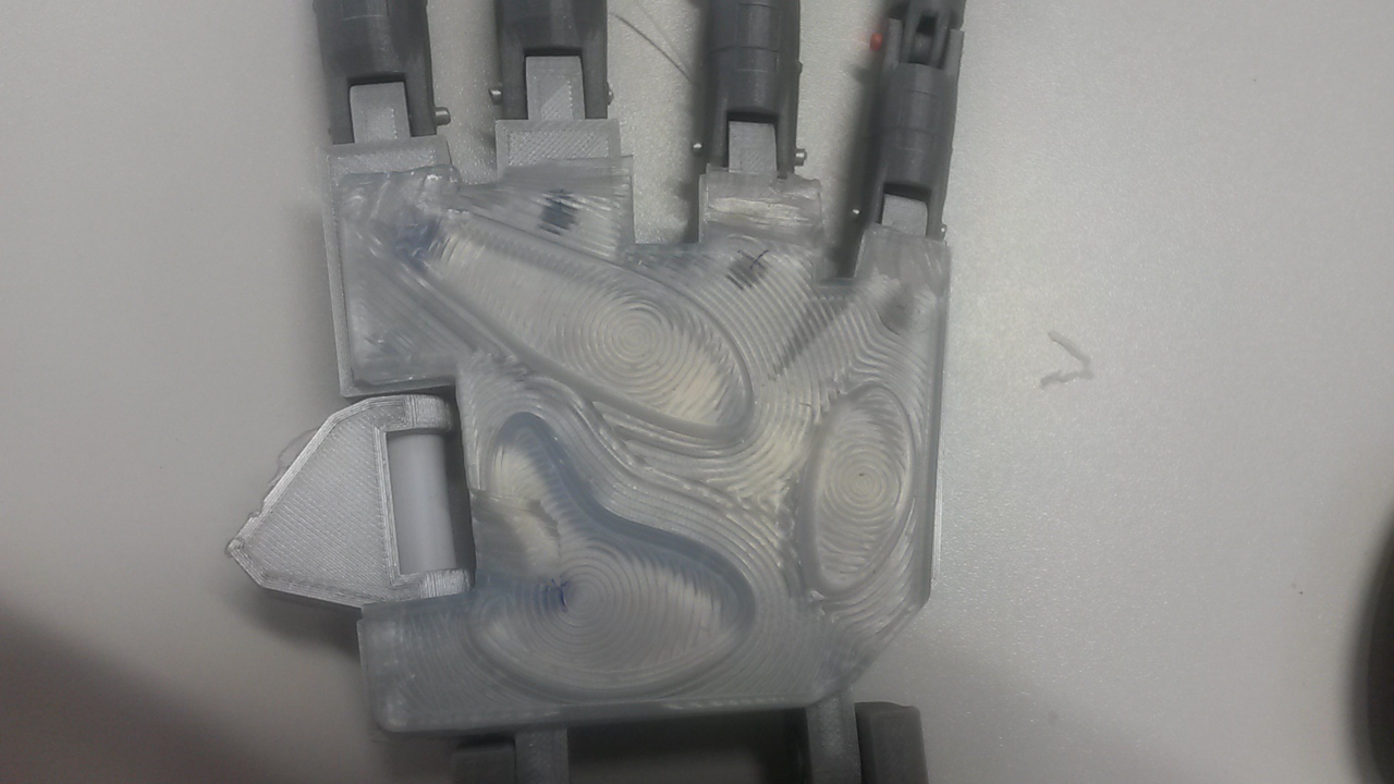
After the mold was ready, I did cast the resin like it was indicated in the Molding & Casting week. So, after a day the silicon was ready to use. But, as you can see the silicon was too high and I was concerned for the fishing lines so I took the cutter and made fillets in hte endings. Also, one thing I did not consider while making the design were the holes for the fishing lines. So, I became creative and made my own holes using hole pliers.
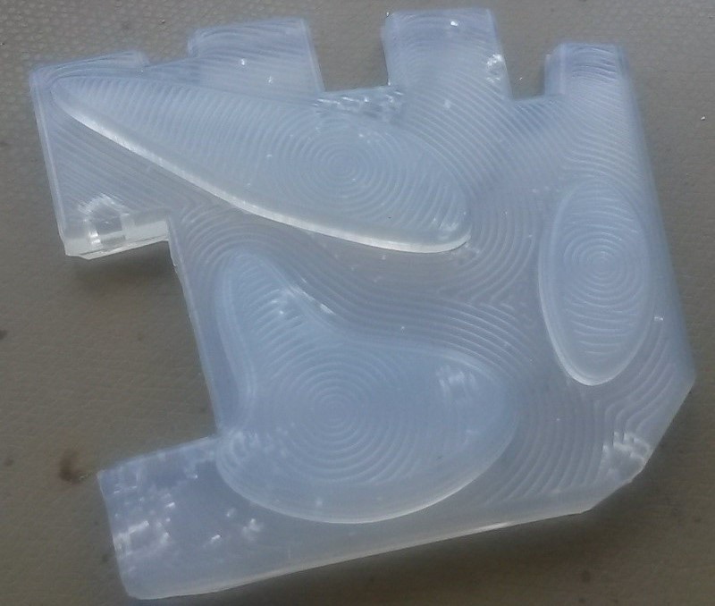
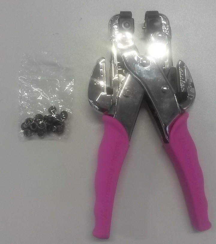
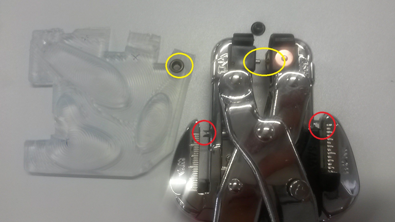
In the picture below you can see the holes done in the silicon. The red circles indicate the areas of the pliers that were used to make the holes whereas the yellow ones were used to put the little circles in the hole for more stability. I must say not every little circle fit to the hole because of the curve. Also, the direction we put the circle does not really matter.
Electronics Design and Production
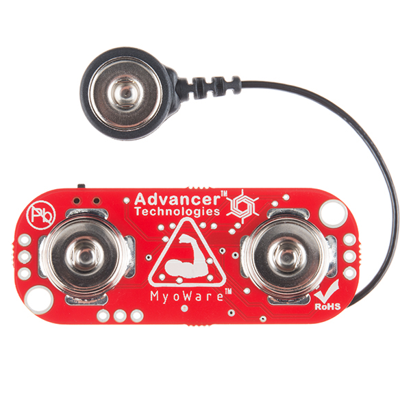
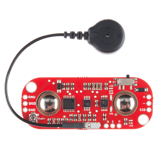
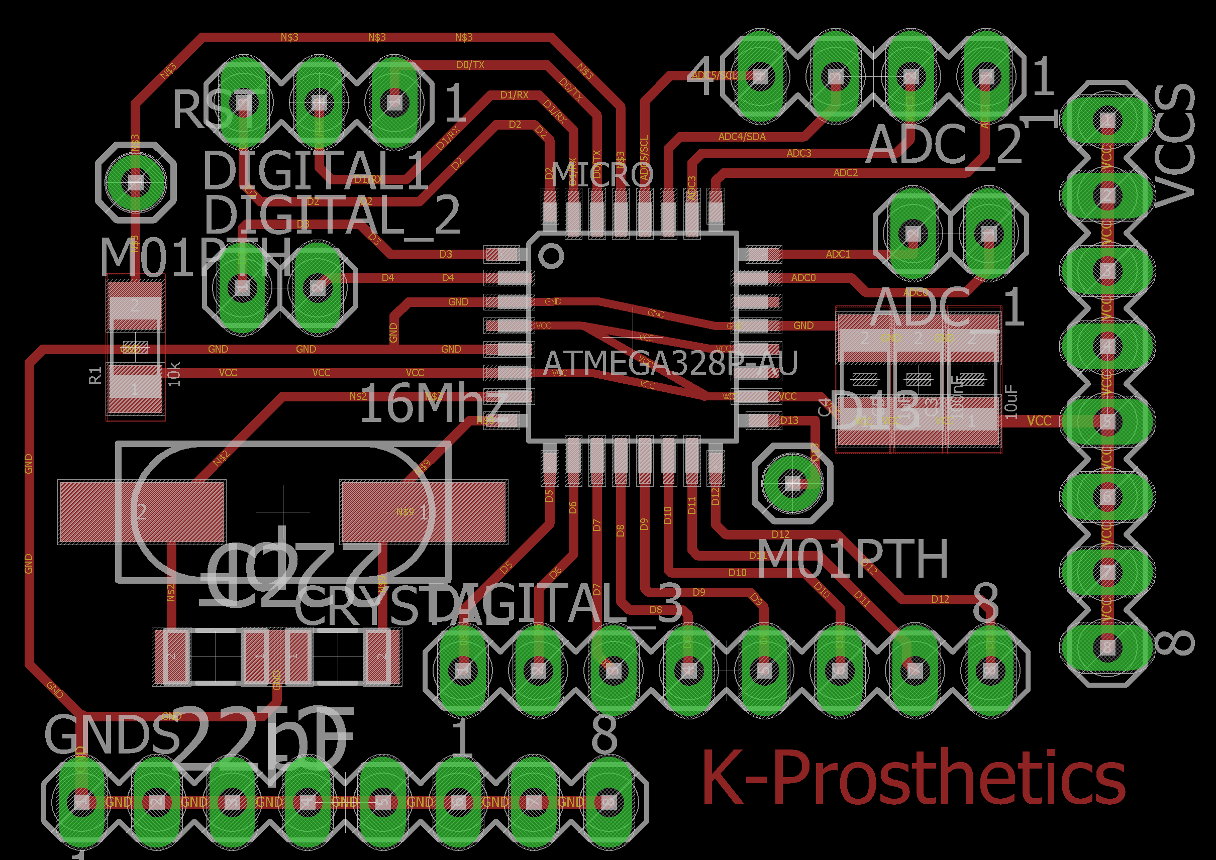
So, for the electronics part I had to take into consideration the things I wanted to connect. I wanted to connect five servo motors and one myosensor. For the pcb design I used the micro satshakit as a base design and added more GNDs and VCCs to it and I re-routed it again. I did not have to consider the battery supply as I bought a power bank with an on/off button that was giving a 5V ouput, which was meeting my power requirements.
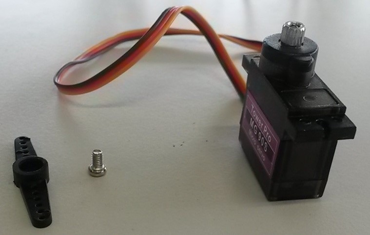
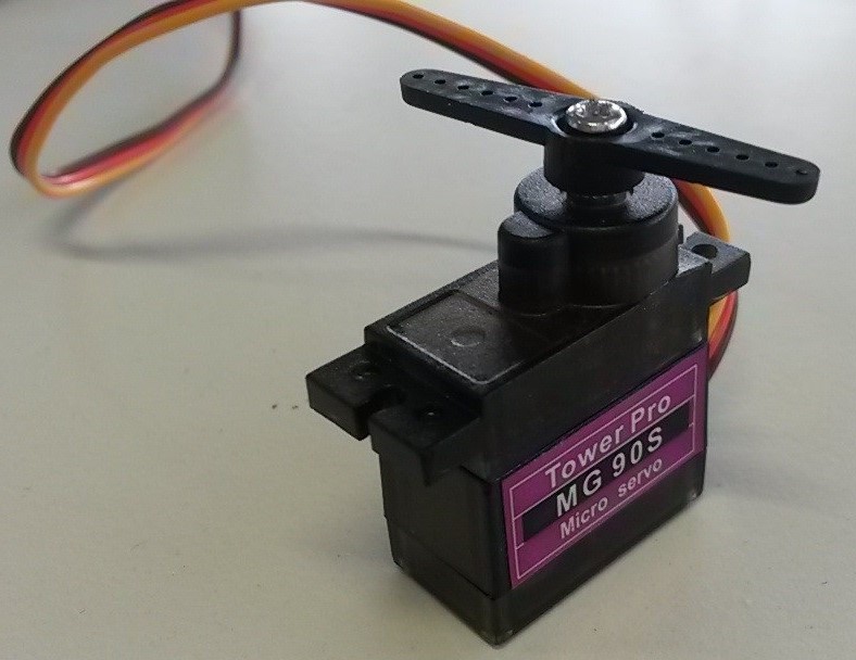
One servo motor, in order to be connected, it needs a PWM pin, a VCC and a GND. For more detailed description, you can go to the Output Devices week. So, I needed five PWM pins, five GNDs and five VCCs. For the myosensor, I needed an analog pin, a GND and a VCC. For a more detailed description, you can go to the Input Devices week.
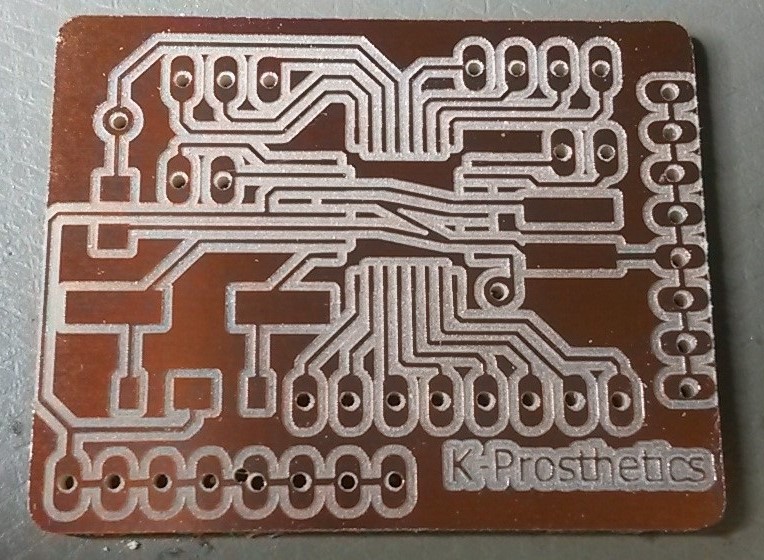
After, I took everything into consideration I went for milling. I exported the image from eagle and derived the external and internal path of it. The configurations used for the internal path were:
Respectively, the settings I used for the external path, were:
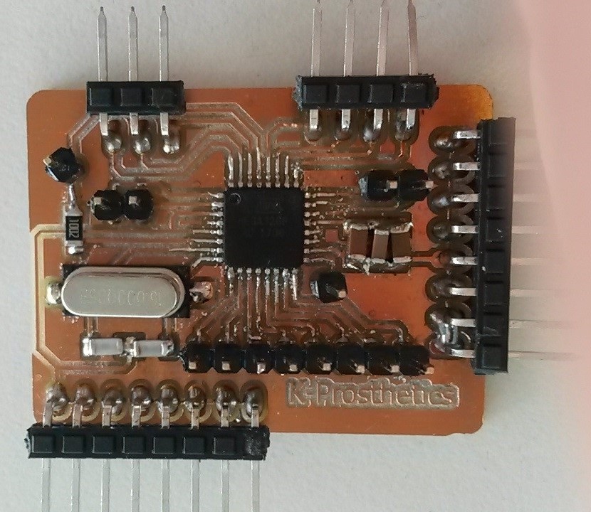
Below, you can see the pcb:
Assembly
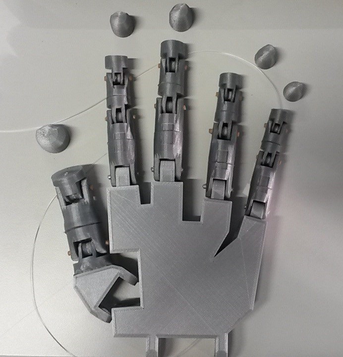
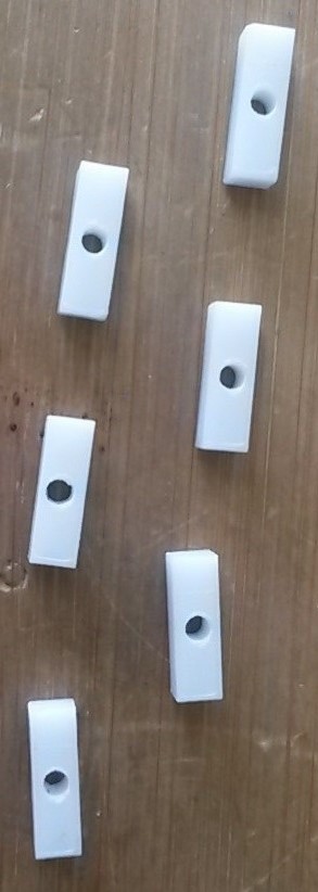
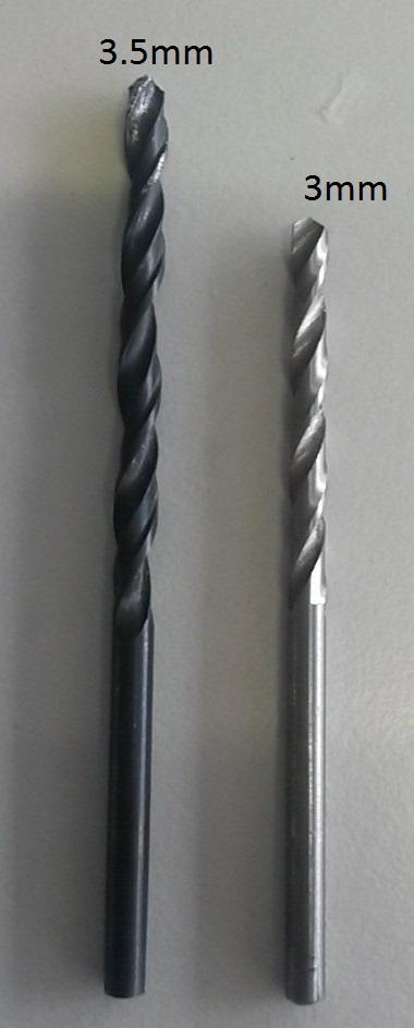
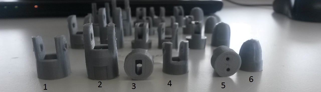
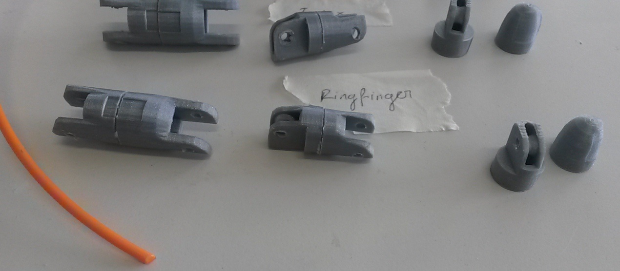
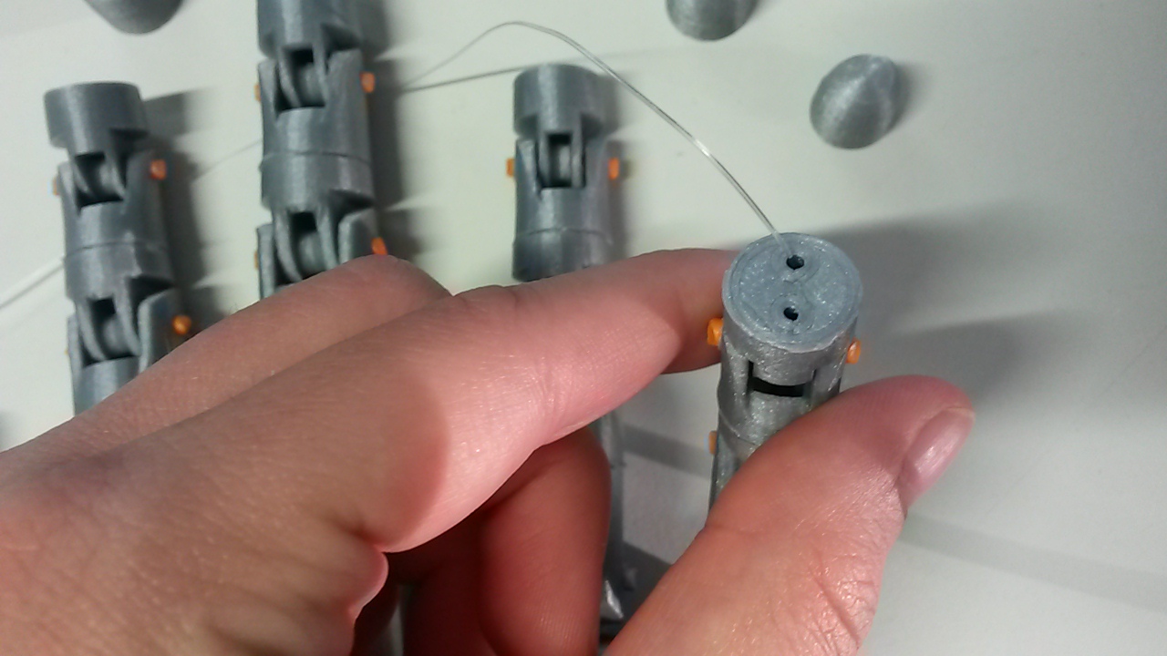
So, after the fingers were printed, I had to drill the inside holes with a 3.5mm diameter drill and the outside holes with a 3mm diameter drill. After that I had to superglue to first with the second finger and the third with the fourth one. After that, I connected parts 1+2 with 3+4 with 5 through the little holes using a filament with a 3mm diameter. After that, the fingers were ready to be assembled with the palm and then with the forearm.
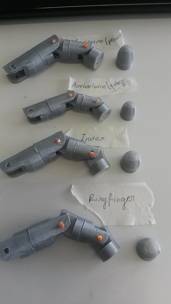
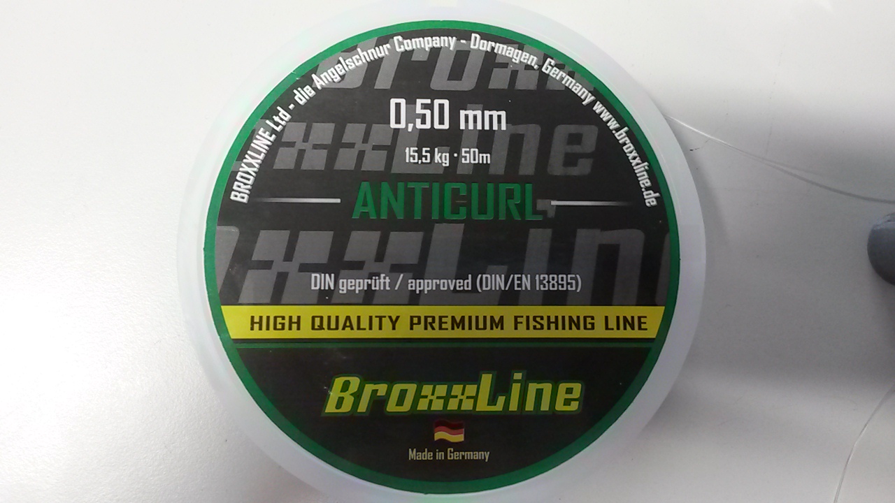
So, it was time to pass the fishing line through the fingers. One line went from the back side of the finger through the pipe on the finger-palm connector and to the forearm and the other line went from the front side of the finger to the hole on the inside of the palm and to the forearm. A special note is to pass the fishing line through a piece of wood that has a hole to it with the diameter of it and make a knot. Otherwise when the line is pulled, it may go down the finger, which happened to me no matter how many knots I made.
After the fishing line was passed and the fingers, the palm and the forearm connected by some bolts that were 3D printed, I passed the lines again through the laser cut hole slot to separate them and then connected them to the servo motors. Finding the position of the line to attach to the servo ws a bit challenging. But, what I did was to take the extreme positions of the finger and connect it to the extreme position of the servo. After I found the correct positions, I drilled holes into the special slots for the servos and screwed the servos to the right places.
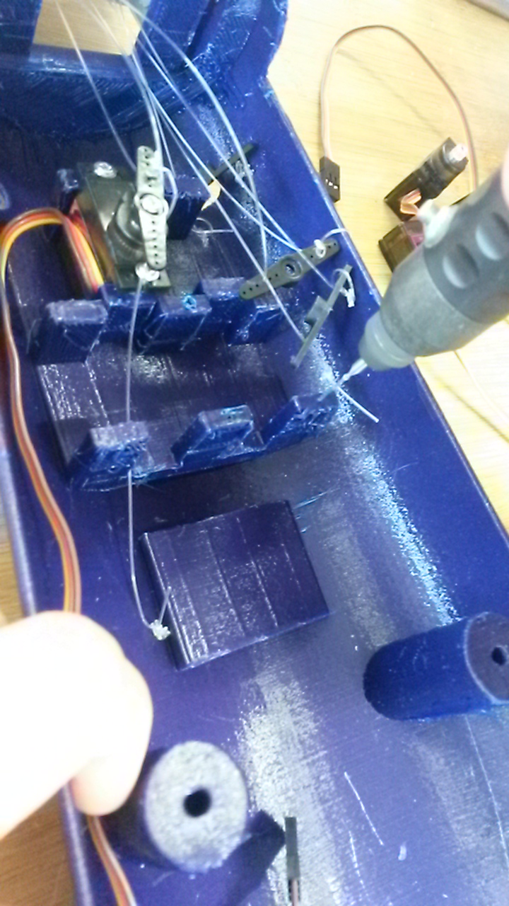
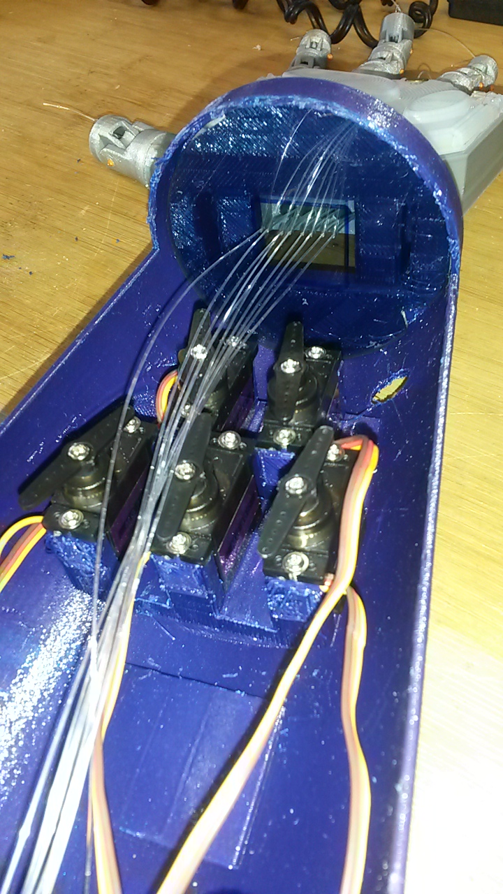
A problem occured while operating it though. When all the servos were operating simultaneously, there was no room for it to spin normally, so I elevated two of them. So, I put some thick double scotch tape from below and the laser cut supports on the slots for the servos' bolts.
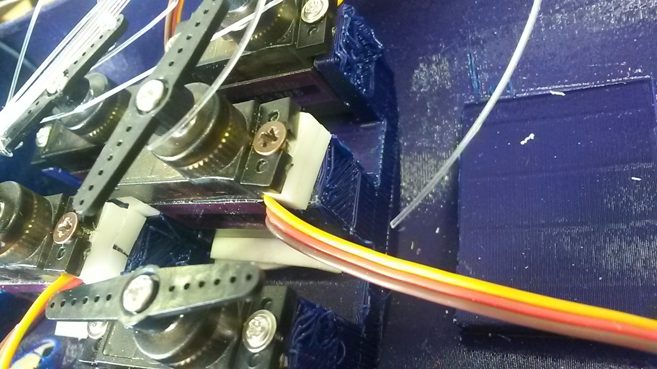
Below, you can see the first testing by hand:
Embedded Programming
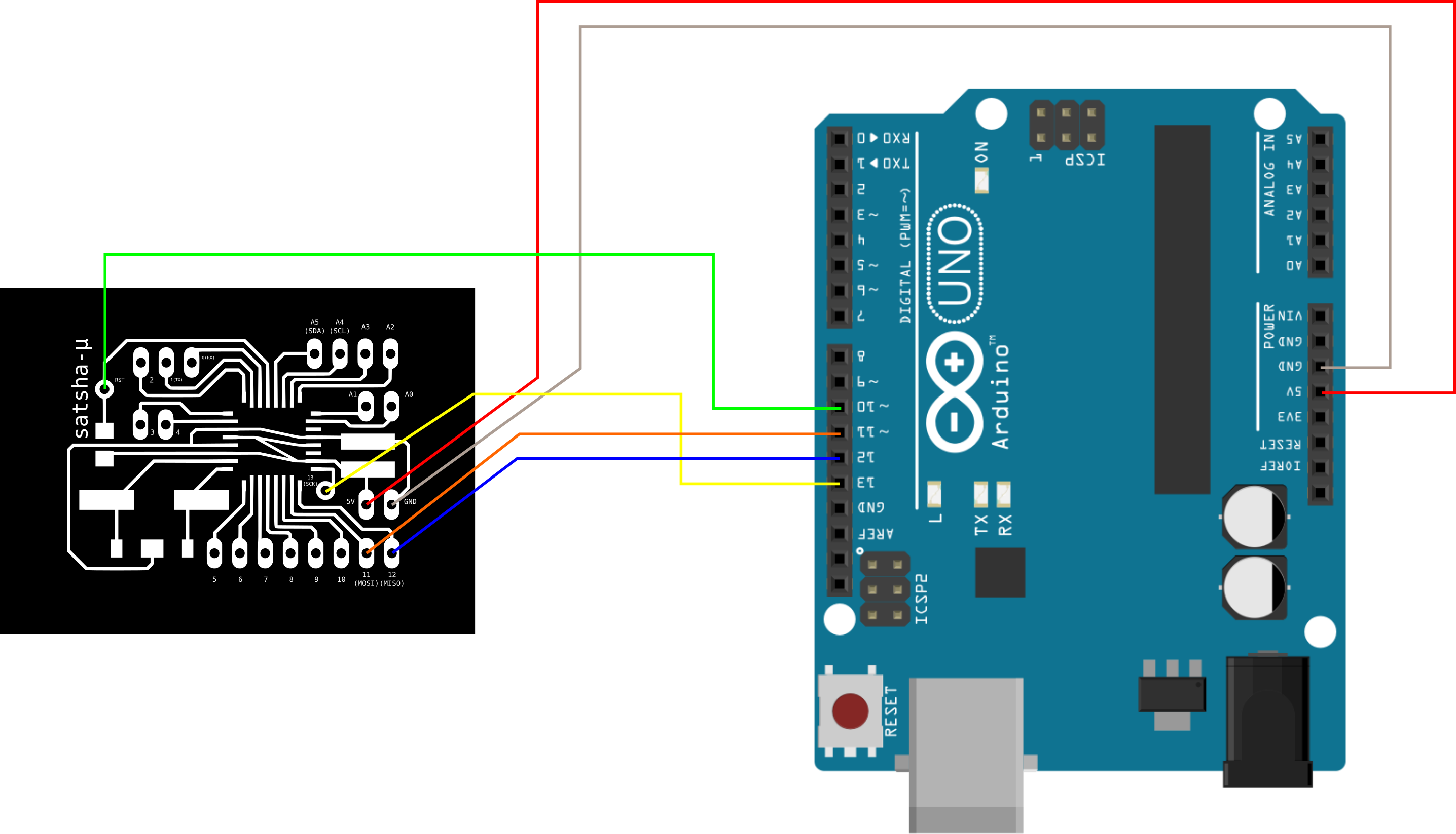
So, as I mentioned, I used the micro satshakit. I programmed satshakit via the Arduino board. So, firstly I made sure I uploaded the Arduino as ISP to it before I connected the satshakit to it. After that, I connected the Arduino to the satshakit following the schematic below and I burned the bootloader to it. For more detailes on how to do that, you should go to the Output Devices week.
After everything was set and the bootloader was successful, I started programming the board. Firstly, I programmed it without the myosensor so that I can see the movement and then I embedded the myosensor as well. The Arduino code is:
                            // including the library that I used for the servo motors
#include <VarSpeedServo.h>
#include <SoftwareSerial.h>

SoftwareSerial mySerial(7, 8);

//defining myosensor pin and values
#define MYO_PIN A0
int sensorValue;
float voltage;

//defining my servos
VarSpeedServo servo1;
VarSpeedServo servo2;
VarSpeedServo servo3;
VarSpeedServo servo4;
VarSpeedServo servo5;

//defining the pins each servo is attached to each finger
#define PINKY 5
#define PINKY_PIN 10

#define RINGFINGER 4
#define RINGFINGER_PIN 9

#define MIDDLE 3
#define MIDDLE_PIN 3

#define INDEX 2
#define INDEX_PIN 5

#define THUMB 1
#define THUMB_PIN 6

void setup() {

  //set myosensor as an input
  pinMode(MYO_PIN, INPUT);

  // the pin which I attached my motor
  servo1.attach(THUMB_PIN);
  servo2.attach(INDEX_PIN);
  servo3.attach(MIDDLE_PIN);
  servo4.attach(RINGFINGER_PIN);
  servo5.attach(PINKY_PIN);

  //set the initial position of the motors
  defaultPosition(THUMB, 40);
  defaultPosition(INDEX, 40);
  defaultPosition(MIDDLE, 40);
  defaultPosition(RINGFINGER, 40);
  defaultPosition(PINKY, 40);

  mySerial.begin(9600);
  mySerial.print("Initializing...");
}

void loop() {
  /* degrees of my servo turning, the speed and true if
  it is going to wait for the last movement to happen */
  /*servo1.write(0, 40, true);
  servo1.write(20, 40, true);
  delay(500);/*/

  //reading sensor value
  sensorValue = analogRead(A0);
  voltage = sensorValue * (5.0 / 1023.0);
  mySerial.println(voltage);
  delay(100);

  //if the reading is more than 1, close the fingers
  if (voltage > 1){
  closePosition(PINKY, 60);
  closePosition(RINGFINGER, 60);
  closePosition(MIDDLE, 60);
  closePosition(INDEX, 60);
  closePosition(THUMB, 60);
    }
  //else open the fingers
  else{
  openPosition(PINKY, 60);
  openPosition(RINGFINGER, 60);
  openPosition(MIDDLE, 60);
  openPosition(THUMB, 60);
  openPosition(INDEX, 60);
    }


  //the commented section below works without the readings of the myosensor
  /*closePosition(PINKY, 60);
  closePosition(RINGFINGER, 60);
  closePosition(MIDDLE, 60);
  closePosition(INDEX, 60);
  closePosition(THUMB, 60);

  delay(500);

  openPosition(PINKY, 60);
  openPosition(RINGFINGER, 60);
  openPosition(MIDDLE, 60);
  openPosition(THUMB, 60);
  openPosition(INDEX, 60);

  delay(1000);

  peacePosition(60);

  delay(500);

  rockPosition(60);

  delay(500);*/
}

void defaultPosition(uint8_t finger, uint8_t _speed){

  if (finger == PINKY)
    servo5.write(90, _speed, true);
  else
  if (finger == RINGFINGER)
    servo4.write(70, _speed, true);
  else
    if (finger == MIDDLE)
    servo3.write(20, _speed, true);
  else
    if (finger == INDEX)
    servo2.write(20, _speed, true);
  else
    if (finger == THUMB)
    servo1.write(20, _speed, true);

  }

//this function closes the fingers
void closePosition(uint8_t finger, uint8_t _speed){

  if (finger == PINKY)
    servo5.write(180, _speed, true);
  else
  if (finger == RINGFINGER)
    servo4.write(180, _speed, true);
  else
    if (finger == MIDDLE)
    servo3.write(180, _speed, true);
  else
    if (finger == INDEX)
    servo2.write(180, _speed, true);
  else
    if (finger == THUMB)
    servo1.write(180, _speed, true);

  }

//this function opens the fingers
void openPosition(uint8_t finger, uint8_t _speed){

  if (finger == PINKY)
    servo5.write(0, _speed, true);
  else
  if (finger == RINGFINGER)
    servo4.write(0, _speed, true);
  else
    if (finger == MIDDLE)
    servo3.write(0, _speed, true);
  else
    if (finger == INDEX)
    servo2.write(0, _speed, true);
  else
    if (finger == THUMB)
    servo1.write(0, _speed, true);

  }

//this function closes the fingers mid-way
void middlePosition(uint8_t finger, uint8_t _speed){

  if (finger == PINKY)
    servo5.write(135, _speed, true);
  else
  if (finger == RINGFINGER)
    servo4.write(125, _speed, true);
  else
    if (finger == MIDDLE)
    servo3.write(100, _speed, true);
  else
    if (finger == INDEX)
    servo2.write(100, _speed, true);
  else
    if (finger == THUMB)
    servo1.write(100, _speed, true);

  }

  //this function makes the fingers do the peace sign
  void peacePosition(uint8_t _speed){

     closePosition(PINKY, _speed);
     closePosition(RINGFINGER, _speed);
     openPosition(MIDDLE, _speed);
     openPosition(INDEX, _speed);
     closePosition(THUMB, _speed);

  }

   //this function puts the fingers to rock position
   void rockPosition(uint8_t _speed){

     openPosition(PINKY, _speed);
     closePosition(RINGFINGER, _speed);
     closePosition(MIDDLE, _speed);
     openPosition(INDEX, _speed);
     openPosition(THUMB, _speed);

  }

    //this function makes the fingers "say" ok
    void okPosition(uint8_t _speed){

     closePosition(PINKY, _speed);
     closePosition(RINGFINGER, _speed);
     closePosition(MIDDLE, _speed);
     closePosition(INDEX, _speed);
     openPosition(THUMB, _speed);

  }
Below, there is a video of testing it without having the myosensor embedded to the program yet.
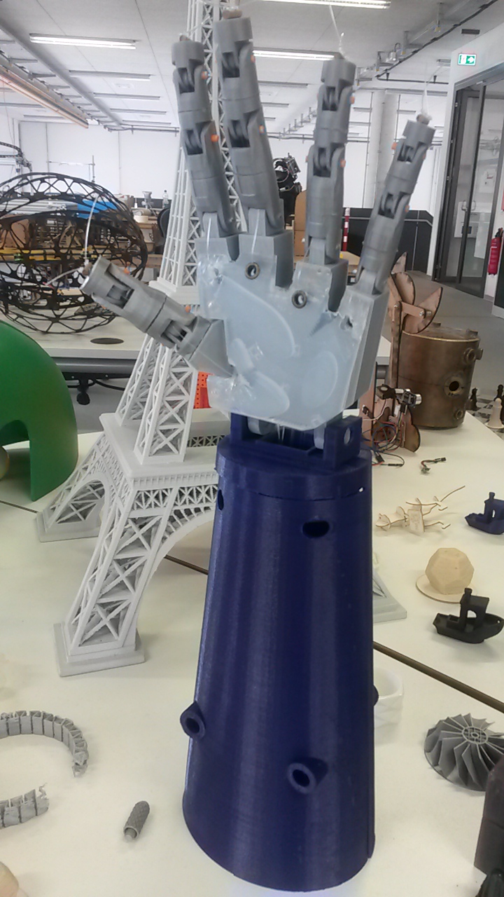
And here is the final result that I was so looking forward to!!!
Evaluation
The deadline for the success of this project was the day of the presentation, which was met successfully as it was ready earlier. All the tasks in mind were completed except for one. I wanted the hand depending on the different ranges the myosensor gets, to do different tasks like fist, pinch etc. So, my only remaining task is to figure this out but that will be developed after Fab Academy as there is not enough time left.
After a couple of failed trials with the design of the final project as described throughout the development of the project, it finally worked properly except for one finger where I should increase the tension of the fishing line between the tip of the it and the servo in which it is tied to. Also, the electronics of the project worked successfully from the first time and thankfully had to face no problems there.
Overall, the goals I had in mind for this project were 80% met and the questions still to be answered is when will the remaining part of my project be accomplished and I would like to answer with soon! :)
Throughout these months, I have learnt quick problem solving, the use of method combinations in order to achieve in this instance my prosthetic hand and a lot more valuable lessons!!
Downloads
As mentioned before, the fingers were taken from an open source project so I only have them as .stl files. Also, the whole hand design, from the palm, to the forearm, to the milling for the silicon grip are all in one file.
Auriculaire.stl | Index.stl | Thumb.stl | Majeure.stl | Ringfinger.stl
WireSlot.dxf | Servo_support.dxf
FABsthetics.sch | FABsthetics.brb | External_path.png | Internal_path.png
I would like to say a big THANK YOU to Daniele Ingrassia for his support and patience, to Karsten Nebe for making it possible to work in the lab even on Sundays, to all my fellow colleagues of Fab Academy this year (Ahmed Belal, Dumitru Albot, Konstantin Stamatopoulos, Cesar Mariscal, Jörn Kiwit) for their help here and there and of course to Adriana Cabrera for her insight regarding my project. It has been a great half of the year and I learnt so much!!! :) Again, AN HONEST THANK YOU!! I DO APPRECIATE EVERYTHING!!!