FINAL PROJECT - ELECTRONICS
CONTENTS
Click on any of the links below to see further details about the final project.
- Project management: Checklist of the project's gradual development.
- Concept: General draft of the first conceived idea.
- 2D/3D design: Summary and steps of the design process.
- Electronic production and design: Details, design and production of the main board for the project.
- 3D printing, laser cutting and prototyping: Further details about the production of the robot's parts.
- Embedded, application and interface programming: Networking, motor control and web interface.
- Final project summary: Video demonstration, bill of materials, files of the final robot and general summary.
BOARDS SUMMARY
jca4880 v1.0 - board is based on Gianluca Pugliese's board.
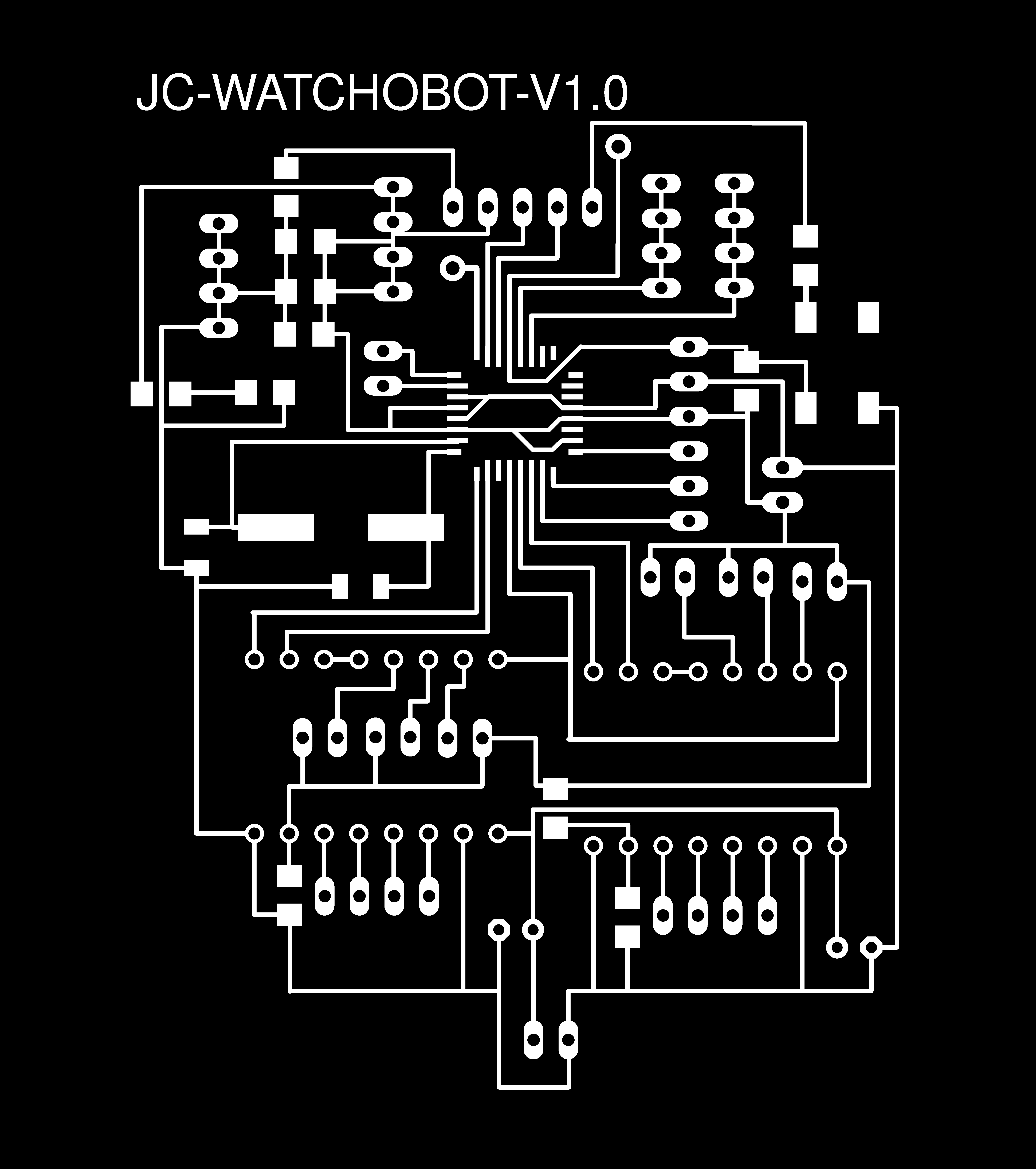
jc-watchobot v1.0 Board designed from scratch and based on the lessons learnt from designing jca4880 and satshakit.
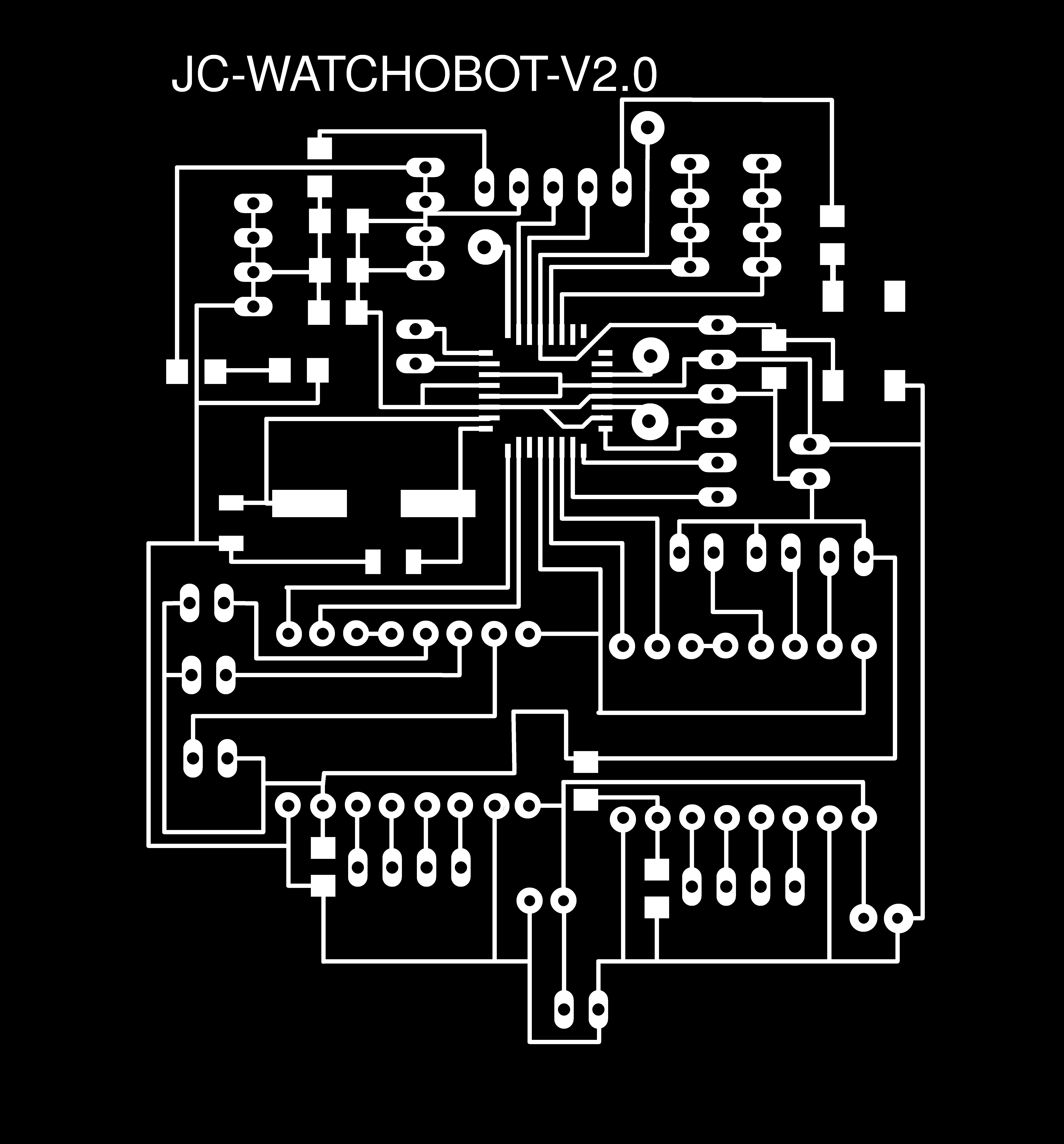
jc-watchobot v2.0 Re-design of v1.0, traces for the female headers are and general layout is improved. Some pins are added too.
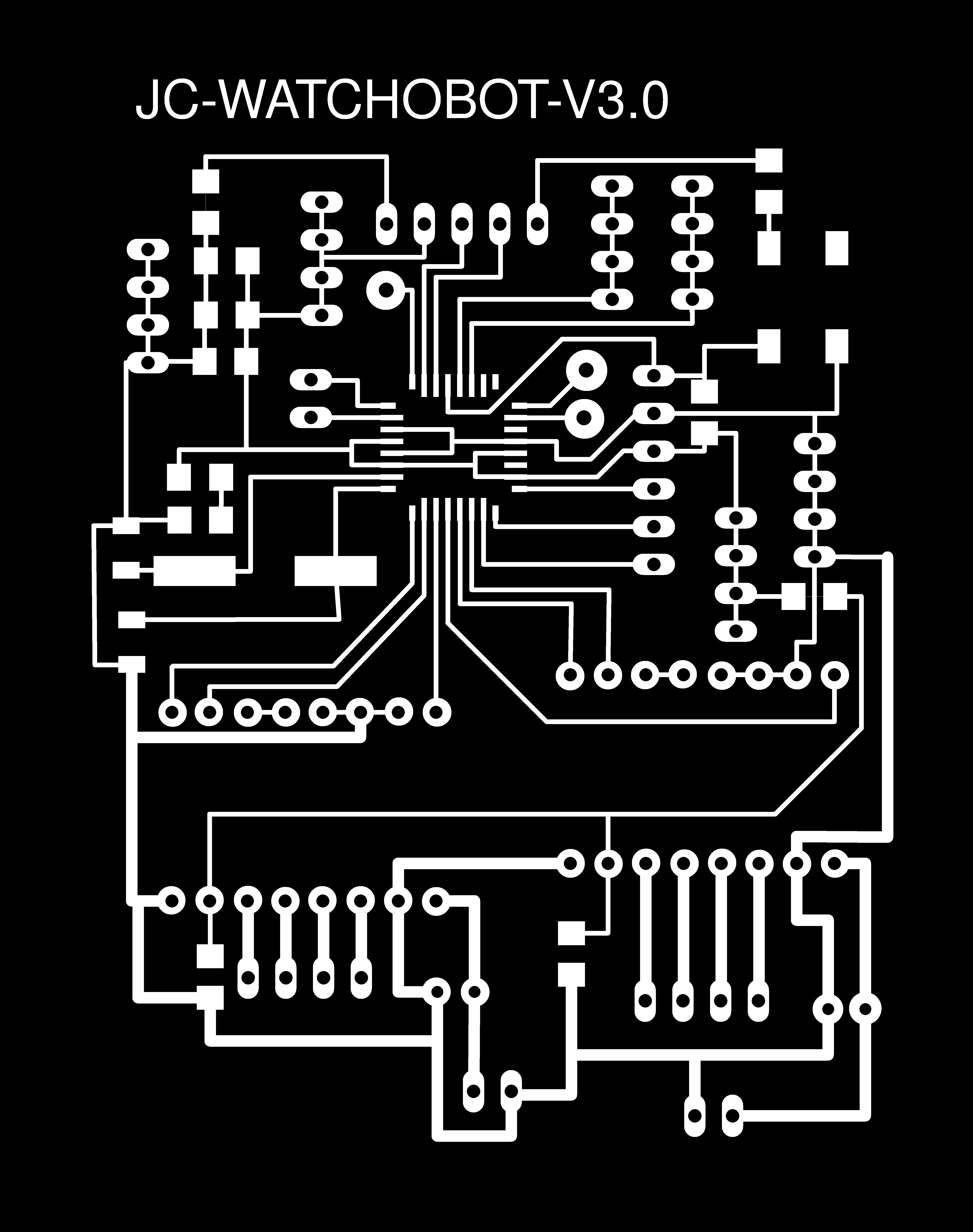
jc-watchobot v3.0Several changes over v2.0. Improved trace widths for the pololu carriers, enable pin for each carrier, extra digital pins, re-routed design and motors are in full-step mode by default.
jca4880 stepper board v1.0
This board design is based on the schematic of Gianluca Pugliese.
Board is able to control 2 stepper motors. It has extra pin-outs for sensors and a servo motor.
Board uses two A4988 stepper motor driver carriers.
The A4988 is a microstepping bipolar stepper motor driver. It has current limiting, over-current and over-temperature protection.
Headers of the A4988 can be connected to 0.1'' female connectors. Driver can be connected a a microcontroller following the following wiring diagram (copyright Pololu.com):

Logic supply voltage between 3 to 5.5V is connected across GND and VDD pins. A motor supply voltage between 8 to 35 V is connected across GND and VMOT. A 47µF capacitor is connected between VMOT and ground, it is to prevent LC voltage spikes to damage the board.
Similarly, decoupling capacitors are also needed for other supplies, with capacity to deliver peaks up to 4A for the motor supply.
Microstep size can be controlled by setting MS1, MS2, MS3 inputs. Table below summarizes the configurations:
MS1	MS2	MS3	MICROSTEP
---------------------------------
LOW	LOW	LOW	Full step
HIGH	LOW	LOW	Half step
LOW	HIGH	LOW	1/4 step
HIGH	HIGH	LOW	1/8 step
HIGH	HIGH	HIGH	1/16 step
The chip has 3 inputs for power state control: RST, SLP and EN.
The STEP and DIR inputs correspond to one microstep and direction, these pins do not have pull-up resistors and should not be left floating.
The trimmer potentiometer on the A4988 is used to set current limit. Note that when setting current limit, current must not be measured at the power supply but with a current meter in series with a stepper motor coil.
Following these considerations, board is routed and design following Gianluca's example board.

Detailed schematic:

Same steps are followed as here to export the inner and outer traces to .png format.


MILLING
Board is milled with Roland MDX-40A.
- FabModules is used to convert png image to rml and trace path.
- Settings for the inner cut with a 0.2mm tool are:
Cut depth = 0mm
Tool diameter = 0.2mm
Number of offsets = 4
Offset overlap = 55%
Path error = 1.1 pixels
Image threshold = 0.5

cut depth = 2mm
tool diameter = 1mm
number of offsets = 1
offset overlap = 50%
First cut did not come as expected, I went in too deep and traces were thin.

Hence, I modified the design in Inkscape to delete problematic areas:

Second milling came out perfect. However, I mistakenly launched the job for the outer cut without calculating the path first in FabModules.
The result was a perfect milled board cut in half.
Third try was successful.
I cleaned the board with isopropyl alcohol.

I drilled the holes manually.

Soldered components:

jc-watchobot v1.0
Note: for this board to work with 2 pololu carriers, one of the decoupling capacitors must be replaced by another vmot/gnd pair of pins.
Following design considerations of the pololu a4880 and my experience with the Satshakit (Daniele Ingrassia)and the design and soldering of the jc-a4880 board (based on Gianluca Pugliese's board).
I worked on a new design from scratch to improve the board.
This board is also based on the ATMEGA 328P-AU.
It drives two pololu a4880 drivers and has some extra pins to control e.g. a servo motor.
A 16mhz crystal is connected to PB6, PB7 with two 22pF capacitors. A green LED for power and a switch button with a pull-up resistor to the reset pin.
Board also includes ICSP and FTDI pins, SDA, SCL pins; as well as VCC and GND pins.
The board schematic (click to magnify):

The board design:

The board was milled using the Roland MDX-40A with same settings as the jc-a4880 board above.
Inner cut I used a 0.2mm tooltip with the following settings:
Cut depth = 0mm
Tool diameter = 0.2mm
Number of offsets = 4
Offset overlap = 55%
Path error = 1.1 pixels
Image threshold = 0.5
For the outer cut, as my board was moved out of the bed, I used a saw machine.
Next, I proceeded to solder the board, starting with the microcontroller.
Final soldered board:

To test the board, I used an Arduino as ISP and uploaded a bootloader accordingly through ICSP.
/home/jc/Program Files/arduino-1.6.13/hardware/tools/avr/bin/avrdude -C/home/jc/Program Files/arduino-1.6.13/hardware/tools/avr/etc/avrdude.conf -v -patmega328p -cstk500v1 -P/dev/ttyACM3 -b19200 -e -Ulock:w:0x3F:m -Uefuse:w:0x05:m -Uhfuse:w:0xDE:m -Ulfuse:w:0xFF:m

avrdude: Version 6.3, compiled on Sep 12 2016 at 15:21:49
         Copyright (c) 2000-2005 Brian Dean, http://www.bdmicro.com/
         Copyright (c) 2007-2014 Joerg Wunsch

         System wide configuration file is "/home/jc/Program Files/arduino-1.6.13/hardware/tools/avr/etc/avrdude.conf"
         User configuration file is "/home/jc/.avrduderc"
         User configuration file does not exist or is not a regular file, skipping

         Using Port                    : /dev/ttyACM3
         Using Programmer              : stk500v1
         Overriding Baud Rate          : 19200
         AVR Part                      : ATmega328P
         Chip Erase delay              : 9000 us
         PAGEL                         : PD7
         BS2                           : PC2
         RESET disposition             : dedicated
         RETRY pulse                   : SCK
         serial program mode           : yes
         parallel program mode         : yes
         Timeout                       : 200
         StabDelay                     : 100
         CmdexeDelay                   : 25
         SyncLoops                     : 32
         ByteDelay                     : 0
         PollIndex                     : 3
         PollValue                     : 0x53
         Memory Detail                 :

                                  Block Poll               Page                       Polled
           Memory Type Mode Delay Size  Indx Paged  Size   Size #Pages MinW  MaxW   ReadBack
           ----------- ---- ----- ----- ---- ------ ------ ---- ------ ----- ----- ---------
           eeprom        65    20     4    0 no       1024    4      0  3600  3600 0xff 0xff
           flash         65     6   128    0 yes     32768  128    256  4500  4500 0xff 0xff
           lfuse          0     0     0    0 no          1    0      0  4500  4500 0x00 0x00
           hfuse          0     0     0    0 no          1    0      0  4500  4500 0x00 0x00
           efuse          0     0     0    0 no          1    0      0  4500  4500 0x00 0x00
           lock           0     0     0    0 no          1    0      0  4500  4500 0x00 0x00
           calibration    0     0     0    0 no          1    0      0     0     0 0x00 0x00
           signature      0     0     0    0 no          3    0      0     0     0 0x00 0x00

         Programmer Type : STK500
         Description     : Atmel STK500 Version 1.x firmware
         Hardware Version: 2
         Firmware Version: 1.18
         Topcard         : Unknown
         Vtarget         : 0.0 V
         Varef           : 0.0 V
         Oscillator      : Off
         SCK period      : 0.1 us

avrdude: AVR device initialized and ready to accept instructions

Reading | ################################################## | 100% 0.02s

avrdude: Device signature = 0x1e950f (probably m328p)
avrdude: erasing chip
avrdude: reading input file "0x3F"
avrdude: writing lock (1 bytes):

Writing | ################################################## | 100% 0.01s

avrdude: 1 bytes of lock written
avrdude: verifying lock memory against 0x3F:
avrdude: load data lock data from input file 0x3F:
avrdude: input file 0x3F contains 1 bytes
avrdude: reading on-chip lock data:

Reading | ################################################## | 100% 0.01s

avrdude: verifying ...
avrdude: 1 bytes of lock verified
avrdude: reading input file "0x05"
avrdude: writing efuse (1 bytes):

Writing |  ***failed;
################################################## | 100% 0.07s

avrdude: 1 bytes of efuse written
avrdude: verifying efuse memory against 0x05:
avrdude: load data efuse data from input file 0x05:
avrdude: input file 0x05 contains 1 bytes
avrdude: reading on-chip efuse data:

/home/jc/Program Files/arduino-1.6.13/hardware/tools/avr/bin/avrdude -C/home/jc/Program Files/arduino-1.6.13/hardware/tools/avr/etc/avrdude.conf -v -patmega328p -cstk500v1 -P/dev/ttyACM3 -b19200 -Uflash:w:/home/jc/Program Files/arduino-1.6.13/hardware/arduino/avr/bootloaders/optiboot/optiboot_atmega328.hex:i -Ulock:w:0x0F:m

avrdude: Version 6.3, compiled on Sep 12 2016 at 15:21:49
         Copyright (c) 2000-2005 Brian Dean, http://www.bdmicro.com/
         Copyright (c) 2007-2014 Joerg Wunsch

         System wide configuration file is "/home/jc/Program Files/arduino-1.6.13/hardware/tools/avr/etc/avrdude.conf"
Reading | ################################################## | 100% 0.01s

avrdude: verifying ...
avrdude: WARNING: invalid value for unused bits in fuse "efuse", should be set to 1 according to datasheet
This behaviour is deprecated and will result in an error in future version
You probably want to use 0xfd instead of 0x05 (double check with your datasheet first).
avrdude: 1 bytes of efuse verified
avrdude: reading input file "0xDE"
avrdude: writing hfuse (1 bytes):

Writing | ################################################## | 100% 0.02s

avrdude: 1 bytes of hfuse written
avrdude: verifying hfuse memory against 0xDE:
avrdude: load data hfuse data from input file 0xDE:
avrdude: input file 0xDE contains 1 bytes
avrdude: reading on-chip hfuse data:

Reading | ################################################## | 100% 0.01s

avrdude: verifying ...
avrdude: 1 bytes of hfuse verified
avrdude: reading input file "0xFF"
avrdude: writing lfuse (1 bytes):

Writing | ################################################## | 100% 0.02s

avrdude: 1 bytes of lfuse written
avrdude: verifying lfuse memory against 0xFF:
avrdude: load data lfuse data from input file 0xFF:
avrdude: input file 0xFF contains 1 bytes
avrdude: reading on-chip lfuse data:

Reading | ################################################## | 100% 0.01s

avrdude: verifying ...
avrdude: 1 bytes of lfuse verified

avrdude done.  Thank you.

         User configuration file is "/home/jc/.avrduderc"
         User configuration file does not exist or is not a regular file, skipping

         Using Port                    : /dev/ttyACM3
         Using Programmer              : stk500v1
         Overriding Baud Rate          : 19200
         AVR Part                      : ATmega328P
         Chip Erase delay              : 9000 us
         PAGEL                         : PD7
         BS2                           : PC2
         RESET disposition             : dedicated
         RETRY pulse                   : SCK
         serial program mode           : yes
         parallel program mode         : yes
         Timeout                       : 200
         StabDelay                     : 100
         CmdexeDelay                   : 25
         SyncLoops                     : 32
         ByteDelay                     : 0
         PollIndex                     : 3
         PollValue                     : 0x53
         Memory Detail                 :

                                  Block Poll               Page                       Polled
           Memory Type Mode Delay Size  Indx Paged  Size   Size #Pages MinW  MaxW   ReadBack
           ----------- ---- ----- ----- ---- ------ ------ ---- ------ ----- ----- ---------
           eeprom        65    20     4    0 no       1024    4      0  3600  3600 0xff 0xff
           flash         65     6   128    0 yes     32768  128    256  4500  4500 0xff 0xff
           lfuse          0     0     0    0 no          1    0      0  4500  4500 0x00 0x00
           hfuse          0     0     0    0 no          1    0      0  4500  4500 0x00 0x00
           efuse          0     0     0    0 no          1    0      0  4500  4500 0x00 0x00
           lock           0     0     0    0 no          1    0      0  4500  4500 0x00 0x00
           calibration    0     0     0    0 no          1    0      0     0     0 0x00 0x00
           signature      0     0     0    0 no          3    0      0     0     0 0x00 0x00

         Programmer Type : STK500
         Description     : Atmel STK500 Version 1.x firmware
         Hardware Version: 2
         Firmware Version: 1.18
         Topcard         : Unknown
         Vtarget         : 0.0 V
         Varef           : 0.0 V
         Oscillator      : Off
         SCK period      : 0.1 us

avrdude: AVR device initialized and ready to accept instructions

Reading | ################################################## | 100% 0.02s

avrdude: Device signature = 0x1e950f (probably m328p)
avrdude: NOTE: "flash" memory has been specified, an erase cycle will be performed
         To disable this feature, specify the -D option.
avrdude: erasing chip
avrdude: reading input file "/home/jc/Program Files/arduino-1.6.13/hardware/arduino/avr/bootloaders/optiboot/optiboot_atmega328.hex"
avrdude: writing flash (32768 bytes):

Writing | ################################################## | 100% 0.00s

avrdude: 32768 bytes of flash written
avrdude: verifying flash memory against /home/jc/Program Files/arduino-1.6.13/hardware/arduino/avr/bootloaders/optiboot/optiboot_atmega328.hex:
avrdude: load data flash data from input file /home/jc/Program Files/arduino-1.6.13/hardware/arduino/avr/bootloaders/optiboot/optiboot_atmega328.hex:
avrdude: input file /home/jc/Program Files/arduino-1.6.13/hardware/arduino/avr/bootloaders/optiboot/optiboot_atmega328.hex contains 32768 bytes
avrdude: reading on-chip flash data:

Reading | ################################################## | 100% 0.00s

avrdude: verifying ...
avrdude: 32768 bytes of flash verified
avrdude: reading input file "0x0F"
avrdude: writing lock (1 bytes):

Writing | ################################################## | 100% 0.02s

avrdude: 1 bytes of lock written
avrdude: verifying lock memory against 0x0F:
avrdude: load data lock data from input file 0x0F:
avrdude: input file 0x0F contains 1 bytes
avrdude: reading on-chip lock data:

Reading | ################################################## | 100% 0.01s

avrdude: verifying ...
avrdude: 1 bytes of lock verified

avrdude done.  Thank you.
jc-watchobot-v2.0
Note: for this board to work with 2 pololu carriers, one of the decoupling capacitors must be replaced by another vmot/gnd pair of pins.
Board is an improvement of the v.1.0 version, layout is improved and extra adc6 and adc7 pins are added.
Some pin-header packages are changed to fit the cnc-milling process better.

The final layout of the board:

Pictures below show the differences in trace sizes for the jc-watchobot-v1.0 and the v2.0.
Board is milled using Roland MDX40a and Fab Modules as previous boards. The only difference was in the settings:
===============
INNER CUT
==============
Cut depth = 0mm
Tool diameter = 0.2mm
Number of offsets = 3
Offset overlap = 55%
Path error = 1.1 pixels
Image threshold = 0.5
Final milled board:

And how the board looked after soldering:
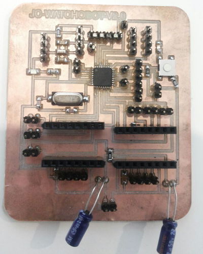
Note picture above, a 0-ohm resistor was soldered to a button to bridge a connection problem as one trace was broken by the hot-soldering iron, which was left too long on the trace while soldering the button.
I burned the bootloader using Arduino IDE:
/home/jc/Program Files/arduino-1.8.2/hardware/tools/avr/bin/avrdude -C/home/jc/Program Files/arduino-1.8.2/hardware/tools/avr/etc/avrdude.conf -v -patmega328p -cstk500v1 -P/dev/ttyACM3 -b19200 -e -Ulock:w:0x3F:m -Uefuse:w:0xFD:m -Uhfuse:w:0xDE:m -Ulfuse:w:0xFF:m

avrdude: Version 6.3, compiled on Jan 17 2017 at 11:00:16
         Copyright (c) 2000-2005 Brian Dean, http://www.bdmicro.com/
         Copyright (c) 2007-2014 Joerg Wunsch

         System wide configuration file is "/home/jc/Program Files/arduino-1.8.2/hardware/tools/avr/etc/avrdude.conf"
         User configuration file is "/home/jc/.avrduderc"
         User configuration file does not exist or is not a regular file, skipping

         Using Port                    : /dev/ttyACM3
         Using Programmer              : stk500v1
         Overriding Baud Rate          : 19200
         AVR Part                      : ATmega328P
         Chip Erase delay              : 9000 us
         PAGEL                         : PD7
         BS2                           : PC2
         RESET disposition             : dedicated
         RETRY pulse                   : SCK
         serial program mode           : yes
         parallel program mode         : yes
         Timeout                       : 200
         StabDelay                     : 100
         CmdexeDelay                   : 25
         SyncLoops                     : 32
         ByteDelay                     : 0
         PollIndex                     : 3
         PollValue                     : 0x53
         Memory Detail                 :

                                  Block Poll               Page                       Polled
           Memory Type Mode Delay Size  Indx Paged  Size   Size #Pages MinW  MaxW   ReadBack
           ----------- ---- ----- ----- ---- ------ ------ ---- ------ ----- ----- ---------
           eeprom        65    20     4    0 no       1024    4      0  3600  3600 0xff 0xff
           flash         65     6   128    0 yes     32768  128    256  4500  4500 0xff 0xff
           lfuse          0     0     0    0 no          1    0      0  4500  4500 0x00 0x00
           hfuse          0     0     0    0 no          1    0      0  4500  4500 0x00 0x00
           efuse          0     0     0    0 no          1    0      0  4500  4500 0x00 0x00
           lock           0     0     0    0 no          1    0      0  4500  4500 0x00 0x00
           calibration    0     0     0    0 no          1    0      0     0     0 0x00 0x00
           signature      0     0     0    0 no          3    0      0     0     0 0x00 0x00

         Programmer Type : STK500
         Description     : Atmel STK500 Version 1.x firmware
         Hardware Version: 2
         Firmware Version: 1.18
         Topcard         : Unknown
         Vtarget         : 0.0 V
         Varef           : 0.0 V
         Oscillator      : Off
         SCK period      : 0.1 us

avrdude: AVR device initialized and ready to accept instructions

Reading | ################################################## | 100% 0.02s

avrdude: Device signature = 0x1e950f (probably m328p)
avrdude: erasing chip
avrdude: reading input file "0x3F"
avrdude: writing lock (1 bytes):

Writing | ################################################## | 100% 0.01s

avrdude: 1 bytes of lock written
avrdude: verifying lock memory against 0x3F:
avrdude: load data lock data from input file 0x3F:
avrdude: input file 0x3F contains 1 bytes
avrdude: reading on-chip lock data:

Reading | ################################################## | 100% 0.01s

avrdude: verifying ...
avrdude: 1 bytes of lock verified
avrdude: reading input file "0xFD"
avrdude: writing efuse (1 bytes):

Writing | ################################################## | 100% 0.02s

avrdude: 1 bytes of efuse written
avrdude: verifying efuse memory against 0xFD:
avrdude: load data efuse data from input file 0xFD:
avrdude: input file 0xFD contains 1 bytes
avrdude: reading on-chip efuse data:

Reading | ################################################## | 100% 0.01s

avrdude: verifying ...
avrdude: 1 bytes of efuse verified
avrdude: reading input file "0xDE"
avrdude: writing hfuse (1 bytes):

Writing | ################################################## | 100% 0.02s

avrdude: 1 bytes of hfuse written
avrdude: verifying hfuse memory against 0xDE:
avrdude: load data hfuse data from input file 0xDE:
avrdude: input file 0xDE contains 1 bytes
avrdude: reading on-chip hfuse data:

Reading | ################################################## | 100% 0.01s

avrdude: verifying ...
avrdude: 1 bytes of hfuse verified
avrdude: reading input file "0xFF"
avrdude: writing lfuse (1 bytes):

/home/jc/Program Files/arduino-1.8.2/hardware/tools/avr/bin/avrdude -C/home/jc/Program Files/arduino-1.8.2/hardware/tools/avr/etc/avrdude.conf -v -patmega328p -cstk500v1 -P/dev/ttyACM3 -b19200 -Uflash:w:/home/jc/Program Files/arduino-1.8.2/hardware/arduino/avr/bootloaders/optiboot/optiboot_atmega328.hex:i -Ulock:w:0x0F:m

avrdude: Version 6.3, compiled on Jan 17 2017 at 11:00:16
         Copyright (c) 2000-2005 Brian Dean, http://www.bdmicro.com/
         Copyright (c) 2007-2014 Joerg Wunsch

         System wide configuration file is "/home/jc/Program Files/arduino-1.8.2/hardware/tools/avr/etc/avrdude.conf"
         User configuration file is "/home/jc/.avrduderc"
         User configuration file does not exist or is not a regular file, skipping

         Using Port                    : /dev/ttyACM3
         Using Programmer              : stk500v1
         Overriding Baud Rate          : 19200
Writing | ################################################## | 100% 0.02s

avrdude: 1 bytes of lfuse written
avrdude: verifying lfuse memory against 0xFF:
avrdude: load data lfuse data from input file 0xFF:
avrdude: input file 0xFF contains 1 bytes
avrdude: reading on-chip lfuse data:

Reading | ################################################## | 100% 0.01s

avrdude: verifying ...
avrdude: 1 bytes of lfuse verified

avrdude done.  Thank you.

         AVR Part                      : ATmega328P
         Chip Erase delay              : 9000 us
         PAGEL                         : PD7
         BS2                           : PC2
         RESET disposition             : dedicated
         RETRY pulse                   : SCK
         serial program mode           : yes
         parallel program mode         : yes
         Timeout                       : 200
         StabDelay                     : 100
         CmdexeDelay                   : 25
         SyncLoops                     : 32
         ByteDelay                     : 0
         PollIndex                     : 3
         PollValue                     : 0x53
         Memory Detail                 :

                                  Block Poll               Page                       Polled
           Memory Type Mode Delay Size  Indx Paged  Size   Size #Pages MinW  MaxW   ReadBack
           ----------- ---- ----- ----- ---- ------ ------ ---- ------ ----- ----- ---------
           eeprom        65    20     4    0 no       1024    4      0  3600  3600 0xff 0xff
           flash         65     6   128    0 yes     32768  128    256  4500  4500 0xff 0xff
           lfuse          0     0     0    0 no          1    0      0  4500  4500 0x00 0x00
           hfuse          0     0     0    0 no          1    0      0  4500  4500 0x00 0x00
           efuse          0     0     0    0 no          1    0      0  4500  4500 0x00 0x00
           lock           0     0     0    0 no          1    0      0  4500  4500 0x00 0x00
           calibration    0     0     0    0 no          1    0      0     0     0 0x00 0x00
           signature      0     0     0    0 no          3    0      0     0     0 0x00 0x00

         Programmer Type : STK500
         Description     : Atmel STK500 Version 1.x firmware
         Hardware Version: 2
         Firmware Version: 1.18
         Topcard         : Unknown
         Vtarget         : 0.0 V
         Varef           : 0.0 V
         Oscillator      : Off
         SCK period      : 0.1 us

avrdude: AVR device initialized and ready to accept instructions

Reading | ################################################## | 100% 0.02s

avrdude: Device signature = 0x1e950f (probably m328p)
avrdude: NOTE: "flash" memory has been specified, an erase cycle will be performed
         To disable this feature, specify the -D option.
avrdude: erasing chip
avrdude: reading input file "/home/jc/Program Files/arduino-1.8.2/hardware/arduino/avr/bootloaders/optiboot/optiboot_atmega328.hex"
avrdude: writing flash (32768 bytes):

Writing | ################################################## | 100% 0.00s

avrdude: 32768 bytes of flash written
avrdude: verifying flash memory against /home/jc/Program Files/arduino-1.8.2/hardware/arduino/avr/bootloaders/optiboot/optiboot_atmega328.hex:
avrdude: load data flash data from input file /home/jc/Program Files/arduino-1.8.2/hardware/arduino/avr/bootloaders/optiboot/optiboot_atmega328.hex:
avrdude: input file /home/jc/Program Files/arduino-1.8.2/hardware/arduino/avr/bootloaders/optiboot/optiboot_atmega328.hex contains 32768 bytes
avrdude: reading on-chip flash data:

Reading | ################################################## | 100% 0.00s

avrdude: verifying ...
avrdude: 32768 bytes of flash verified
avrdude: reading input file "0x0F"
avrdude: writing lock (1 bytes):

Writing | ################################################## | 100% 0.02s

avrdude: 1 bytes of lock written
avrdude: verifying lock memory against 0x0F:
avrdude: load data lock data from input file 0x0F:
avrdude: input file 0x0F contains 1 bytes
avrdude: reading on-chip lock data:

Reading | ################################################## | 100% 0.01s

avrdude: verifying ...
avrdude: 1 bytes of lock verified

avrdude done.  Thank you.
jc-watchobot v3.0
FOllowing low current coming out of the pololu drivers in v2.0, board width is changed at the pololu carriers. V_mot for each carrier is eadded with their respective de-coupling capacitors.
Picture below shows the new layout of the board.

Schematic below illustrates the changes (click to magnify):

Board is milled using Roland MDX40a, with similar settings as previously:
===============
INNER CUT
==============
speed: 8
Cut depth = 0mm
Tool diameter = 0.2mm
Number of offsets = 3
Offset overlap = 55%
Path error = 1.1 pixels
Image threshold = 0.5

===============
OUTER CUT
==============
speed: 0.4
cut depth:2.2mm
tool diameter: 1mm
number of offsets: 1
offset overlap: 55%
FILES
jc watchobot v1.0 inner traces
jc watchobot v1.0 outer traces
jc-watchobot v2.0 inner traces
jc-watchobot v2.0 outer traces
jc-watchobot v3.0 inner traces
jc-watchobot v3.0 outer traces