

Week 13 - Input devices
![]()
![]()
![]()
Measure something: add a sensor to a microcontroller board that you have designed and read it.
For this week I plan to read out a temperature and humidity sensor with a Fabkit, becouse it fits with my finalproject
![]()
![]()
Illustration of DHT22 from the data sheet:

Apply 10 kohm pre-resistor to the VCC Pin (Pin 1)!
![]()
Technical specifications:
![]()
![]()

![]()
you can find it here
DHT22 Datasheet
![]()
Required hardware for this assignment:
![]()
![]()
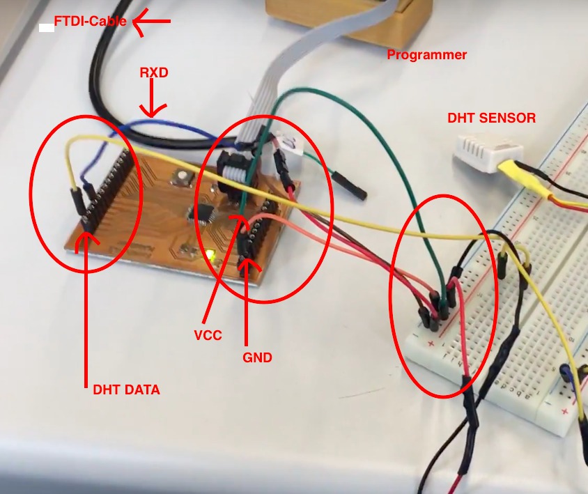
Wiring the board:
![]()
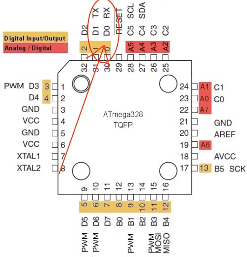
With the help of the following illustration I transform the ATmega 328 P-AU pins into the Arduino pins:

![]()
To simplify it with the pin assignment I have a document created, what my pins are directly designated:

![]()
I used a breadboard for wiring all together:
![]()

![]()
![]()
![]()
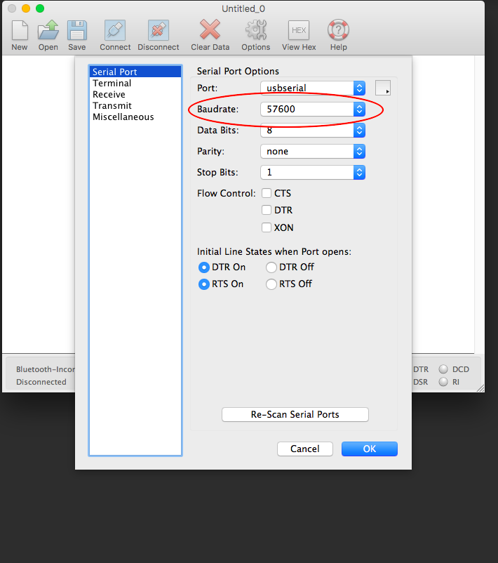
Be sure that you have installed this driver if you use the same FTDI-cable:
prolific driver.
As baudrate I have specified 57600 baud.
![]()
Modified Sketch for DHT READ
//**************************************************************+++++++++
//  Name    : DHT Test
//  Author  : Robert Jaenisch
//  Date    : 10 Feb, 2015
//  Modified:
//  Version : 1.0
//  URL     : http://deskfactory.de
//  Notes   : Programmcode zum Auslesen eines DHT Sensors. Der Ursprünglche
Code von Rob Tillaart wurde ins Deutsch übersetzt und die Ausgabe
zu besseren Lesbarkeit angepasst.
// Verweis auf den Original Code:

//    FILE: dht_test.ino
//  AUTHOR: Rob Tillaart
// VERSION: 0.1.07
// PURPOSE: DHT Temperature & Humidity Sensor library for Arduino
//     URL: http://arduino.cc/playground/Main/DHTLib
//
// Released to the public domain
//
//****************************************************************
// Lade die DHT Sensor Bibliothek
#include

dht DHT;


//  DHT11 Fabkit PIN 2
//#define DHT11_PIN 4
//#define DHT21_PIN 5
#define DHT22_PIN 4

int chk;

void setup()
{
  Serial.begin(57600);
  Serial.println("DHT TEST PROGRAM ");
  Serial.print("LIBRARY VERSION: ");
  Serial.println(DHT_LIB_VERSION);
  Serial.println();
}

void loop()
{
  // DHT22 Sensor Lesen

    Serial.print("Type: DHT22, \t");
    chk = DHT.read22(DHT22_PIN);
    switch (chk)
    {
      case DHTLIB_OK:
      Serial.print("Status: OK,\t");
      break;
      case DHTLIB_ERROR_CHECKSUM:
      Serial.print("Status: Checksum error,\t");
      break;
      case DHTLIB_ERROR_TIMEOUT:
      Serial.print("Status: Time out error,\t");
      break;
      default:
      Serial.print("Status: unbekannter Fehler,\t");
      break;
    }
     // Ausgabe über die serielle Schnittstelle
    Serial.print("relative Luftfeuchtigkeit (%): ");
    Serial.print(DHT.humidity, 1);
    Serial.print(",\tTemperatur (C)");
    Serial.println(DHT.temperature, 1);

    delay(1000);


    // Daten für den DHT21 lesen
    /*
    Serial.print("Type: DHT21, \t");
    chk = DHT.read21(DHT21_PIN);
    switch (chk)
    {
      case DHTLIB_OK:
      Serial.print("Status: OK,\t");
      break;
      case DHTLIB_ERROR_CHECKSUM:
      Serial.print("Status: Checksum error,\t");
      break;
      case DHTLIB_ERROR_TIMEOUT:
      Serial.print("Status: Time out error,\t");
      break;
      default:
      Serial.print("Status: unbekannter Fehler,\t");
      break;
    }
     // Ausgabe über die serielle Schnittstelle
    Serial.print("relative Luftfeuchtigkeit (%): ");
    Serial.print(DHT.humidity, 1);
    Serial.print(",\tTemperatur (C)");
    Serial.println(DHT.temperature, 1);

    delay(1000);
  */

  // Daten für den DHT11 Sensor lesen
 /* Serial.print("Type: DHT11, \t");
  chk = DHT.read11(DHT11_PIN);
  switch (chk)
  {
    case DHTLIB_OK:
    Serial.print("Status: OK,\t");
    break;
    case DHTLIB_ERROR_CHECKSUM:
    Serial.print("Status: Checksum error,\t");
    break;
    case DHTLIB_ERROR_TIMEOUT:
    Serial.print("Status: Time out error,\t");
    break;
    default:
    Serial.print("Status: unbekannter Fehler,\t");
    break;
  }
 // Ausgabe der Daten über die serielle Schnittstelle
    Serial.print("relative Luftfeuchtigkeit (%): ");
    Serial.print(DHT.humidity, 1);
    Serial.print(",\tTemperatur (C)");
    Serial.println(DHT.temperature, 1);

  delay(1000);  */
}
//
// ENDE

 }
![]()
![]()
Postscript/Additions:
At first it was important to add the source of my modificated code to the top of the sketch.
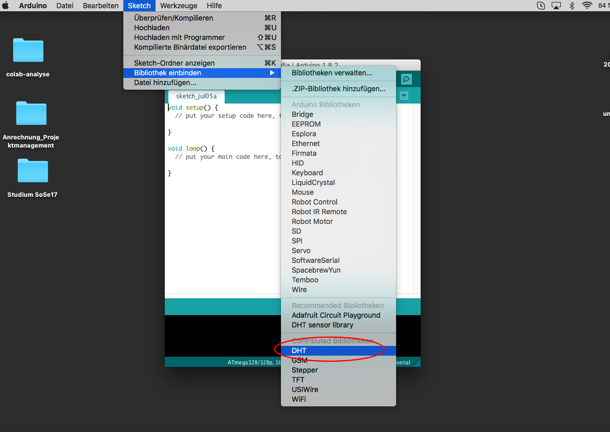
First step is to add the DHT Sensor Library from the Arduino IDE:
![]()
![]()
Now I explain a litle bit more of that code and what I learned:
#include // Add the DHT Sensor Library from the Arduino IDE
void setup() // This is where setup begins
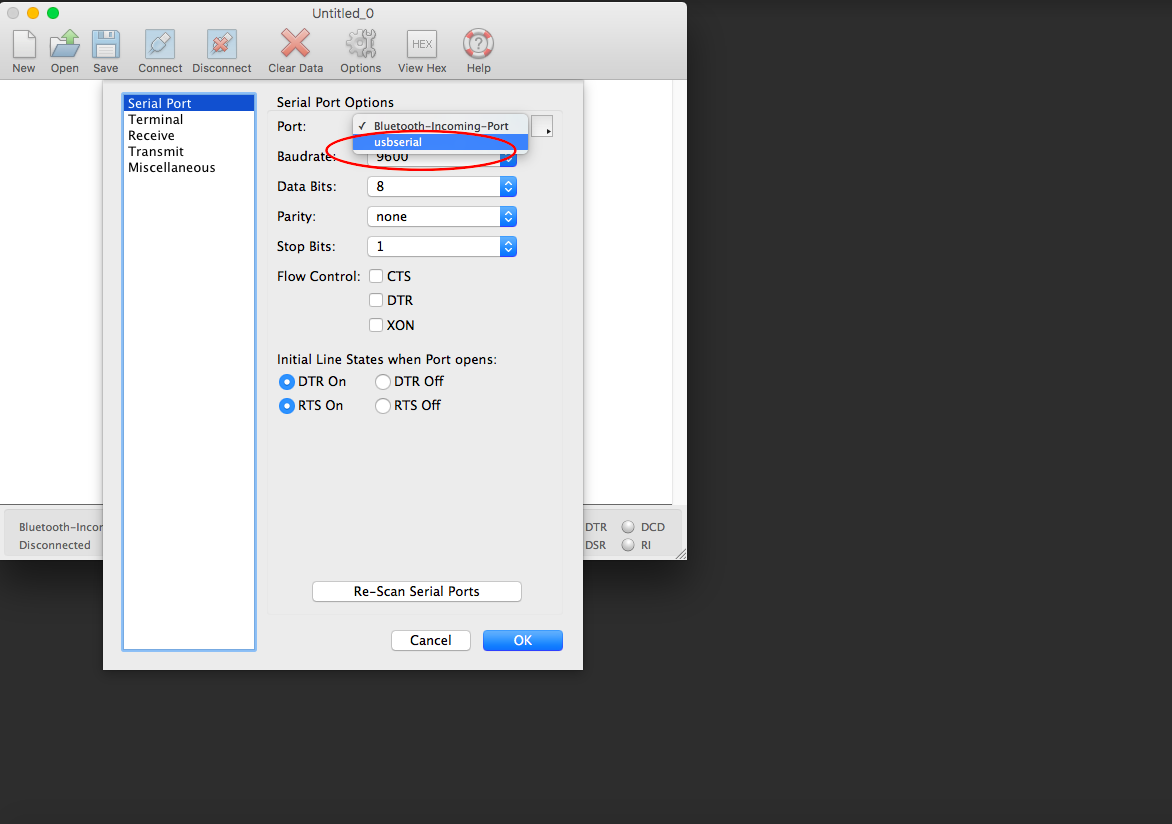
Start communication with the serial port. This is necessary to have the value read out in the "serial monitor" display (In my Case I use Coolterm with 57600 baud):
Serial.begin(57600);
void loop() // Here begins the main part
Serial.print // Output of the values via the serial interface
delay(1000); // Pauses the program (in miliseconds; there are 1000 milliseconds in a second.)
Tutorial for CoolTerm:
To let me view the data via a serial interface (FTDI cable) in addition to the Arduino serial monitor I have downloaded the software coolterm.
![]()
![]()
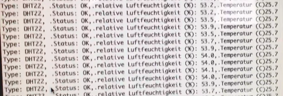
Here you can see the sensor values in the terminal of coolTerm:
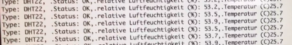
![]()
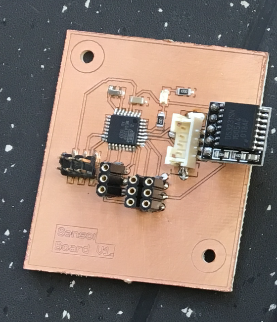
The wiring of the fabkit with the sensor and the Ftdi-cable (RXD pin) can be seen on the photo above.
![]()
![]()
Explaining of the Input analogRead(WatersensorPin) of my final:
Sensor-board on i2c bus adress = 20
![]()
![]()
![]()
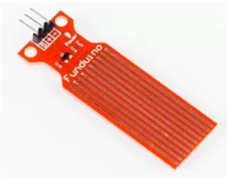
With a liquid sensor you can detect a liquid. For this purpose, the liquid must be located directly on the sensor. A small drop is sufficient to obtain a clear measured value.
In my final project I use this sensor to detect if there is enough water on the rock wool.
The functionality:
There is a voltage on the long contact points that pass through the sensor (either + or -). As soon as a liquid, for example, connects two contacts through a trop, a small current flows from one contact to the other. This value is electronically processed in the sensor and transmitted to an analog input of the board in the form of an analog signal.
It converts the voltage applied to the analogue pin into a numerical value. 0 to 5 volts corresponds to a numerical value from 0 to 1023 (This is 1024 numbers since the zero is counted as the first numerical value). In the case of the liquid sensor, the value in the dry state is zero "0". As soon as a drop of water hits the sensor contacts, the "Who" is at "480". The more drops are on the sensor, the higher the value.
int WatersensorPin = A3; // Analog pin where I connect the signal-pin of the sensor.
waterlevel.level = analogRead(WatersensorPin); // Reads the value from the specified analog pin. The voltage at the sensor is read out and stored under the variable "0". The ATmega328 P-AU board contains a analog to digital converter. This means that it will map input voltages between 0 and 5 volts into integer values between 0 and 1023. This is a resolution between readings of: 5 volts or 1024 units.
int WatersensorValue = 0; // variable to store the value coming from the watersensor
![]()
![]()
Download-Section:
![]()
![]()
![]()