Programming the board
Goals to reach
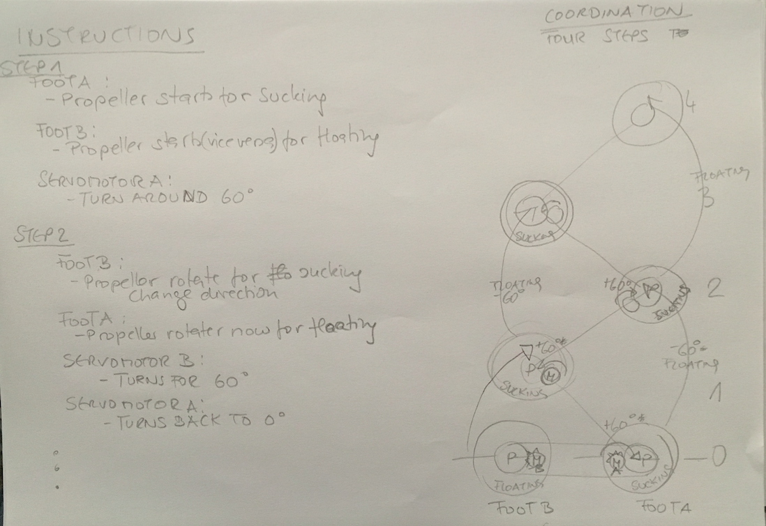
Via IR controlling a bunch of motors in a coordinated way. The task is: I press no. 1 on my remote control and my robot walk for about several steps forward. I press button no. 2 and my robot change it's orientation on a plane surface.Software development
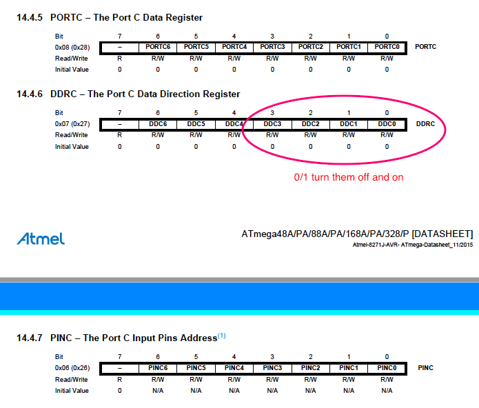
This sketch is based on Arduino's basic IRdemo sketch. I developed it step by step first the terms I need for IR (I deleted the Serialprint section as I didn´t want to use a monitor and waste running time), then I inserted plain C commands to turn on and off the pins for the air-screws. That is good to save executing time. Then I set stepwise the comands for servos. I had to take care about timing, reversion of polarity, and coordination of the movements. Also, I had to take care about the feature of these servos: they are limited to 180 degree. So had to calculate turning on vaccuming or floating, servo movement for walking, servo movement for returning back to zero, direction of servo rotation.The input for the C parts I got from webpages like this: maxembedded controlling dc motors with an h-bridge in C. I looked up in the datasheet of Atmega328p to find out where I can find these informations to be able to set the pins low and high.


Please find below the sketch for copying:
#include <boarddefs.h> // libraries I need

#include <IRremote.h>

#include <avr/io.h>

#include <Servo.h>

int ENLeft = 6;// h-bridgeEnablepin
int ENR = 5;// h-bridgeEnablepin
int RECV_PIN = 2; // pin for IR sensor

Servo servoLeft; //giving a name to the servos
Servo servoR;
const int LED = 8; //LED connected to digital pin8
IRrecv irrecv(RECV_PIN); //Creates the receiver object
decode_results results;//decodes incoming codes

void setup() {


  pinMode(LED, OUTPUT);// Outputpin
  digitalWrite(LED, LOW);
  servoLeft.attach(9);
  servoR.attach(10);
   DDRC = 0x0F; // all PC ports are activated for 2 air-screws
    pinMode (ENLeft, OUTPUT);//Outputpin
    pinMode (ENR, OUTPUT);//Outputpin
    analogWrite(ENLeft, 255);
    analogWrite(ENR, 255);
    PORTC = 0b00000000;// stops first all air-screws
    irrecv.enableIRIn();//Begin the receiving process.


}
void loop() {

   if (irrecv.decode(&results)) {

   if (results.value ==16724175) { //this code number is button #1#


    PORTC = 0b00000101; // PC0 =High, PC1=Low,PC2=High, PC3=Low (one direction) Propeller
    delay (500);
  digitalWrite(LED, HIGH);//Led on
  servoR.write(20);
  delay (500);
    servoLeft.write(150);
  delay(3000); //wait two seconds
  PORTC = 0b00001010; //PC0=Low, PC1=High, PC2=Low, Pc3=High (vice versa) Propeller
  delay (500);
  digitalWrite(LED, LOW); //Led off
  servoLeft.write(20);
  delay(3000);

  PORTC = 0b00000101; // PC0 =High, PC1=Low,PC2=High, PC3=Low (one direction) Propeller
    delay (500);
    digitalWrite(LED, HIGH);//Led on
    servoR.write(150);
    delay (500);
    servoLeft.write (150);
    delay(3000);
  PORTC = 0b00001010; //PC0=Low, PC1=High, PC2=Low, Pc3=High (vice versa) Propeller
    delay (500);
    digitalWrite(LED, LOW); //Led off
    servoLeft.write(20);
    delay (500);
    servoR.write(20);
    delay (3000);

  PORTC = 0b00000101; // PC0 =High, PC1=Low,PC2=High, PC3=Low (one direction) Propeller
    delay (500);
  digitalWrite(LED, HIGH);//Led on
  servoR.write(150);
  delay (500);
  servoLeft.write(150);
  delay(3000); //wait two seconds

  PORTC = 0b00001010; //PC0=Low, PC1=High, PC2=Low, Pc3=High (vice versa) Propeller
    delay (500);
    digitalWrite(LED, LOW); //Led off
    servoLeft.write(20);
    delay (500);
    servoR.write(20);
    delay (3000);

 PORTC = 0b00000101; // PC0 =High, PC1=Low,PC2=High, PC3=Low (one direction) Propeller
    delay (500);
  digitalWrite(LED, HIGH);//Led on
  servoR.write(150);
  delay (500);
  servoLeft.write(150);
  delay(3000); //wait two seconds

  PORTC = 0b00001010; //PC0=Low, PC1=High, PC2=Low, Pc3=High (vice versa) Propeller
    delay (500);
    digitalWrite(LED, LOW); //Led off
    servoLeft.write(20);
    delay (500);
    servoR.write(20);
    delay (3000);

  PORTC = 0b00000101; // PC0 =High, PC1=Low,PC2=High, PC3=Low (one direction) Propeller
    delay (500);
  digitalWrite(LED, HIGH);//Led on
  servoR.write(150);
  delay (500);
  servoLeft.write(150);
  delay(3000); //wait two seconds


  digitalWrite(LED, LOW); //Led off


    PORTC = 0b00000000; //stops both air-screws
   }


    if (results.value == 16718055) { //this code number is button #2#


    PORTC = 0b00000101; // PC0 =High, PC1=Low,PC2=High, PC3=Low (one direction) Propeller
    delay (500);
    digitalWrite(LED, HIGH);//Led on
    servoR.write(20);

    delay(3000);

  PORTC = 0b00001010; //PC0=Low, PC1=High, PC2=Low, Pc3=High (vice versa) Propeller
    delay (500);
    digitalWrite(LED, LOW); //Led off
    servoLeft.write(20);
    delay(500);
    servoR.write(150);
    delay (3000);

  PORTC = 0b00000101; // PC0 =High, PC1=Low,PC2=High, PC3=Low (one direction) Propeller
    delay (500);
    digitalWrite(LED, HIGH);//Led on
    servoR.write(20);
    delay(500);
    servoLeft.write(150);
    delay(3000);


  digitalWrite(LED,LOW);


    PORTC = 0b00000000;

    }
    irrecv.resume();//receiving the next value


   }
}
Download the Railbot File:
Railbot sketchFor a better understanding of the program above I had to be aware of the physical movements. In the beginning the robot just couldn't move foreward, it was 'treading water'. I had to find out that an early retraction can cause a countermovement. By realization this feature I inserted a delay between the active locomotion servo and the resetting servo, this delay helped to retract on an air-cussion without any effect on the walking process rather then touching the table. Alike I added a delay between air-screw start and moving servo.