Computer-Controlled Cutting all about cardboard cutting and vinyl design
Discover our laser cutter what can it do and what not
Teamwork discover together
Part Aleks: Kerf detection how thick is the laser
To find out the thickness and other characteristics of the laser-beam I followed three ways:
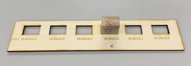
First, through drawing several rectangles with dimensions getting smaller in 0.10mm steps on a 3mm plywoodplate. From clearance fit til fit and press-fit;
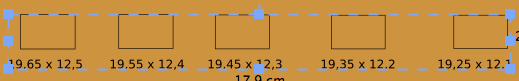
Here you can see rectangles opened in visicut with below dimensions in green for engraving.

Cutting settings and engraving settings.
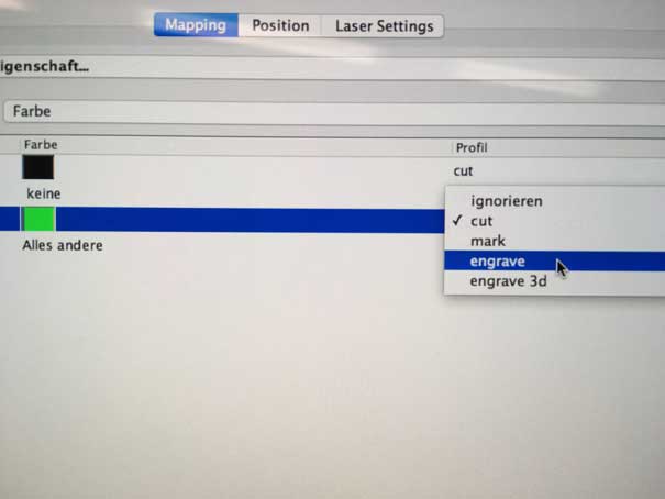
You choose the color you want to cut or engrave in characters. So you choose green for engraving the the dimension below the rectangles
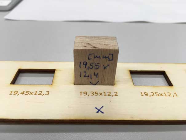
Here, you can see for pressfitting you need to reduce the cutting measures at 0,2 mm.
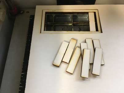
Second, through cutting out a rectangle frame with ten inner straight slices, measuring the total gap and dividing it by ten.
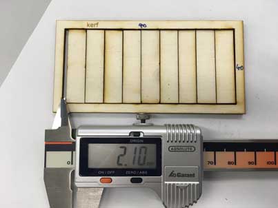

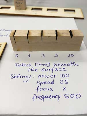
Third, through cutting several times into a bigger piece of wood (19.55 hight). By adjusting the focus in view steps we could find out more about the cone-shaped kerf. In Focus settings number 1 implies 1mm below surface.See Focus Settings.
Focus Settings
What happens to the cutting edge, if we vary the focus of the laser-beam? To answer this question we set the focus 0,1,3,5,10 mm beneath the surface of the wood material we wanted to cut. It is definitely interesting to see that 10mm focus cut is wide and very short (only 2mm deep) and the higher the focus the longer the slit.
Part Marcel: Power configuration how much power do we have

Power configuration raster, vector in wood and acryl
To test and to visualize the strength of the laser when engraving and vector cutting, I have made some test pieces in wood and acrylic as you can see on the previous photo.
I have engrave a piece of wood and a piece of acrylic with a scale in steps of 10% ascending from 10-100%. The respective engraving can be seen on the squares. You can see very clearly how the engraving is fired deeper and deeper into the material (Especially with wood).
Furthermore, I created a cheet-sheet for vector cutting in acrylic. You can see the depth, which ascend with increasing power deeper and deeper into the acrylic until it finally cuts at 40% power and 40 speed.


First I made a drawing in inkscape and selected the first square. Then click on extensions -> lasercut path -> open in Visicut.
All squares were selected one by one and increased by 10% power each.
The edge was colored red, so the program could see what was cut and what had to be engraved (color mapping).
Part Florian: Engrave images smoke generator
Because we cannot use the windows driver of the epilog laser because we do not have windows machines at the laboratory, we are using the software VisiCut to communicate with our laser-cutter.
We are using a epilog laser-cutter 50W at our FabLab at the Hochschule Ruhr West. Now to import my design to VisiCut I had to add my test images to Inkscape and using the VisiCut plugin to add the images and the additional text under the test image and a frame to cut everything to VisiCut.
We are using the VisiCut to send our designs from our computer to VisiCut. Here is also the place to set the properties for cutting job.


The following images show, that the test image is printed at 500 dpi. The second image show the print process. You can see that every line is burned at once line after line.


As the result of the engrave job you can see the differnece between the normal engrave and the 3D engrave job. In the normal engrave the only shades of intensity are an optical, when you have a pattern like black lines that are more or less close together. On the right side you see the 3D engrave. Here the intensity comes when the laser burns deeper into the material. Because you can see this as a greyscale representation of that image. There is no difference in color, only how intensive the color is. The result is a real 3D image. It looks like a translation to braille for images.
On top I engraved the screenshot of our FabAcademy FabLab site to demonstrate the 3D engrave ability in a real world example. As you can see there is a mix of images text and some gradients.
I looked inside the cutter documentation to find out a configuration for my 4mm thick compressed wood. So I chose the following configuration.
| type | power | speed | focus | dpi |
|---|---|---|---|---|
| engrave 3D | 100 | 80 | 0 | 500 |
I made a small video from the engrave process. There is a difference when you have a vector bases job and a raster based one. You can see the difference in the print process where we here look at a raster based engrave job. You can see that the laser cutter is cutting line by line. Have a look at my video about the pressfit construction. You can see that the cutter does a vector based job and moves more on the y axis of the print-area.
Here you can see the result of the engrave job. When looking at the result from above it looks like a brown grayscale image but from the side you can see how the laser burns at several layers to simulate the the color intensities.

