
WEEK 8 (15 March 2017)
[Embedded Programming]
This week the embedded programming assignment is to program the hello board...I must, program it and test it.
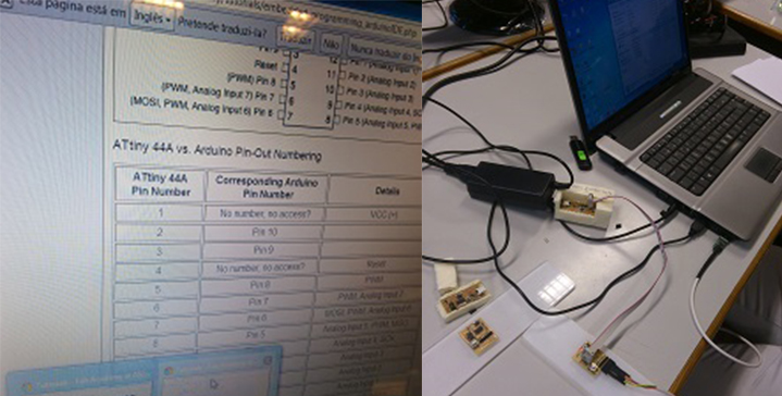
Datasheets, are instruction manuals for electronic components, they explain exactly what a component does and how to use it.
Content:
The first page is usually a summary of the function and features of the component. You can quickly find a description of the functionality, the basic specifications (numbers that describe what a component needs/can do and sometimes a functional block diagram that shows the internal functions).
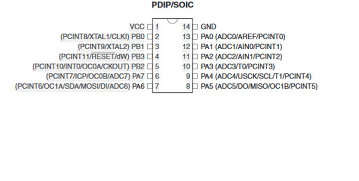
Pinout lists the component's pins, their functions, and where they’re physically located on the component.
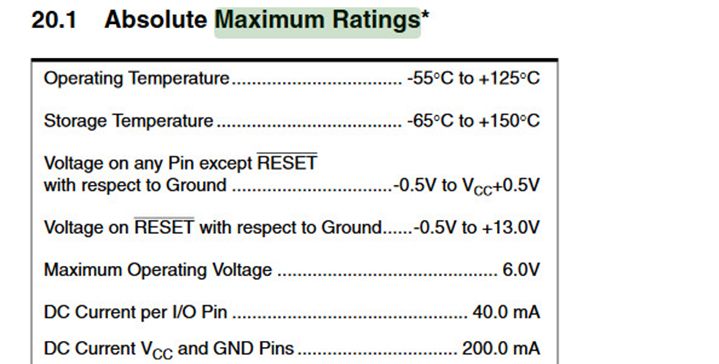
Tables of Elecrical specifications, this will list the absolute maximum ratings a component can handle before damaging it.
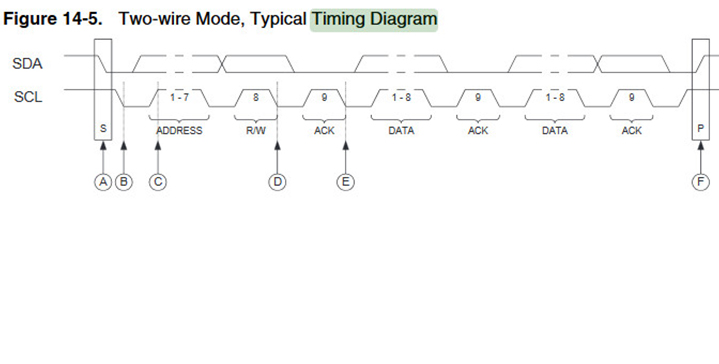
Timing diagrams show how data should be sent to and received from the component, and what speed it should be sent and received.
Programming Hello Board:
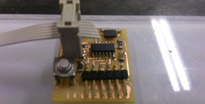
This board contains a button and a LED. In order to program the Hello board, I started to install the softwares and drivers Arduino and ATtiny Board Files.
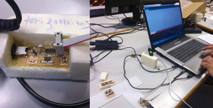
The microcontroller can be programmed with help of the fab ISP board that was made in week 4. The fab ISP board is needed to program the microcontroller of the hello world board. I Connected the fab ISP to the computer with the USB cable, and to the hello world board using the multi colored wire.
My first step was to set the pin of the LED high, which worked. Then I wanted to write a code to include the button. After that I opened the button sample program in the arduino librarys and tested it. I only had to change the controller ports for the led and the button and it went well...
The Code:
In Arduino I went to Files/ Examples/ Basic/ Blink:
/*
Blink
Turns on an LED on for one second, then off for one second, repeatedly.
This example code is in the public domain.
*/
// Pin 13 has an LED connected on most Arduino boards.
// give it a name:
int led = 13;
// the setup routine runs once when you press reset:
void setup() {
// initialize the digital pin as an output.
pinMode(led, OUTPUT);
}
// the loop routine runs over and over again forever:
void loop() {
digitalWrite(led, HIGH); // turn the LED on (HIGH is the voltage level)
delay(500); // wait for a second
digitalWrite(led, LOW); // turn the LED off by making the voltage LOW
delay(500); // wait for a second
}
In Arduino I went to Files/ Examples/ Digital/ Button:
Button
Turns on and off a light emitting diode(LED) connected to digital
pin 13, when pressing a pushbutton attached to pin 2.
The circuit:
* LED attached from pin 13 to ground
* pushbutton attached to pin 2 from +5V
* 10K resistor attached to pin 2 from ground
* Note: on most Arduinos there is already an LED on the board
attached to pin 13.
created 2005
by DojoDave <http://www.0j0.org>
modified 30 Aug 2011
by Tom Igoe
This example code is in the public domain.
http://www.arduino.cc/en/Tutorial/Button
*/
// constants won't change. They're used here to
// set pin numbers:
const int buttonPin = 10; // the number of the pushbutton pin
const int ledPin = 6; // the number of the LED pin
// variables will change:
int buttonState = 0; // variable for reading the pushbutton status
void setup() {
// initialize the LED pin as an output:
pinMode(ledPin, OUTPUT);
// initialize the pushbutton pin as an input:
pinMode(buttonPin, INPUT);
}
void loop(){
// read the state of the pushbutton value:
buttonState = digitalRead(buttonPin);
// check if the pushbutton is pressed.
// if it is, the buttonState is HIGH:
if (buttonState == HIGH) {
// turn LED on:
digitalWrite(ledPin, HIGH);
}
else {
// turn LED off:
digitalWrite(ledPin, LOW);
}
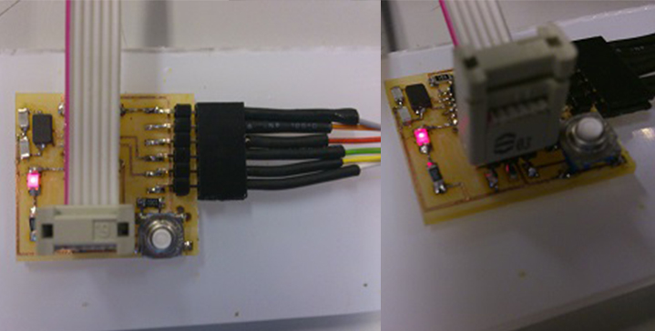
The final result. As I press the button, and the led turns on.