Input Devices (Apr. 13)
Process
Below you will find my dictation, notes and documentation about the processes I went throught with regards to completing the Input Devices exercise. Each of the step and processs will be covered in seperate sections. A link at the bottom of the page will take you to all of the files that I created for this exercise.
Creating the Board
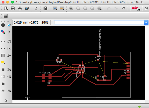
I created a board using the phototransistor, and based it on Neal's hello.light.45 board. I used the hello.light.45 board and the hello.light.45 components to design my own board. I based my designs off of Neal's board, and used Eagle to design it. In the process of designing my board, I learned that you can draw the green wires to connect individual parts to another part or combine multiple parts with out needing to name and than label each connection. I found this to be very useful. After autotracing my path, I made adjustments to it to make it work for me. After creating the design, I cut the board on our Othermill, which I discovered I upload the wrong version of my board due to Eagle having you create a new file each time you go back to make changes to the schematic. Below you can see the image of the connection I forgot compared to the improved schematic and board views:
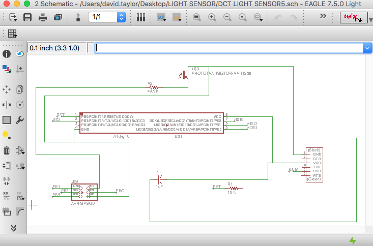
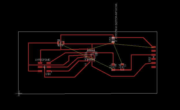
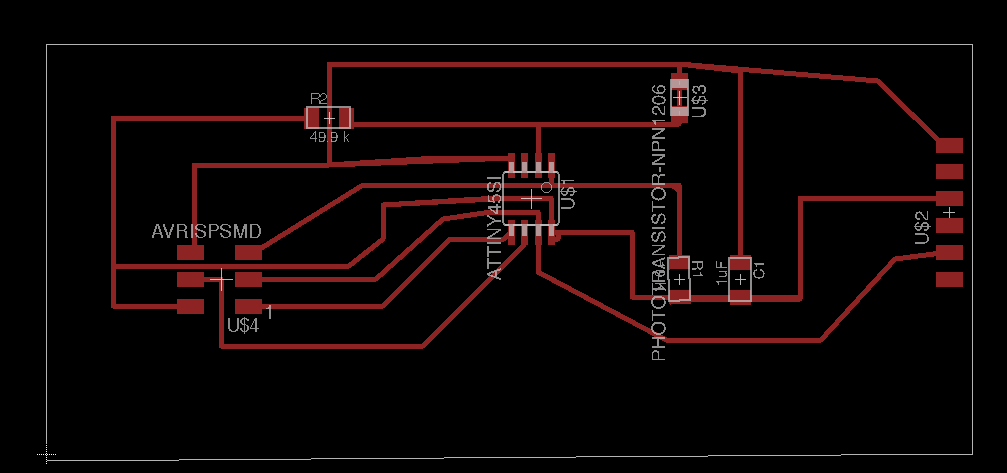
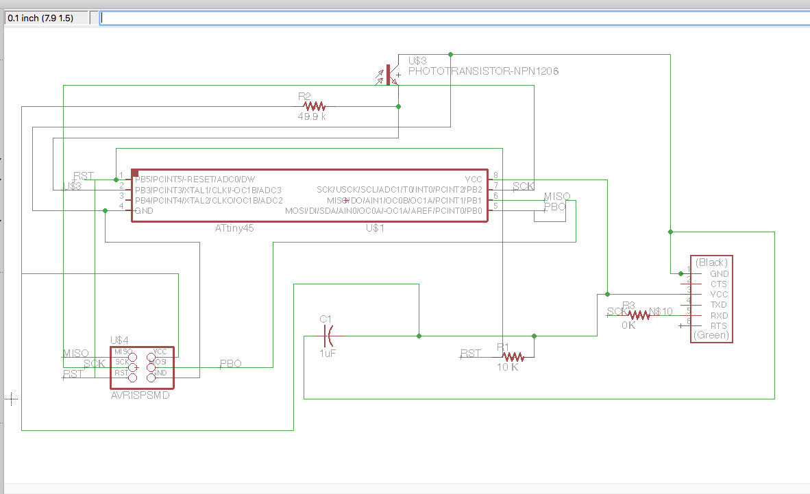
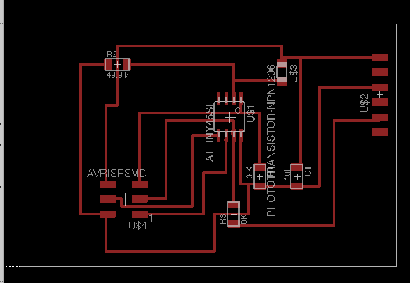
Adam looked over my board and noticed I had my MISO and MOSI pins switched around, so I remade my board in Eagle. Furthermore, I got into a design pickle with my traces using the autotrace feature, and he suggested using a OK resitor as a jumper. This was an extremely helpful idea and process as a whole. He taught me how to use the connection feature in Eagle for making trace connections. Below are my new design:
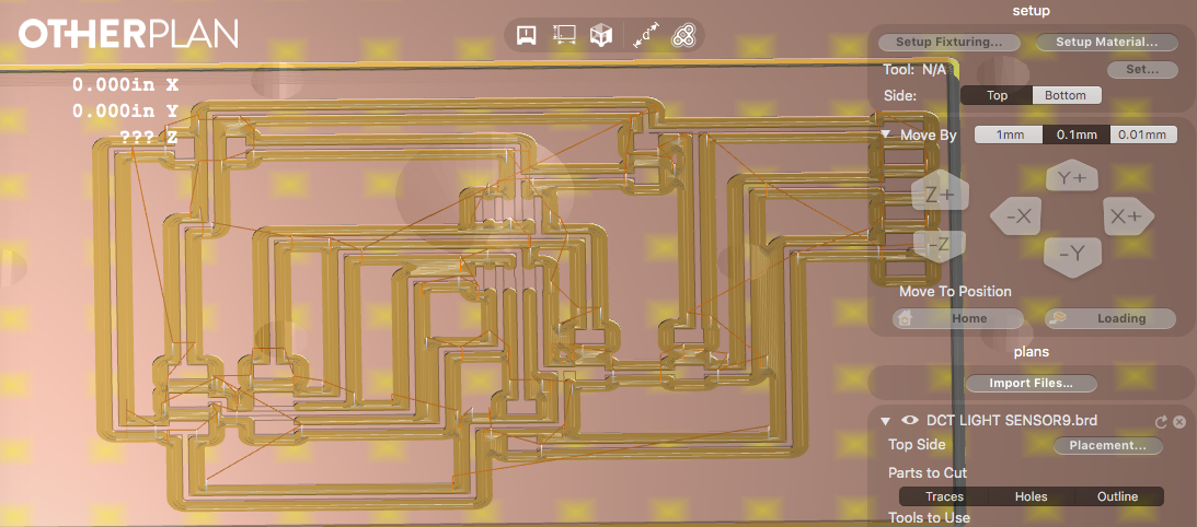
Lastly, when designing my own board, I would open my design in my OtherPlan software on my own computer to see if the traces had enough room when being cut.
Soldering the Board
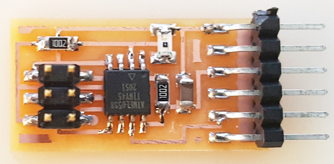
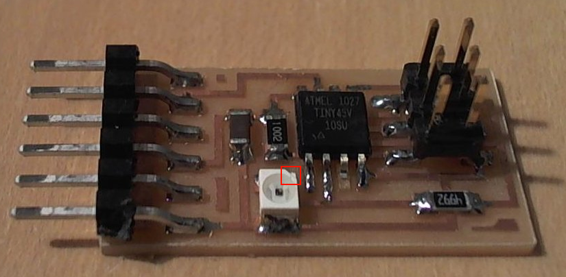
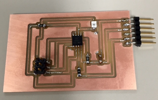
Soldering the board was much faster than I thought it was going to be due to the amount of practice I have had through the other exercises. I soldered each part one at a time as well as I checked over the board to see if there were any issues with traces. Plus, I cleaned the board up using a razor. Soldering each part took about an hour. I learned that the phototransistor has a small notch on one side to identify the positive from the negative side of it. You can see it in the following image:
After soldering each pieces, I had to add a two small jumper wires. One being from the capacitor to the GND trace and the other from the 10K to the VCC on atttiny45. Due to cutting the wrong file. I had a complete my soldering my phototransitor board.
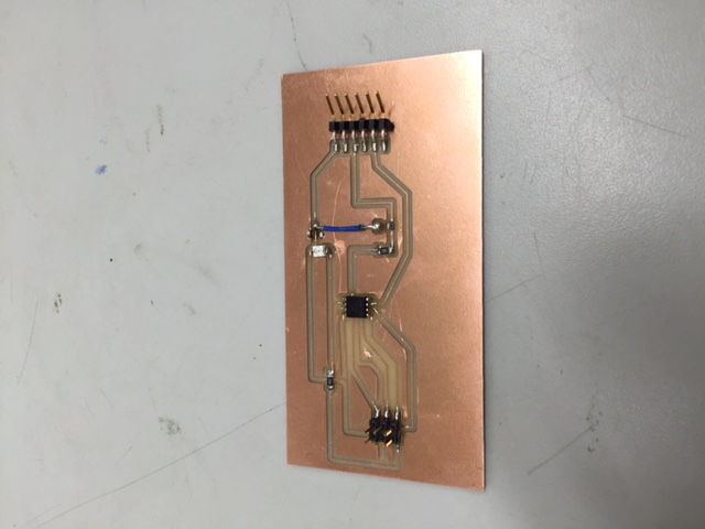
Redesigning my board with the help of Adam, who identified that my MISO and MOSI connections with mixed up, I finally found success. I cut my board, soldered all the peices on to it, which included Attiny45, 1OK, 0K, 49.9K, and 1uf components. After sodlering my board, I connected it to the Averdudess software to check for a connection, which I recieved. Below is my finsihed, successful board:
Coding the Board
I soldered two more boards with no success. I even had Adam look over my boards, which he noticed my design had my MISO AND MOSI were backwards. I than redesigned my board again. The second board I soldered was Neal's phototransistor board, which it still did not work. He could not figure out what was wrong with it. Seperately we both took a multimeter to the traces. We both found that the soldering connections were good to go. So I created another board.
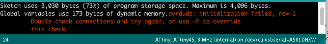
I began the coding process referencing a former Fab Lab Student's site named Edward Loong as well as Jeff Geisinger's site. I referenced this page to begin programming. I did some internet searches too on programming a phototransistor using a Arduino IDE. I did my research using the following sites: Outside Science, Olympia Circuts, and The Robotronics. The sites helped me with developing practice code as well as a starting point. When I began testing code, I began getting the error message below. I using different USB cords, programmers and etc. I even tried using my hello.world board, but I kept getting the same error message, even though my hello.world board has worked over and over. I believe it has something to do with my MacBook Pro. I spoke with Terence about my issue. He told me to try running the hex code that I know works on my hello.world board that has already works too. If it doesn't work using the hex code and hello.world baord, than it is my USB ports on my MacBook Pro. If it does work, than it is my Arduino IDE and it will need to uninstalled and reinstalled as well as with the high-low tech arduino information for using the Attiny44 and Attiny45.
The next thing I did before doing what Terence suggested was to run a sample code on my two boards using a Arduino IDE on a Windows machine. I still got the same erro message. I beginning to wonder if I am not using one of the correct settings in the IDE Tool setup. On my third try, I got my hello.world board working with the Arduino IDE, but not with my phototransitor board. I believe there is something wrong with my board. I changed out the attiny45, but it still didn't work. I am going to make a new board.
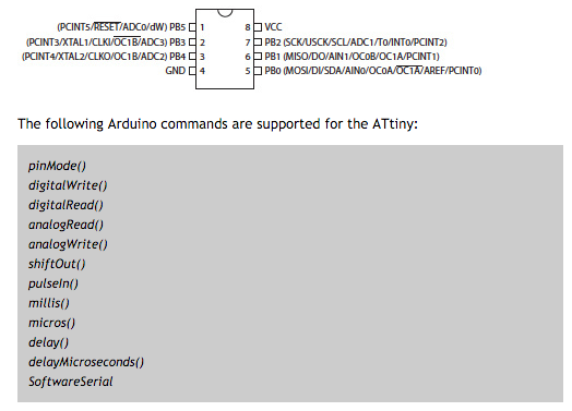
I learned that you need to use the Software Serial library when using the attiny chips. This is the only way you can have your Arduino IDE communication with the serial monitor 9600. By doing this process you are identifying the SoftwareSerial(0,2) that are aligned with the RX and TX. A3 is my analog pin for my code which is the PB3.
In the process of helping Ian, I learned a lot of about using the ultrasonic sensor. I learned how to wire the echo and trigger as well as making sure to have your pins equal the correct analoh connections as well as the correct labeling for the tiny pin names vs. the arduino pin names.
Adam helped me write an if/else statement for my code. It gave me an udnerstanding of the syntax, which I was happy with the fact that I understood how to make it work. My code took a reading of the light and determined if it was greater or less than five, it would write a statement on the serial monitor. He also told me I need to run the Burn Bootloader under Tools when you are using the new chip for the first time with the IDE. Plus, you should use the serial monitor icon in the IDE when opening the serial monitor view, and not the selection under the Tools.Below you can find images and a video:
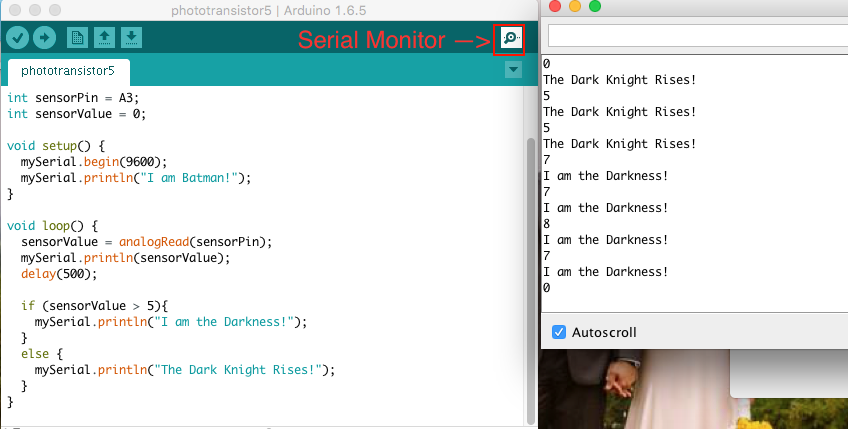
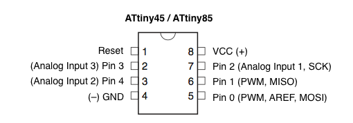
I first ran the code on Richard's photo board that was made by Neal. I than tested it on my own board after it was created. The image below is extremely helpful when coding, because, it gives you the names of the pins and the syntax you can use with the Arduino IDE: