
First time designing boards? thistutorial is a life saver. If you used any CAD based software before you're gonna be fine. Yes, first advantage -probably last one too- of studying architecture.
First, you need to dowload EAGLE from Autodesk's website. There's a free version, you won't need more than that.

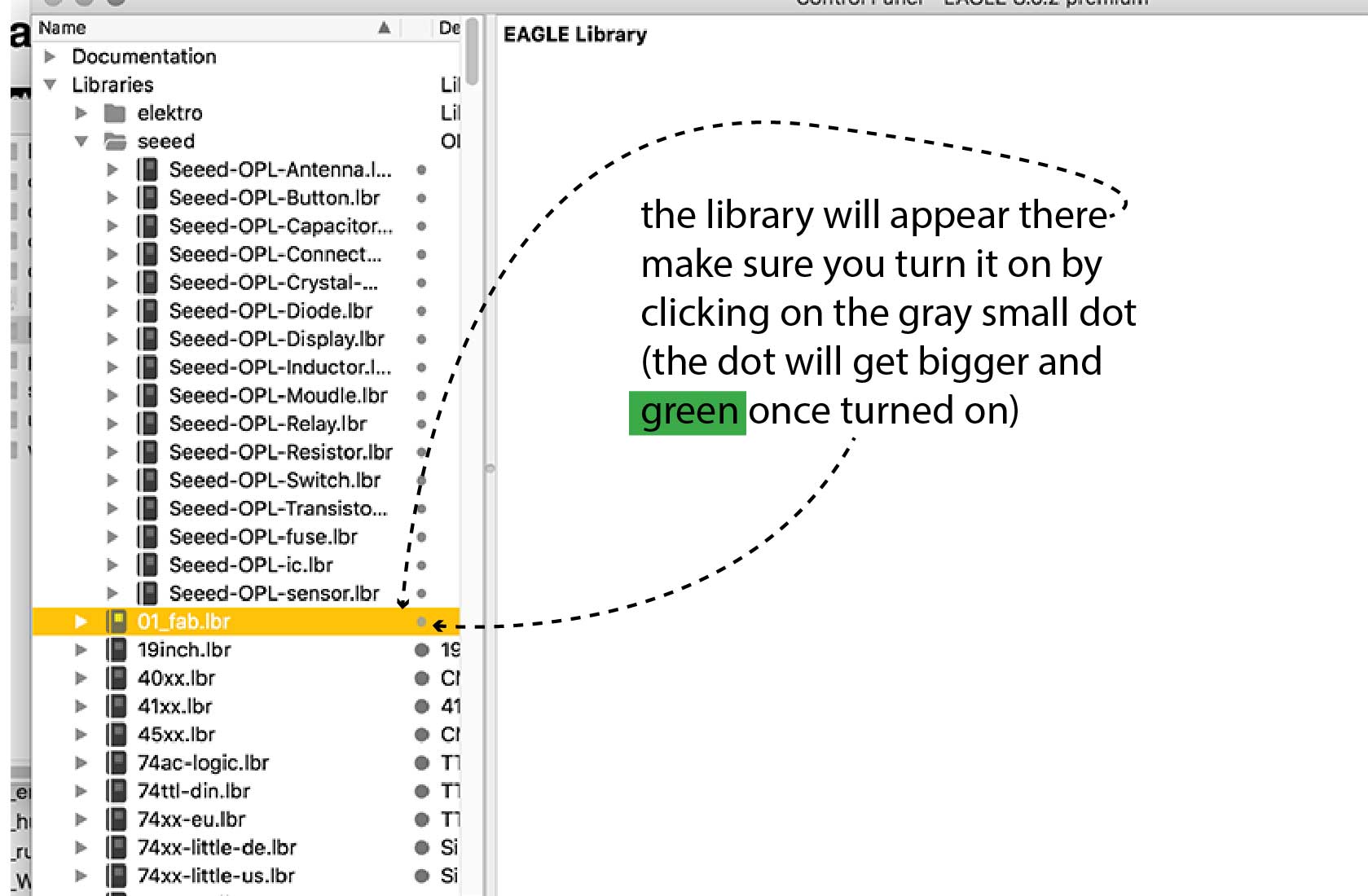
Once this is done FabLab libraries need to be imported to the program (File>Open>Library and import the fablab's library)
The interphase is pretty intuitive, you will basically will type in the command line the command you need (eg:add for adding a component). You can also select the command in the vertical tool bar on the left.

Here's a quick tip for searching components on the ADD panel: you can lookup any component you need by puting his name between **.
The SCHEMATIC is where you pick components and check what you've designed in terms of electricity.
The BOARD is where you adjust what you've created in the Schematic Design and redefine its traces to make it look the way you wnat it to look. Here what you will check will have to do woth design and "posibility" of milling the board (eg: proximity of traces)
Basically you need to add components (type "add" in command line and a window will pop up) to afterwordds make connections.
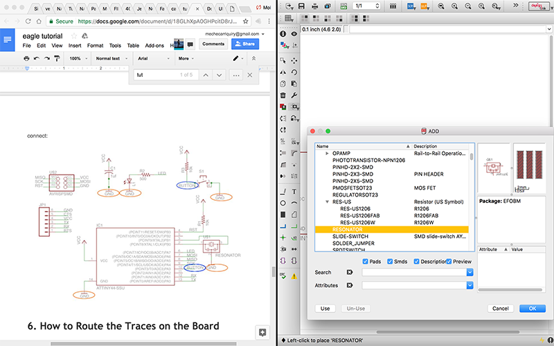
Looking for a resistor? (example) You can look up any component by adding 2 *, one before the word you're looking for, the other after. See printscreen below.
Once your components are added on the screen you will need to make connections using nets (use "net" command on the command line. Once it looks you've connected something to another something you will get a pretty pop up asking if you really want to connect them.
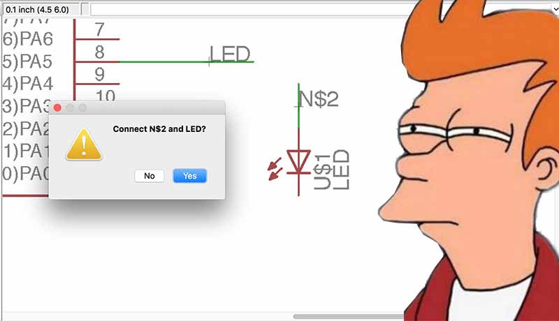
Say yes, you're gonna be ok. Just make sure to connect all components. Once your'e done you can check the Electronic Errors with ERC command.
You need to switch view from schematic (red) to board (green) you will find a small square top left.
First board image is a mess:

components are scattered all arround and not properly layed out. Ergo: you need to draw proper traces (in schematic you use net, here you use traces). /what you need to do is to tell the board how do you want to layout that connection, so yes it's kind of a tiny ant work). Still awesomes designs can be done, you don't need to stick to the ortogonal boring layout seen everywhere.
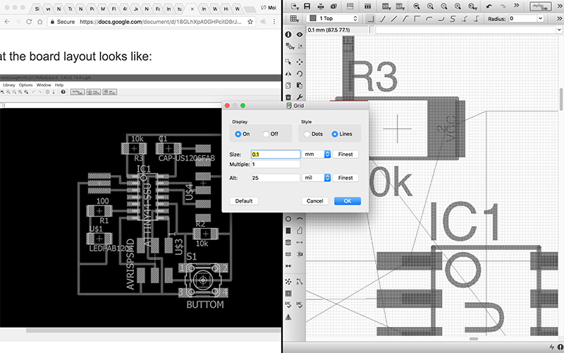
Quick tip on grids. The grid Eagle has by default is in my opinion quite big and restrictive. So if you feel traces are snapping too far away you can diminish the grid parameters typing grid in the command line:
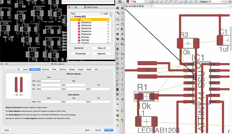
Same way you've got electronics rools you also have DEsign rules. This has nothing to do with electronicts itself but with the milling and board completion. So in this setup you will need to check what's the clearance you need between traces for example.
I used this since our milling machine was locally made @our fablab and we did not used fabmodules. Unlickily cause we could have made more creative traces sending the black and white pattern to be milled. In any case: I Downloaded and installed a generic Gcode creator. Then deployed UPL (see orange icon -center top-

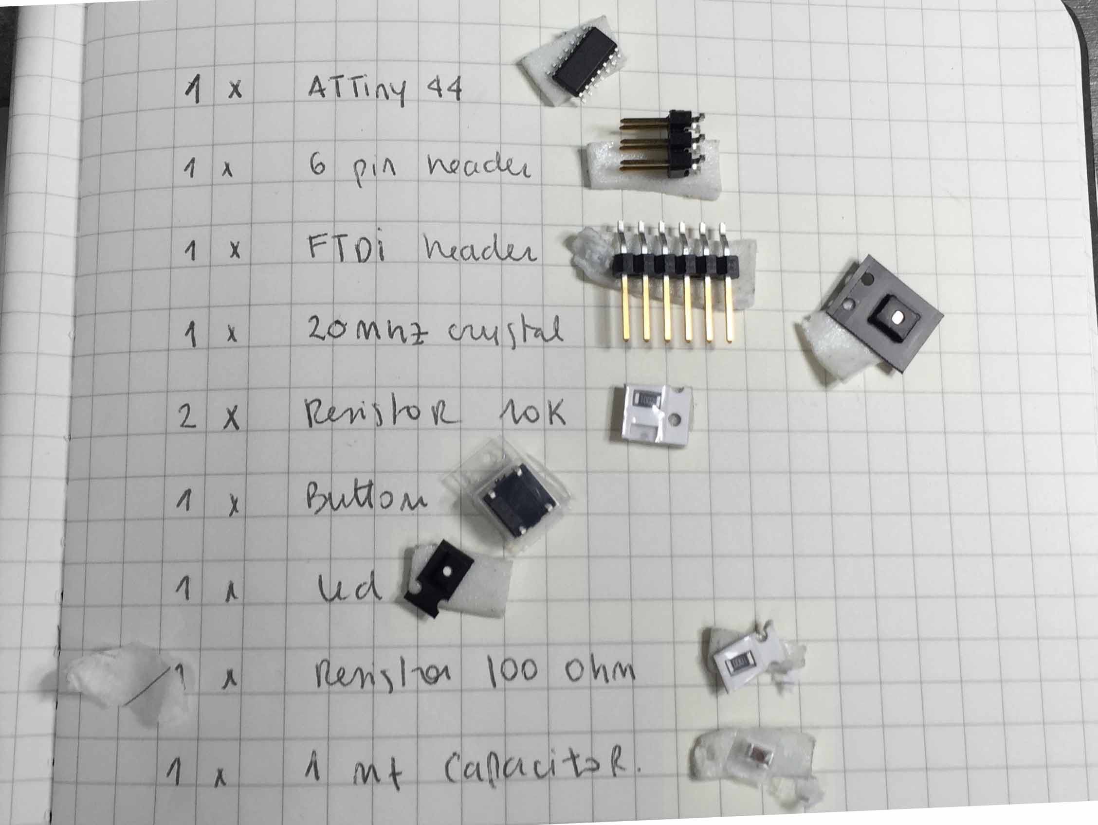
Listing and putting aside components is always the first step:
Below a quick glimpse. You can have a more detailed step-by-step on this in my fourth week. I milled my board using -again- the GAVA-Milling rockstar and sold it -again- using my piano finger power:

Go backto the INDEXor to thefollowing WEEK?