Program the board that was built in Week #6 to do something
I downloaded
and studied (not page by page, obviously) the ATtiny44
datasheet.
This was, actually, a big step in my learning process. If I want to
learn something, I can't just copy what someone else did; so, it was
really important to understand how the ATtiny44 works.
The first test was really
simple: to turn the green led on for a second, then off for another
second, an so on.
To do that, I used Arduino IDE 1.8.1. First, I
had to download the ATTINY44 board, set the clock to 20 MHz and record
the bootloader.
Then, I uploaded the following code:
void setup()
{
pinMode(11, OUTPUT); // ATTINY44 PA2
#define GLED
11
}
void loop()
{
digitalWrite(GLED,
HIGH);
delay(1000);
digitalWrite(GLED,
LOW);
delay(1000);
}
And, to my
satisfaction, it worked! You can see a video below:
Then,
I proceeded to a more elaborate test: once the button is pressed, each
one of the LEDs turns on for a second, in a sequence. This is the code:
int botao
=
0;
voidsetup() {
pinMode(5, OUTPUT); //
ATTINY44 PB2
pinMode(6, OUTPUT); //
ATTINY44 PA7
pinMode(10, INPUT); //
ATTINY44 PA3
pinMode(11, OUTPUT); //
ATTINY44 PA2
#define WLED
5
#define RLED
6
#define
BUTTON 10
#define GLED
11
}
void loop()
{
botao = digitalRead(BUTTON);
if ( BUTTON
== HIGH )
{
digitalWrite(WLED,
HIGH);
delay(1000);
digitalWrite(WLED,
LOW);
delay(1000);
digitalWrite(RLED,
HIGH);
delay(1000);
digitalWrite(RLED,
LOW);
delay(1000);
digitalWrite(GLED,
HIGH);
delay(1000);
digitalWrite(GLED, LOW);
delay(1000);
}
At
first, everything seemed to have worked out, as I had no problems to
upload this new code. But, when I pressed the button, nothing happend. I
changed a few lines in the code and tried again, but this time I
couldn't even upload the file. After Kenzo and I performed a few tests,
we came to the sad conclusion that something, probably the
microcontroller, burned due to a short-circuit triggered by pressing
the button.
As I had fallen behind with other assignments, I
chose to consider this assignment completed, since I would have other
opportunities to design and program these boards.
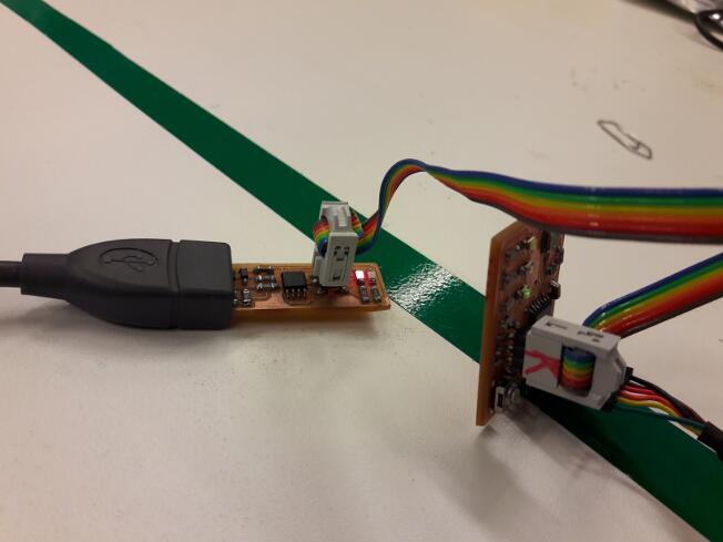
I
must confess that I finished this assignment with lots of doubts. Even
though the programming itself was very clear to me, upon completion of
the task I still could not understand precisely what the hardware I
built did - to be quite honest, I couldn't even understand the need for
two PCBs!
But, as I progressed during the course, specially
while developing my final project, all these doubts were cleared. Not
only I learned the difference between the programmer board and the
programmed board, but I also learned how to communicate with a PC using
a serial port, which was essential for my final project.