Output Devices
Assignment
- Add an output device to a microcontroller board you've designed and program it to do something
What should be done
- Described your design and fabrication process using words/images/screenshots.
- Explained the programming process/es you used and how the microcontroller datasheet helped you.
- Outlined problems and how you fixed them
- Included original design files and code
The Unipolar Stepper
In the final project I wanted to create focus mechanism for the lenses using 5V unipolar stepper driver.


This stepper uses a LN2003A driver which is basically an array of N-type transistors.


I read this PDF for the driver to learn more about how to drive this unipolar stepper and read this PDF for stepper motor basics to learn more about stepper motors in general.
I started by testing this Arduino code mentioned in the PDF
int Pin0 = 1;//blue
int Pin1 = 2;//pink
int Pin2 = 3;//yellow
int Pin3 = 4;//orange
int _step = 0;
boolean dir = true;// gre
void setup()
{
 pinMode(Pin0, OUTPUT);
 pinMode(Pin1, OUTPUT);
 pinMode(Pin2, OUTPUT);
 pinMode(Pin3, OUTPUT);
}
 void loop()
{
 switch(_step){
   case 0:
     digitalWrite(Pin0, LOW);
     digitalWrite(Pin1, LOW);
     digitalWrite(Pin2, LOW);
     digitalWrite(Pin3, HIGH);
   break;
   case 1:
     digitalWrite(Pin0, LOW);
     digitalWrite(Pin1, LOW);
     digitalWrite(Pin2, HIGH);
     digitalWrite(Pin3, HIGH);
   break;
   case 2:
     digitalWrite(Pin0, LOW);
     digitalWrite(Pin1, LOW);
     digitalWrite(Pin2, HIGH);
     digitalWrite(Pin3, LOW);
   break;
   case 3:
     digitalWrite(Pin0, LOW);
     digitalWrite(Pin1, HIGH);
     digitalWrite(Pin2, HIGH);
     digitalWrite(Pin3, LOW);
   break;
   case 4:
     digitalWrite(Pin0, LOW);
     digitalWrite(Pin1, HIGH);
     digitalWrite(Pin2, LOW);
     digitalWrite(Pin3, LOW);
   break;
   case 5:
     digitalWrite(Pin0, HIGH);
     digitalWrite(Pin1, HIGH);
     digitalWrite(Pin2, LOW);
     digitalWrite(Pin3, LOW);
   break;
     case 6:
     digitalWrite(Pin0, HIGH);
     digitalWrite(Pin1, LOW);
     digitalWrite(Pin2, LOW);
     digitalWrite(Pin3, LOW);
   break;
   case 7:
     digitalWrite(Pin0, HIGH);
     digitalWrite(Pin1, LOW);
     digitalWrite(Pin2, LOW);
     digitalWrite(Pin3, HIGH);
   break;
   default:
     digitalWrite(Pin0, LOW);
     digitalWrite(Pin1, LOW);
     digitalWrite(Pin2, LOW);
     digitalWrite(Pin3, LOW);
   break;
 }
 if(dir){
   _step++;
 }else{
   _step--;
 }
 if(_step>7){
   _step=0;
 }
 if(_step<0){
   _step=7;
 }
 delay(1);
}
I ran the code and the changed the int _step = 1;to reverse the direction
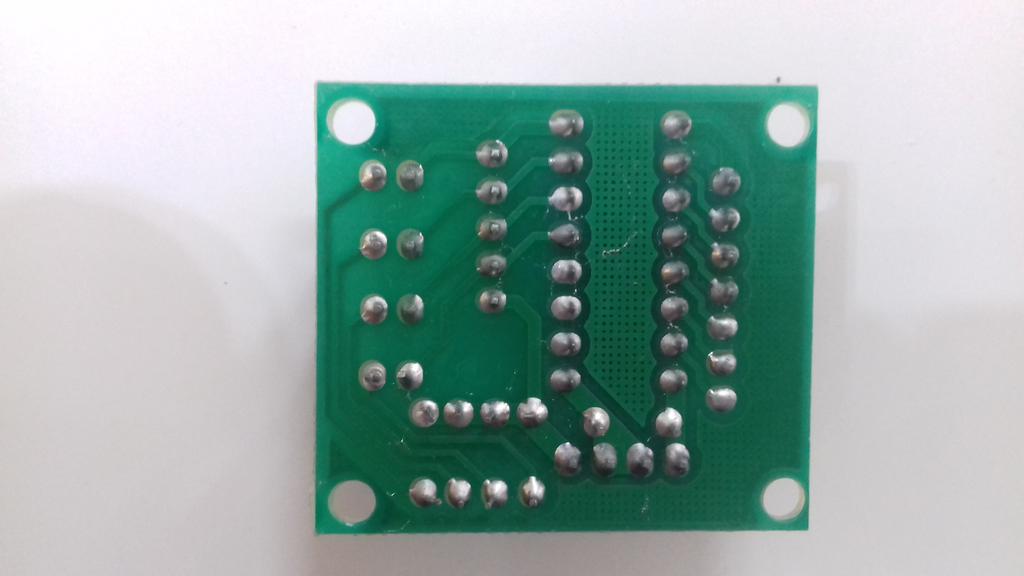
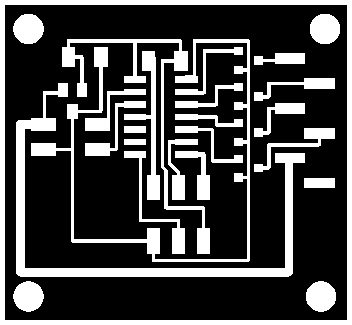
The driver board
The stepper motor driver that I used was basically a Darlington array which is the same as the hello.stepper.44 board. So I redrew that board and removed the voltage regulator as I thought that as the motor is rated 5V which is the same as VCC so I wouldn't need it.


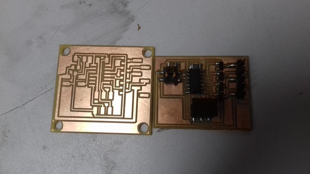
I noticed that a trace is not completely separated probably due to failed DRC check, so I removed the connecting copper using an SMD finishing kit

Then soldered the components.

I used the "hello.stepper.44.half.c" file to test the movement.
//
//
// hello.stepper.44.half.c
//
// half stepping hello-world
//
// Neil Gershenfeld
// 11/14/10
//
// (c) Massachusetts Institute of Technology 2010
// This work may be reproduced, modified, distributed,
// performed, and displayed for any purpose. Copyright is
// retained and must be preserved. The work is provided
// as is; no warranty is provided, and users accept all
// liability.
//

#include <avr/io.h>
#include <util/delay.h>

#define output(directions,pin) (directions |= pin) // set port direction for output
#define set(port,pin) (port |= pin) // set port pin
#define clear(port,pin) (port &= (~pin)) // clear port pin
#define pin_test(pins,pin) (pins & pin) // test for port pin
#define bit_test(byte,bit) (byte & (1 < bit)) // test for bit set

#define MOSFET_port PORTA // MOSFET port
#define MOSFET_direction DDRA // MOSFET direction
#define blue (1 << PA0) // MOSFET output pins
#define pink (1 << PA1) // "
#define yellow (1 << PA2) // "
#define orange (1 << PA3) // "
#define on_delay() _delay_us(50) // PWM on time
#define off_delay() _delay_us(10) // PWM off time
#define PWM_count 100 // number of PWM cycles

static uint8_t count;

//
// blue PWM pulse
//
void pulse_blue() {
   for (count = 0; count < PWM_count; ++count) {
      set(MOSFET_port, blue);
      on_delay();
      clear(MOSFET_port, blue);
      off_delay();
      }
   }
//
// pink PWM pulse
//
void pulse_pink() {
   for (count = 0; count < PWM_count; ++count) {
      set(MOSFET_port, pink);
      on_delay();
      clear(MOSFET_port, pink);
      off_delay();
      }
   }
//
// yellow PWM pulse
//
void pulse_yellow() {
   for (count = 0; count < PWM_count; ++count) {
      set(MOSFET_port, yellow);
      on_delay();
      clear(MOSFET_port, yellow);
      off_delay();
      }
   }
//
// orange PWM pulse
//
void pulse_orange() {
   for (count = 0; count < PWM_count; ++count) {
      set(MOSFET_port, orange);
      on_delay();
      clear(MOSFET_port, orange);
      off_delay();
      }
   }
//
// yellow, orange PWM pulse
//
void pulse_yellow_orange() {
   for (count = 0; count < PWM_count; ++count) {
      set(MOSFET_port, yellow);
      set(MOSFET_port, orange);
      on_delay();
      clear(MOSFET_port, yellow);
      clear(MOSFET_port, orange);
      off_delay();
      }
   }
//
// yellow, pink PWM pulse
//
void pulse_yellow_pink() {
   for (count = 0; count < PWM_count; ++count) {
      set(MOSFET_port, yellow);
      set(MOSFET_port, pink);
      on_delay();
      clear(MOSFET_port, yellow);
      clear(MOSFET_port, pink);
      off_delay();
      }
   }
//
// orange, blue PWM pulse
//
void pulse_orange_blue() {
   for (count = 0; count < PWM_count; ++count) {
      set(MOSFET_port, orange);
      set(MOSFET_port, blue);
      on_delay();
      clear(MOSFET_port, orange);
      clear(MOSFET_port, blue);
      off_delay();
      }
   }
//
// orange, pink PWM pulse
//
void pulse_orange_pink() {
   for (count = 0; count < PWM_count; ++count) {
      set(MOSFET_port, orange);
      set(MOSFET_port, pink);
      on_delay();
      clear(MOSFET_port, orange);
      clear(MOSFET_port, pink);
      off_delay();
      }
   }
//
// clockwise step
//
void step_cw() {
   pulse_yellow_blue();
   pulse_yellow();
   pulse_yellow_pink();
   pulse_pink();
   pulse_orange_pink();
   pulse_orange();
   pulse_orange_blue();
   pulse_blue();
   }
//
// counter-clockwise step
//
void step_ccw() {
   pulse_blue();
   pulse_orange_blue();
   pulse_orange();
   pulse_orange_pink();
   pulse_pink();
   pulse_yellow_pink();
   pulse_yellow();
   pulse_yellow_blue();
   }

int main(void) {
   //
   // main
   //
   static uint8_t i,j;
   //
   // set clock divider to /1
   //
   CLKPR = (1 << CLKPCE);
   CLKPR = (0 << CLKPS3) | (0 << CLKPS2) | (0 << CLKPS1) | (0 << CLKPS0);
   //
   // initialize MOSFET pins
   //
   clear(MOSFET_port, blue);
   output(MOSFET_direction, blue);
   clear(MOSFET_port, pink);
   output(MOSFET_direction, pink);
   clear(MOSFET_port, yellow);
   output(MOSFET_direction, yellow);
   clear(MOSFET_port, orange);
   output(MOSFET_direction, orange);
   //
   // main loop
   //
   while (1) {
      // for (i = 0; i < 10; ++i) {
      //    for (j = 0; j < i; ++j)
      //       step_cw();
      //    for (j = 0; j < i; ++j)
      //       step_ccw();
      //    }
      // for (i = 10; i > 0; --i) {
      //    for (j = 0; j < i; ++j)
      //       step_cw();
      //    for (j = 0; j < i; ++j)
      //       step_ccw();
      //    }
      step_cw();
      }
   }
Serial Communication
To be able to control the stepper from a computer or another MCU, I wanted to programm it to handle RS-232 signals. I also wanted to make mounting point for it to be placed beside the stepper if needed.

I created a C file to receive the number of steps serially and actuate the motor accordingly. Positive values will move the stepper clockwise and negative values will move it counter-clockwise. The MCU will send a flag indicator to announce the movement of the motor.
#include <avr/io.h>
#include <util/delay.h>
#include <avr/pgmspace.h>
#include <string.h>

#define output(directions,pin) (directions |= pin) // set port direction for output
#define input(directions,pin) (directions &= (~pin)) // set port direction for input
#define set(port,pin) (port |= pin) // set port pin
#define clear(port,pin) (port &= (~pin)) // clear port pin
#define pin_test(pins,pin) (pins & pin) // test for port pin
#define bit_test(byte,bit) (byte & (1 << bit)) // test for bit set
#define bit_delay_time 102 // bit delay for 9600 with overhead
#define bit_delay() _delay_us(bit_delay_time) // RS232 bit delay
#define half_bit_delay() _delay_us(bit_delay_time/2) // RS232 half bit delay

#define MOSFET_port PORTA // MOSFET port
#define MOSFET_direction DDRA // MOSFET direction
#define blue (1 << PA0) // MOSFET output pins
#define pink (1 << PA1) // "
#define yellow (1 << PA2) // "
#define orange (1 << PA3) // "
#define on_delay() _delay_us(50) // PWM on time
#define off_delay() _delay_us(10) // PWM off time
#define PWM_count 100 // number of PWM cycles

#define serial_port PORTB
#define serial_direction DDRB
#define serial_pins PINB
#define serial_pin_in (1 << PB0)
#define serial_pin_out (1 << PB1)

#define working '1'
#define idle '0'

void get_char(volatile unsigned char *pins, unsigned char pin, char *rxbyte) {
   //
   // read character into rxbyte on pins pin
   //    assumes line driver (inverts bits)
   //
   *rxbyte = 0;
   while (pin_test(*pins,pin))
      //
      // wait for start bit
      //
      ;
   //
   // delay to middle of first data bit
   //
   half_bit_delay();
   bit_delay();
   //
   // unrolled loop to read data bits
   //
   if pin_test(*pins,pin)
      *rxbyte |= (1 << 0);
   else
      *rxbyte |= (0 << 0);
   bit_delay();
   if pin_test(*pins,pin)
      *rxbyte |= (1 << 1);
   else
      *rxbyte |= (0 << 1);
   bit_delay();
   if pin_test(*pins,pin)
      *rxbyte |= (1 << 2);
   else
      *rxbyte |= (0 << 2);
   bit_delay();
   if pin_test(*pins,pin)
      *rxbyte |= (1 << 3);
   else
      *rxbyte |= (0 << 3);
   bit_delay();
   if pin_test(*pins,pin)
      *rxbyte |= (1 << 4);
   else
      *rxbyte |= (0 << 4);
   bit_delay();
   if pin_test(*pins,pin)
      *rxbyte |= (1 << 5);
   else
      *rxbyte |= (0 << 5);
   bit_delay();
   if pin_test(*pins,pin)
      *rxbyte |= (1 << 6);
   else
      *rxbyte |= (0 << 6);
   bit_delay();
   if pin_test(*pins,pin)
      *rxbyte |= (1 << 7);
   else
      *rxbyte |= (0 << 7);
   //
   // wait for stop bit
   //
   bit_delay();
   half_bit_delay();
   }

void put_char(volatile unsigned char *port, unsigned char pin, char txchar) {
   //
   // send character in txchar on port pin
   //    assumes line driver (inverts bits)
   //
   // start bit
   //
   clear(*port,pin);
   bit_delay();
   //
   // unrolled loop to write data bits
   //
   if bit_test(txchar,0)
      set(*port,pin);
   else
      clear(*port,pin);
   bit_delay();
   if bit_test(txchar,1)
      set(*port,pin);
   else
      clear(*port,pin);
   bit_delay();
   if bit_test(txchar,2)
      set(*port,pin);
   else
      clear(*port,pin);
   bit_delay();
   if bit_test(txchar,3)
      set(*port,pin);
   else
      clear(*port,pin);
   bit_delay();
   if bit_test(txchar,4)
      set(*port,pin);
   else
      clear(*port,pin);
   bit_delay();
   if bit_test(txchar,5)
      set(*port,pin);
   else
      clear(*port,pin);
   bit_delay();
   if bit_test(txchar,6)
      set(*port,pin);
   else
      clear(*port,pin);
   bit_delay();
   if bit_test(txchar,7)
      set(*port,pin);
   else
      clear(*port,pin);
   bit_delay();
   //
   // stop bit
   //
   set(*port,pin);
   bit_delay();
   //
   // char delay
   //
   bit_delay();
   }

void put_string(volatile unsigned char *port, unsigned char pin, PGM_P str) {
   //
   // send character in txchar on port pin
   //    assumes line driver (inverts bits)
   //
   static char chr;
   static int index;
   index = 0;
   do {
      chr = pgm_read_byte(&(str[index]));
      put_char(&serial_port, serial_pin_out, chr);
      ++index;
      } while (chr != 0);
   }
void step(dir,steps){
   static int step;
   static int count;
   step = 0;
   dir=1;
   count=0;
   if(steps<0){
	steps*=-1;
	dir=0;
  }
put_char(&serial_port, serial_pin_out, working);
   while (count<steps*8) {
        switch(step){
         case 0:
            clear(MOSFET_port,blue);
            clear(MOSFET_port,pink);
            clear(MOSFET_port,yellow);
            set(MOSFET_port,orange);
         break;
         case 1:
            clear(MOSFET_port,blue);
            clear(MOSFET_port,pink);
            set(MOSFET_port,yellow);
            set(MOSFET_port,orange);
         break;
         case 2:
            clear(MOSFET_port,blue);
            clear(MOSFET_port,pink);
            set(MOSFET_port,yellow);
            clear(MOSFET_port,orange);
         break;
         case 3:
            clear(MOSFET_port,blue);
            set(MOSFET_port,pink);
            set(MOSFET_port,yellow);
            clear(MOSFET_port,orange);
         break;
         case 4:
            clear(MOSFET_port,blue);
            set(MOSFET_port,pink);
            clear(MOSFET_port,yellow);
            clear(MOSFET_port,orange);
         break;
         case 5:
            set(MOSFET_port,blue);
            set(MOSFET_port,pink);
            clear(MOSFET_port,yellow);
            clear(MOSFET_port,orange);
         break;
         case 6:
            set(MOSFET_port,blue);
            clear(MOSFET_port,pink);
            clear(MOSFET_port,yellow);
            clear(MOSFET_port,orange);
         break;
         case 7:
            set(MOSFET_port,blue);
            clear(MOSFET_port,pink);
            clear(MOSFET_port,yellow);
            set(MOSFET_port,orange);
         break;
         default:
            clear(MOSFET_port,blue);
            clear(MOSFET_port,pink);
            clear(MOSFET_port,yellow);
            clear(MOSFET_port,orange);
         break;
        }
        if (dir == 1)
        {
         step++;
        }else{
         step--;
        }

        if(step>7){
         step=0;
        }
        if(step<0){
         step=7;
        }
	count++;
        _delay_ms(1);
     }
put_char(&serial_port, serial_pin_out, idle);
}
int main(void) {
	//
	// main
	//

	static char chr;

	//
	// set clock divider to /1
	//
	CLKPR = (1 << CLKPCE);
	CLKPR = (0 << CLKPS3) | (0 << CLKPS2) | (0 << CLKPS1) | (0 << CLKPS0);
	//
	// initialize MOSFET pins
	//
	clear(MOSFET_port, blue);
	output(MOSFET_direction, blue);
	clear(MOSFET_port, pink);
	output(MOSFET_direction, pink);
	clear(MOSFET_port, yellow);
	output(MOSFET_direction, yellow);
	clear(MOSFET_port, orange);
	output(MOSFET_direction, orange);
	//
	// initialize output pins
	//
	set(serial_port, serial_pin_out);
	output(serial_direction, serial_pin_out);
	//
	// main loop
	//
	put_char(&serial_port, serial_pin_out, idle);

	while (1) {

		get_char(&serial_pins, serial_pin_in, &chr);


		if(chr){
		step(1,chr);
		}

	  }
	}