Week 8
Embedded Programming

The goal of this week was to read the microcontroller(MCU) data sheet, understand the ability we have to manipulate the MCU at hardware level, and program our board to do something
Reading Datasheet
This section covers the different datasheets read. I chose to have a wide coverage of datasheets as my final project is heavily electronics based. I chose to go into different architectures as well to understand them better. However, all these are MicroControllers - they don't have the power to load Operating Systems (Android/Linux etc) on them, they allow themselves to be programmed and will execute the program well. They tend to draw significantly lesser power and in cases of pure operation, might prove to be faster than Microprocessors per clock.
- ATTINY 44
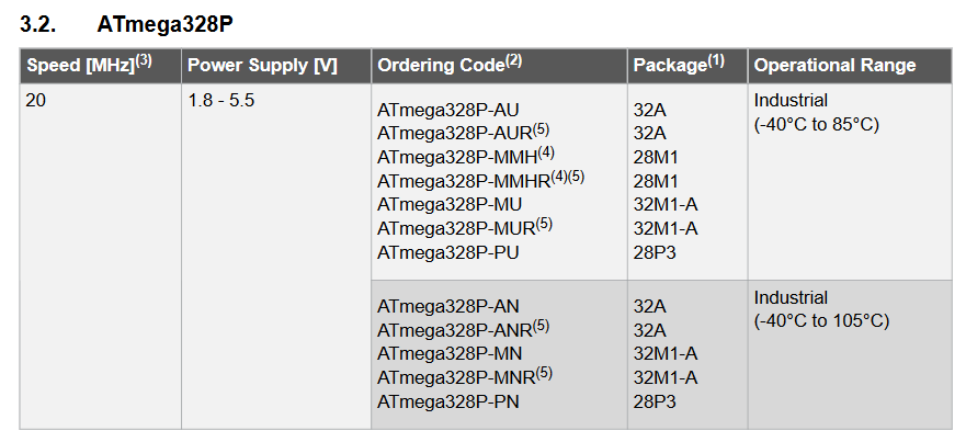
- ATMega 328
- STMicro 32F
Learnings
- Reading the datasheet without a good grasp over electronics/chip design or a plan is dangerous to motivation and mental health.(WINK WINK) click here to read a great tutorial on how to speed-read a datasheet.
- Things to read in the document in sequence of importance: Features talks about the overview of the chip, giving an idea of what can be done. Focus on Peripherals, I/O, Operating Voltage and Memory to understand the limitations.Pin Configuration enables you to understand how the 14 pins on the ATTINY44 is laid out and hwat functions each pin can perform. Power Mode and sleep configuration and Electrical characteristics
- Each chip - however small, is COMPLEX. It has multiple components interacting within the object
- Time - timing of each function is extremely critical - it can lead to corruption or even data loss.
- Types of Memory - while I knew the concepts of EEPROM and Non Volatile Memory (NVM), I clearly understood how they work and the impact of clocks on them. For ex, Reading EEPROM halts instructions for 4 cycles etc
Dictionary
Some basic terminology we need to understand to help understand the datasheet better
- Clock - typically refers to the frequency at which a chip like a central processing unit (CPU), one core of a multi-core processor, is running and is used as an indicator of the processor's speed.
- Operand - an input for an operation
- Processor Register - is a quickly accessible location available to a computer's central processing unit (CPU). Registers usually consist of a small amount of fast storage, although some registers have specific hardware functions, and may be read-only or write-only.
- Pipeline - pipeline is a set of data processing elements connected in series, where the output of one element is the input of the next one. The elements of a pipeline are often executed in parallel or in time-sliced fashion; in that case, some amount of buffer storage is often inserted between elements.
Pin Outs
THe most useful page I saw in the data sheet was the pin configuration. Since we work extensively with ATTiny 44, 45 and Atmega 328P, and I personally with an ESP8266-12E Microcontroller+WiFi Module here are some pinouts I refer to regularly.
Atmega 328P


Attiny 44

Attiny 45

ESP8266 12E

Programming the Board
I tried installing the Atmel Suite, but it is HUGE and BULKY to install, the installer being about 700 mb and installation taking 15-20 minutes+ to complete. Hence I have dropped it.
Softwares considered
Arduino IDESetting up Arduino IDE - Attiny
Arduino IDE can program the Attiny family, but needs the board definition to be added. To do this, press
Cntrl+Comma
add the below text into the box saying "Additional Boards Manager URLs" as shown in the image below
https://raw.githubusercontent.com/damellis/attiny/ide-1.6.x-boards-manager/package_damellis_attiny_index.json
 While you are there, also select the option to enable line numbers. Then go to the Menu item Tools and select Board Manager
  Then this window opens up
  Scroll to the end and click on "Attiny" to see the install button. Click to install. I have already installed it, hence you see a "remove" button in my case

Now that the board definitions are installed, you can get to setting up the Uno to act as your ISP. I chose this route after the drivers for FabISP on Windows10 got corrupted during an upgrade. Arduino IDE provides a code to enable the Arduino to act as an ISP. Its called Arduino as ISP and is found as shown in the image below  In the code, scroll down to line 81, you should see a "//" commenting out that line like this
  Change that by deleting the "//" like this
  Make sure that the settings to upload the code are like this
 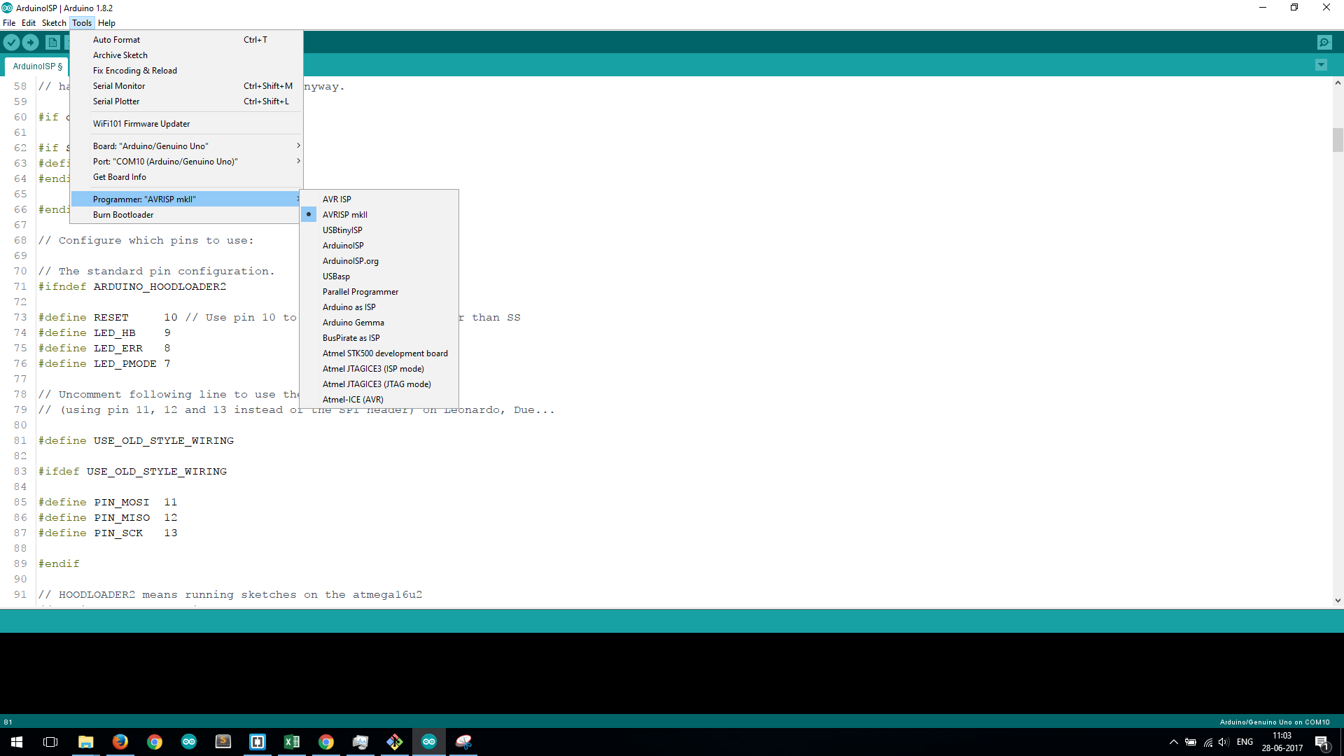 Upon successful upload, you should see this
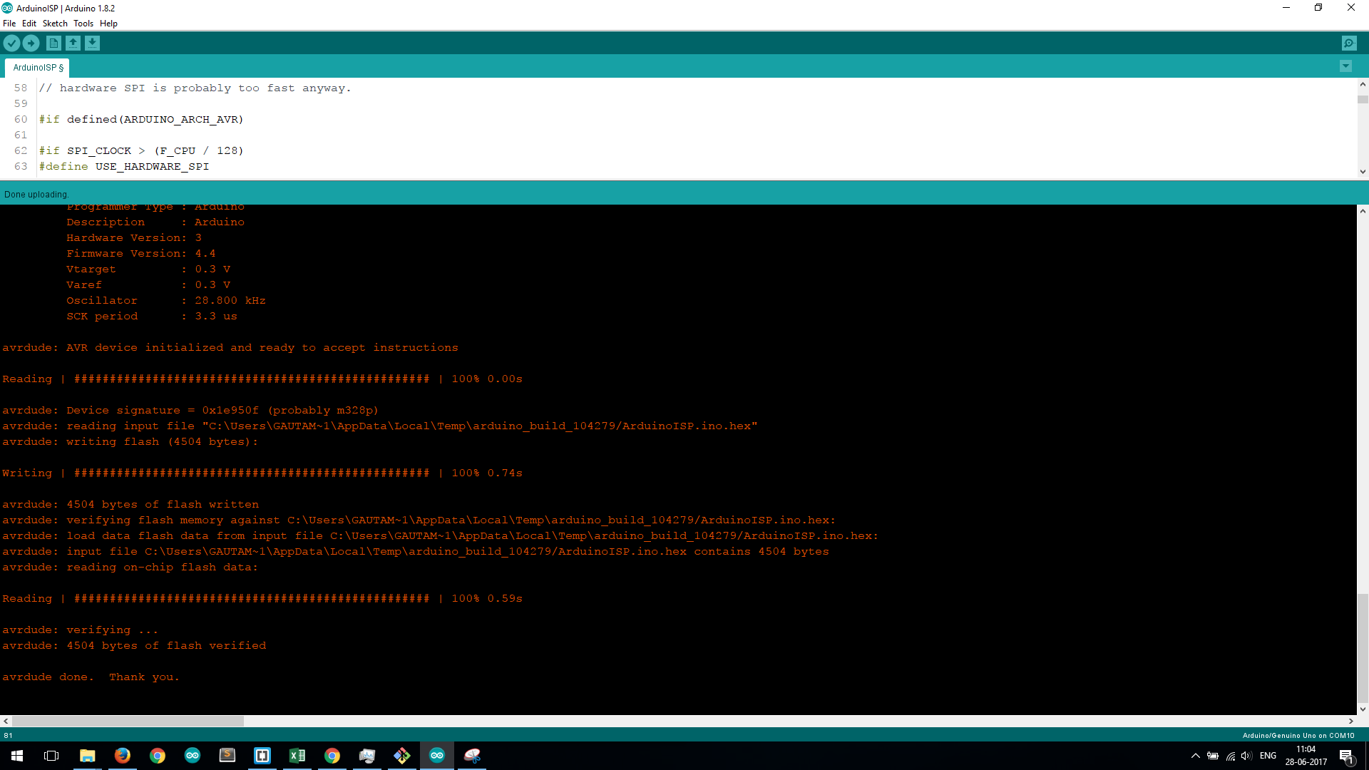
Experiments with Coding
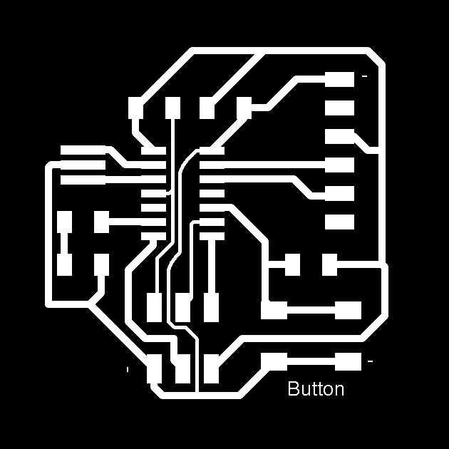
UpdateAs an initial experiment, I made a board which was a redesign of the Hello Echo Board, with a button and simple LED. This video shows its working.
week6 from Gautam Prakash on Vimeo.
LED Blink
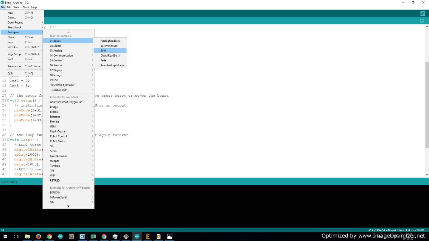
I used the Blink code to make my LEDs blink - the pins were connected to pins 10, 9, 8, making RGB blinking easy. I defined the 3 led pins as variables and called them as needed. Attached is the code I used. Modifying the code to make multiple LEDs turn on and off before calling a delay will give combinations of colours. 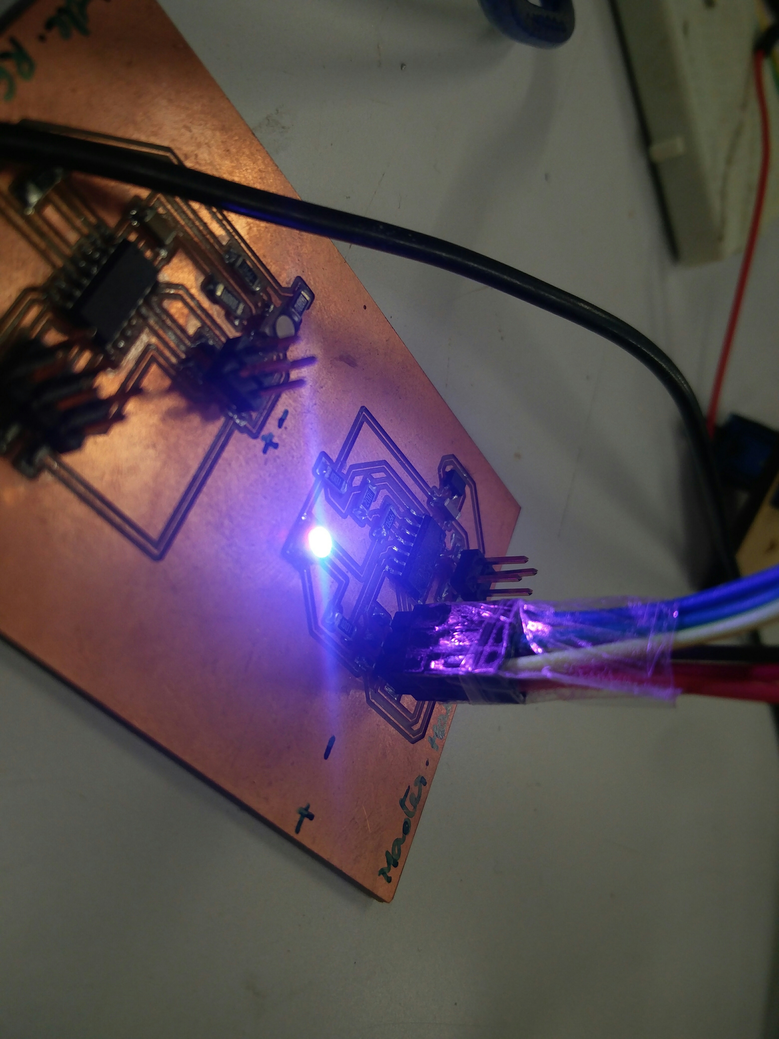
Button to change colour of blink
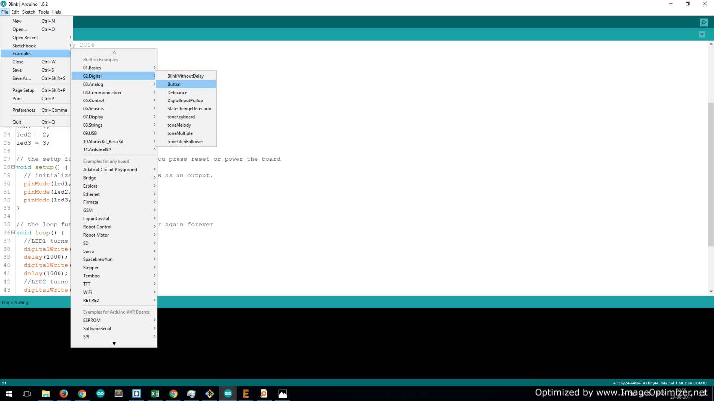
As shown above, I accessed the example button code. TO make it fun, I redefined all 3 LED legs (R,G,B) as variables and called them all together when the button was pressed. The button was connected to pin 0.