Week 15
Networking and Communication

The Design
For my final project, I needed a baord capable of being manufactured easily, capable of taking input from various sensors and controlling different ourput devices. Thus was born the PinToo Board. It was decided early on to use Wifi as my networking methodoogy. Every one in India has a smart phone, with internet, so putting wifi as the mode of network was based on this fact. ESP8266-12E has proved to be mature, ironing out the issues of the Esp8266-1 and 03. It is used in the NodeMCU development board, which we tested for 5 months now. The concept was tested on the NodeMCU and WeMos D1 for a long duration (Febraury, where the system was sending water flow data online to a private thingspeak server created from thier Github code on an instance of Digital Ocean.
HTTP-REST vs MQTT
This was tested out as well. HTTP-REST allows for ease of use, as it requires 0 network configration, or modification of firewall settings. MQTT required some firewall settings. However, it is extremely effieicent on the data transmission side, accounting for about 40-60% lesser traffic than a HTTP-REST protocal. It also allows for data encryption. I ahve decided to keep both options open, but will use MQTT in the final project.
Fabrication
The StashaKit was taken from Jakob Nilson's Github account and edited with Eagle. 3 versions of the board were made and milled on the Modela

- V1 : Was done on a waste board, with a LM1117 3.3V smt Voltage regulator connected from VCC to reduce power to the VCC and CH pins on the ESP. The RXTX lines were left to be 5v. 2 jumper pins were given, so that the ESP could be tested independently, with an FTDI chip. This edition had one issue - the ESP8266 ran on Baud of 115200 by default, curropting the readings on the Serial Monitor when run through the Atmega 328P.

- V2 : SHifted back to a SMT LM1117 3.3v voltage regulator and tracks for the ESP's RX-TX were put on to A4 and A3 by mistake. This edition was considered a fail.

- V3 : We decided to use a LD33-CV DIP voltage regulator, as it handled heat better. RX and TX was decided to be kept seperate, so that there would be no issues with loosing digital pins if needed, and gave the flexibilty to use anddigital pins of our choice.

Issues and Fixes
 Baud Rate Issue- The ESP8266-12E by default runs on baud rate 115200. This means it communicates very fast by default. The Atmega 328P, which is the Microcontroller struggles to communicate at this speed. To test, I used this code to communicate between the Atmega and ESP. It allowed me to see that issue. I then asked on India Telegram Group, and got a tip from Yadu Sharon that it could be an baud rate issue. Using the same code, I sent this command to the ESP to set baud rate to 9600 by default. This is the speed Atmega 328P communicates in default by.
AT+CIOBAUD=9600
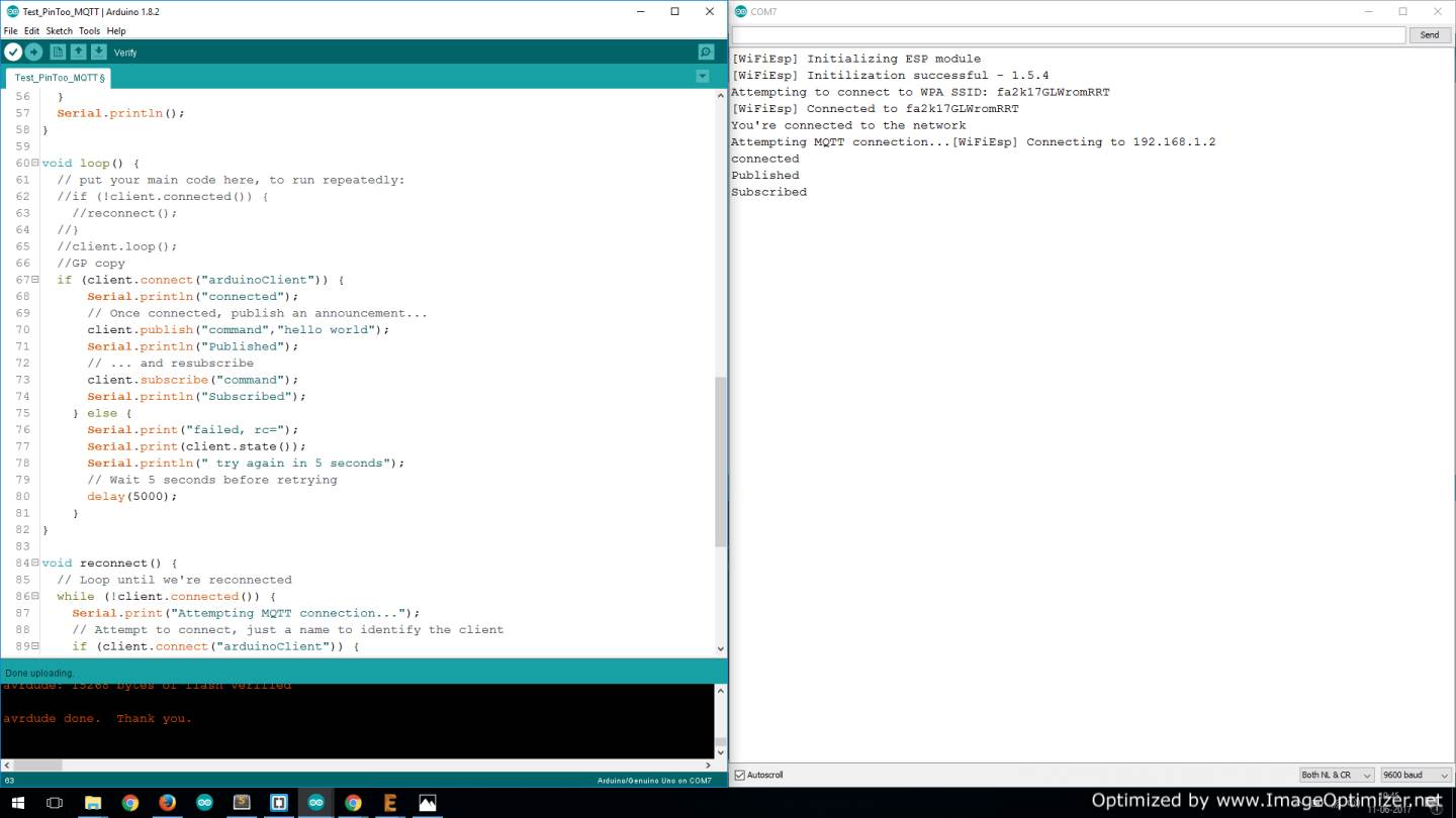
Post this, I was able to communicate without issues and get this output

- Faulty power regulator A friend, Mohit helped diagnose backwards from the ESP this Issue after I showed him the voltage fluctuation at the 5V pin outs I had left. The LM1117 was defective, supplying a stable 3.2v to the ESP, but fluctuating the Atmega's power between 4.8-5v preiodically, causing it to reset.

- Delay is needed between messages for a Raspberry Pi server. I managed to crash the server, as the messsages from PinToo went very fast. Adding a delay of 1 second fixed the issue of non-respponsive baord. The learning was to make the delay between messages for certain sensors like distance about 3-5 seconds and flow sensors to about 1 second.
Assignment
Using this code based on a tutorial by Sony Arohe, I got the PinToo board to send a test message on to my Server. Changes made to make this possible in the setup I had were:IPAddress server(192, 168, 1, 3);
Entered the IP address of my Raspberry Pi 3 on which I had installed Mosquitto service.
char ssid[] = "WiFi SSID Name here"; // your network SSID (name) char pass[] = "WiFi Password here";SoftwareSerial soft(11,12); // RX, TX
The digital pins I have connected the ESP's RX-TX to.- To ensure I am getting data, I installed 2 softwares for now. One is google Chrome based called MQTT Lens
PinToo board v3 uploading data via mqtt from Gautam Prakash on Vimeo.
PinToo board v3 uploading data via mqtt from Gautam Prakash on Vimeo.

Week 15: Networking: Backend testing of MQTT from Gautam Prakash on Vimeo.
Conclusion
I have added a ESP8266-12E module to a board based loosely on the SatshaKit Design, called Pin4. This board connects to the internet via WiFi and transmits sensor data via MQTT protocol as shown in the video.