Week 2
Computer Aided Design
ASSIGNMENT
Model (draw, render, animate, simulate, …) a possible final project,
and post it on your class page with original 2D and 3D files.
Final Project
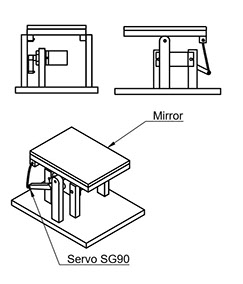
I Started Designing The Segment Element For My Final Project As Follows
First I Imported and .STL File of SG90 Servo for Dimensions
What you see is the Early stage Visualization of my Final Project Single Element of The Segment Display System.
Servo Dimensions Reference- Right Way to do it
This Weeks Asignment Was Focusend on Exploreing 3D Modeling Software
Have been Experienced in Modeling for Animation and Visual Effects, Paramatric and Precision modeling is a complitly new exprerince for me.
My Favourate Modeling Tool is Autodesk 3ds Max.
Considering We have to Learn and explore new software I Chose Fusion 360.
My reason to choose Fusion 360 is, the interface is minimal As only the relevant options gets enabled this heps us focus on our Designing
I stared learning Fusion 360 few days before FAB Academy.
And its easy to get started with Fusion 360.
Getting Fusion
For Students (Practically any one) software is free to use for 1 year.
Create A Auto desk ID to get started.
Just Download the Software
Check out these Tutorials to get started Fusion 360.
Note: Fusion 360 Needs Internet Access at Regular Interval to update itself. As Software Get updated quite offend
Fusion 360


.jpg?crc=4043448033)
.jpg?crc=213540348)
.jpg?crc=252360253)
.jpg?crc=519910855)
.jpg?crc=3925946036)
.jpg?crc=4170754982)
442x249.jpg?crc=4127249917)
442x249.jpg?crc=3794013357)
442x249.jpg?crc=4188467214)
451x206.jpg?crc=65952605)
442x249.jpg?crc=237488630)
442x249.jpg?crc=81773896)
The link to the STL file is attached
This way its easy to get dimensions
instead of manually feeding all the values
GET FILE
To enter parameters or say global variables that can be used through out your design.
Goto: Modify > Change Parameters.
This Way Once we update the Parameter's Value , The 3d model Gets Updates Respectively.
I also gave a basic texture to explore how it works.
Fusion downloads the texture as and when needed form Internet.
Note in << this image we are using the saved parameter of Material Thickness.
i used the rectangular Pattern command option to repeat the objects
i used the rectangular Pattern command option to repeat the objects
A 2D from 3D - view of version 1 of design
We have Servo mounted at base and the arms are pulling and pushing the Top
Download Above Fusion 360 Files
mirror reflection display single
GET FILE
New IDEA struck !!
V2
of Design Exploration With Fusion 360
This Time The SERVO
is mounted over the top panel and its arm is used as pivot


Top base has to be bigger and the side Support is one of the option I explored
the Triangle side support is more Stable but longer then expected so will have to deisgn a new one.
Download Above Fusion 360 Files
V2 Single Element
GET FILE
Practicing Rhino
I have also Been Learning Rhino at same time.
Bellow Are The Images of Rhino Practice I have done This Week.
.jpg?crc=4051016938)
.jpg?crc=517101572)
.jpg?crc=39404723)
.jpg?crc=3796566878)
.jpg?crc=376582548)
.jpg?crc=360394972)
294x166.jpg?crc=4177710566)
294x166.jpg?crc=3954082318)
294x166.jpg?crc=4193943438)
294x166.jpg?crc=418314553)
294x166.jpg?crc=4012616108)
294x166.jpg?crc=4153456496)
.jpg?crc=47086473)
I draw a curve and then used the Revolve command.
Have been learning Rhino since day one of FABAcademy and have attended various at a near by university.
Having Leaned it little bit now have switched from Fusion to Rhino for Final Project and now exploring both possibilities
V3 (file version 21)
of Design Exploration With Fusion and Rhino combined


- I Started With A normal Sketch.
- Used the Mirror options to reflect exact same curves on both side.
Next added a second sketch in y axis as sketch plane.
Use the Extrude command to make 3d from the 2d sketch.
The command is just press E
and enter the Distance in MM and it will extrude
Next I exported the same curves in DXF formate and Imported in Rhino.
This is me experimenting with both softwares at same time.
for me learning is more important then making the whole design at one go.
I edited the curves with line and grouping the curves.
Use explode command
and then merged them again.
The base shape is to to be explored for final project
as of now have kept it 5 Cm
Download Above Fusion 360 Files
GET FILE
Mirror Reflection Display V21
Final Project Design In
RHINO
Below are the Final Project Design and Respective DXF file as applicable.


the Final Design is made in Rhino.
I have extruded the surfaces as needed.
I used the Unroll Surface Command to generate the 2D planes of the 3D design.
This brings all the shapes in 2D form in one go.
I Labeled The Parts A and B with the orientation it will fit in.
this will ease the assembly process
GET FILE
DXF File For Laser Cutting Attached Below
GET FILE
Segment Base DXF File For Laser Cutting Attached Below
GET FILE
DXF File For Laser Cutting Attached Below
GET FILE
File for cutting the Polycarbonate as mirror for reflection

GET FILE
3D File
Named as Mother File.
Ungroup the Components to understand better.
The Files is Designed for 3mm
material.
2D CAD
For 2D CAD I explored adobe Illustrator.
Version CS 6
Illustrator is a Vector Design Software.
The focus is on creative design rather then Accurate Designs for fabrications.
Bellow are the Steps I follow to make something for Vinyl Cutting For Next Week.
This is how Illustrator looks like.
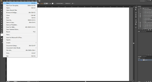
First We create a new file.

- Name the Document
- Then set the size of the document.
- in out case it doesn't matter as we are going to export shape and not as a document.
- Set everything else as default.
- Press Ok and we have our blank document.
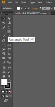
Now to Create a square we select the Rectangle form the
Tool panel.


Once we I Draw the basic shape I realized we need to change the Unit form pixel to mm to able to understand what size we are making for
We have options like
- points
- Inches
- Millimeters
- centimeters
- and pixels
We can See the value now appears in MM
Next Increased the line width to 4pt (PX)
Now selected the Text filed as hows in image.
we can select other options.
but this is the normal type tools for left to right typing.
Select the Correct Front.
We can set various options for formate the text correctly.
Next I Converted the Text to Outlines.
This is to Septate each text and to use it a a vector instead of text formate.
We cannot change font style after this step as it gets converted to a Vector Shape just like the Rectangle we Draw earlier.
Now we Ungroup the shapes.
Now we can Move Each character separately by just selecting it.
I used the Vertical Distribution tools to arrange letters. at equal distance.
Next I used the Pen Tool to draw a triangle manually
Now we can use export option to export in various formates.
But for Vinyl cutter we need EPS formate which is a standard scalable vector formate which the cutting software will understand.
FILES FOR CUTTING
LEARNINGS OF THE ASSIGNMENT
- During The Duration of FAB Academy I have learned Fusion 360 a little better then before
- Rhino is something I haven't even heard off.
- I have Learned Rhino and have used it so much that, now I am confident on working with it then on Fusion 360.
- Learned the Limitations and Possibilities with both these software.
- My Biggest Take Away at FABAcademy is from Learning Rhino.
- Learned Illustrator further.