"EX-TERRA-DUR" Terracotta Clay Extruder
CONCEPT:


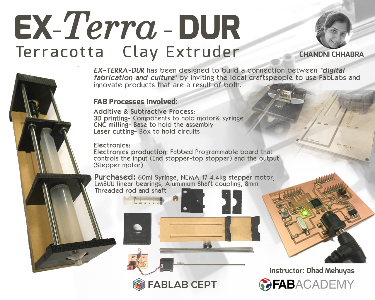
EX-TERRA-DUR is an extruder that extrudes Terracotta clay. Terracotta is locally available in my country 'India'. As a material, terracotta has been used by craftspeople all over the world to fabricate cultural products. Also, it has different consistency and composition than ceramic clay and is sustainable too.
My idea is to make an extruder using simple components and 'Fab-able' , so that the local craftspeople here can make it and use and this could make a "connection between digital fabrication and culture" by inviting craftspeople to use FabLab to produce cultural products.

Video of Ex-Terra-Dur extruding Clay:
Acknowledgements:
Thanks to Jari Pakarinen. The circuit that he designed for stepper motor using A4988 motor driver acted as a base for my board.
Mohit Ahuja, Jimish, Dhruv Saidava & Gautam Prakash helped me programming the board
Rudrapalsinh Solanki guided me with mechanical design for my extruder.
Bill of Materials:
.jpg?crc=372290889)
TOTAL: 3500 INR
The bill of materials can be accessed here.
FEEDS FROM WEEKLY ASSIGNMENTS:
LICENSE (Week 18):
Human-readable summary of (and not a substitute for) the license. Disclaimer.
You are free to:
Share — copy and redistribute the material in any medium or format
Adapt — remix, transform, and build upon the material
for any purpose, even commercially.
This license is acceptable for Free Cultural Works.
The licensor cannot revoke these freedoms as long as you follow the license terms.
Under the following terms:
Attribution — You must give appropriate credit, provide a link to the license, and indicate if changes were made. You may do so in any reasonable manner, but not in any way that suggests the licensor endorses you or your use.
ShareAlike — If you remix, transform, or build upon the material, you must distribute your contributions under the same license as the original.
No additional restrictions — You may not apply legal terms or technological measures that legally restrict others from doing anything the license permits.

EX-TERRA-DUR by Chandni Chhabra is licensed under a Creative Commons Attribution-ShareAlike 4.0 International License.
Based on a work at http://archive.fabacademy.org/archives/2017/fablabcept/students/203/.
Computer Aided Design: (Week 2)
My initial idea was focused on making a 'Clay printer' but later after the suggestion of my local guru Ohad Mehuyas, I concentrated the idea to make a 'Clay extruder'.
I modelled my initial idea of Clay printer during my week 2. Later, I also added files for my revised 3D files for final project-Clay Extruder. I created a few rendered images to understand the assembly and the final structure of the extruder. The images can be seen below and more details can be found on the project development page:


3D view of the extruder
Exploded view of the extruder
Electronics Design:
Based on the knowledge gained during the electronics design week, I designed a custom board for extruder called the 'TERRAPIN' board. I did a few trials before designing the TERRAPIN board, that controls both my input and output device of my extruder.
My initial trial was to make a board that could control the Bipolar stepper motor that I used to push the plunger of the syringe. The board turned out to be successful which encouraged me to design a board that included networking between my input and output device. I made this board as part of the 'OUTPUT DEVICE' assignment. I also tried to develop the input device for my extruder in the INPUT DEVICE week. I included the sketch within the schematic of my final board.
Further I, developed a board that could control my input and output device (Terrapin). The images below are of the final board I used for my TERRAPIN board.


FABRICATION PROCESSES:
Laser Cutting (Week 3):
I decided to prepare a box to conceal my circuit and integrate it in the device. Hence I chose to use laser cut 2.5 mm thick MDF board for this.
Preparing the file for cutting:
I made a box in reference to my device such that it can be mounted onto the back plane. Istarted by making 3D using Rhinoceros 3D and then extracted the 2D files by using the command 'Make 2D' in Rhinoceros. The images below show the process of preparing files in Rhinoceros.

3D Printing (Week 5):
After finishing my 3d design I decided to start fabricating all the parts of my extruder. All the components are very simple and as I wanter to keep my extruder lighter I decided to 3D print all of them with ABS.
Preparing the file for printing:
While designing the extruder components I made all the components in such a way that they can be fabricated easily through 3d printing and the removal of the syringe. I started by making 3D using Rhinoceros 3D and then extracted the 3D files by export command and converted all the files in stl format. The images below show the process of preparing files in Rhinoceros.
.jpg?crc=3832990149)
.jpg?crc=3793606189)
.jpg?crc=4249942334)
.jpg?crc=3975024370)
<
>
Images of components being 3D printed.

711x400.jpg?crc=248046481)
711x400.jpg?crc=3892190147)
711x400.jpg?crc=3862781770)
711x400.jpg?crc=260071018)


<
>
CNC milling:
Once all the 3D printed components are ready, I decided to finish my major component where my other 3d printed components will fix and my motor will be supported.
Preparing the file for milling:
The base of the extruder is designed in such a way that, it becomes most important member and holds all the other members of the extruder. The images below show the process of preparing files in Rhinoceros.
Images of components being 3D milled:


03. Electronics and coding:
I required a circuit board that would help me run a Bipolar stepper motor for my 'Clay extruder'. I wanted to redesign the board designed by Neil, but unfortunately the ICA4953 motor driver required to run the motor wasn't available in my area. Hence, I was trying to make a circuit using A4988 motor driver.
I started by modifying the Satsha-kit and added the required components based on the connections that I understood from Jari's board. I came across Jari Pakarinen's work for FabAcademy 2017 and found out that he had prepared a board using the A4988 motor driver to run a bipolar stepper motor. Hence, I decided to redesign the board and try it myself to see if the board was helpful.
I added provision for 12V power supply that would power up my IC and the IC would further supply power to the motor. Also, Satshakit had a lot of pins, which I reduced depending on the connections that I would require for my end stopper and top stopper. Initially I added a voltage regulator to maintain the current flow to the IC. I removed it later as it was not required in the circuit. I could directly power up the IC to transfer power to the motor.


Below are the images that show the milling process and stuffed board:


<
>
Programming:
I prepared the codes to run the board.The codes I used are attached below and the video showing the working of the code can be seen beneath the codes.
// codes for TERRAPIN board " EX-TERRADUR"
// codes by Chandni Chhabra
//http://archive.fabacademy.org/archives/2017/fablabcept/students/203/
const int stepPin = A1;
const int dirPin = A0;
const int topStopper = 3;
const int bottomStopper = 4;
void move( int times, int stopperToLookFor ){
// loop stayes 'times' times.
// One Loop iteration moves motor aporx 8.4 millimeter
while( times-- ){
for( int x = 0; x < 200; x++ )
{
// check for inputs from stopper To Look For
if( digitalRead( stopperToLookFor ) == HIGH )
{
// if stopper sends HIGH, Means plate has reached to its end
// so simply return back to the parent loop function
return;
}
//make some step with motor
digitalWrite( stepPin, HIGH );
delayMicroseconds( 2000 );
digitalWrite( stepPin, LOW );
delayMicroseconds( 2000 );
}
}
}
void setup() {
// Sets the two pins as Outputs
pinMode( stepPin, OUTPUT );
pinMode( dirPin, OUTPUT );
//set two stopperButtons as output to reduce high voltage.
pinMode( topStopper, OUTPUT );
pinMode( bottomStopper, OUTPUT );
}
void loop() {
digitalWrite( dirPin, LOW ); //Changes the rotations direction
// if move is performed 10 times, it will move about 8.4 CM which is a littlebit less than height of the injector
move( 2, topStopper );
digitalWrite( dirPin, HIGH ); //Changes the rotations direction
move( 2, bottomStopper );
// terminate the process after single execution of the sequence.
exit(0);
}
Stating the pin numbers of the respective, step, direction from the A4988 IC and stopper switches connected to Atmega 328P on the board
Movement for the plane that pushes the plunger:
Commands for the Plane that pushes the plunger to look for the top stopper button and then count the number of steps to move forward.
Functioning for the end stopper and top stopper:
Commands for the top stopper and end stopper act as switches for the functioning and movement of the motor to move the plunger plane upwards and downwards.
The below diagram can be referred for pin numbers:

More details can be found on Project Development page.
EX-TERRA-DUR by Chandni Chhabra is licensed under a Creative Commons Attribution-ShareAlike 4.0 International License.