FabLab Cept
FINAL PROJECT IDEAS
There are various examples around the world for responsive installations and also facades, where these structures have been designed to respond to movement, light, touch, sound, wind, etc.


This interactive LED light installation is designed by Shanghai-based Super Nature design.
Aedas Architects have designed a facade responsive to sun for Al Bahar Towers , Abu Dhabi
These examples along with many more are inspiration for me.
I want to develop a prototype which displays different patterns of light when someone approaches it, and it will show some movement or transformation of form when someone touches it.
Following are few sketches describing my idea for the final project. I am still not sure about the component that I want to design, so I have used triangular origami pattern to give a basic idea of the functioning of the installation.
1. The default form when a person is outside the range of sensor.

Range of sensor
2. The lighting turns on when a person gets inside the range of sensor.

Range of sensor
3. The form of the installation changes as soon as a person touches it.

The process
I had made a 3d simulation using kangaroo and grasshopper plugins in Rhino during weekly assignments, to understand the potential geometry of my installation. You can find the details here.

I used a sheet of paper and using vinyl cutting machine, I replicated the digital simulation into physical model to understand the ridges and valleys. Folding them properly, I could get a basic paper model working.


While researching on the mechanism , I came across a video with similar folding movement. Here is the link.
.jpg)
Here, 3 motors have been used to move the 3 flaps individually.
I wanted to design a mechanism where folding of these 3 surrounding triangles can be controlled by 1 servo motor. Hence,, I started my own experiments.

So, I designed a mechanism in Rhino, and prepared files for lazer cutting.


Once the laser cutting was done, I assembled the parts and using Arduino, I could run the attached servo. Initially I used Delay of 1000ms. Next, I decreased the delay to 100ms to increase the speed.
I used the reference code from the below link:
Final project _01 from Arpi on Vimeo.
final project_02 from Arpi on Vimeo.
Next step I added a junction box to fix the motors in the above system so that my servos can be fixed to the base.

I had designed 3d printed hinges in weekly assignments, I used the same with series of modifications. Process of designing the 1st prototype can be found here.
.jpg)
3d printing from Arpi on Vimeo.

1. Shifting the hinge to center and rounding of the edges to smoothen the movement.
2. Reducing the material.
3. Modifying the geometry and rounding of the remaining edges.
4. Shifting the holes to accomodate the holes on the mdf panels.
After preparing the above components, I used laser cutting to create prototypes
Laser cutting from Arpi on Vimeo.

Next step was assembling these parts and attaching the servo and testing the code. I used Arduino board to run the initial testing.
VID_20170615_003254 from Arpi on Vimeo.
Since this component was working, I decided to assemble other components to form my entire system. Total 6 modules form 1 system


Assembly 1
Assembly 2
Assembly 3
3 - 3
<
>
This assembly was yet to be connected entirely, they are 6 modules only placed together. So before joining all of them, I decided to test connecting only 2 of them and check the code.
VID_20170613_171247 from Arpi on Vimeo.
The code worked perfectly well as long as I gave signal through a single pin, For this I used a breadboard, to give common voltage, ground and signal to both the servos.
I connected all 6 servos to the breadboard giving common VCC, GND and signal pin. But it failed to move. Here is a video of the failure
VID_20170615_041749 from Arpi on Vimeo.
Following were the major reasons for this failure:
1. Power provided was not enough for 6 servos. Hence I decided to give external power supply using controlled voltage.
2. Torque required was little less compared to the torque produced by 6 SG95 servos. This was because of additional connections between adjacent modules produced more restraint. Hence, torque required for the movement increased. To combat this, I decided to use 3 servos with higher power , MG 996R.
Following these 2 measures, the movement problem was fixed.
VID_20170617_212825 from Arpi on Vimeo.
VID_20170617_215657 from Arpi on Vimeo.
Next step was to create own board for input output device.
I used the reference of Satshakit board and modified it to generate my own board.Gautam and Mohit helped me in this process.
.jpg)
.jpg)
.jpg)
.jpg)
.jpg)
.jpg)


-crop-u4771.jpg)
-crop-u4780.jpg)
-crop-u4789.jpg)
-crop-u4798.jpg)
-crop-u4807.jpg)
-crop-u4816.jpg)
Satshakit for reference
Adding component for power adapter
Removing extra pins
Adding Reset pin for AtMega 328p
Further removing extra pins and adding pins to accommodate 2 distance sensors and 1 relay
Final board and schematic
Finally I started the milling process
These are the milling settings I used
8 - 8
<
>
Final board and schematic can be found here.
Next step was to solder this board. My first soldering did not go quite well, because I by mistake put AtMega 328p in rotated direction. Hence the board was rendered useless.

I milled another board and soldered it again. This time I checked everything with Multimeter and luckily my board was working. I used Arduino ide to burn the bootloader and then my board was ready for programming.

Next step was to program this board. Viraj helped me with the programming.
Following images show the process I followed. Final Arduino code can be found here.
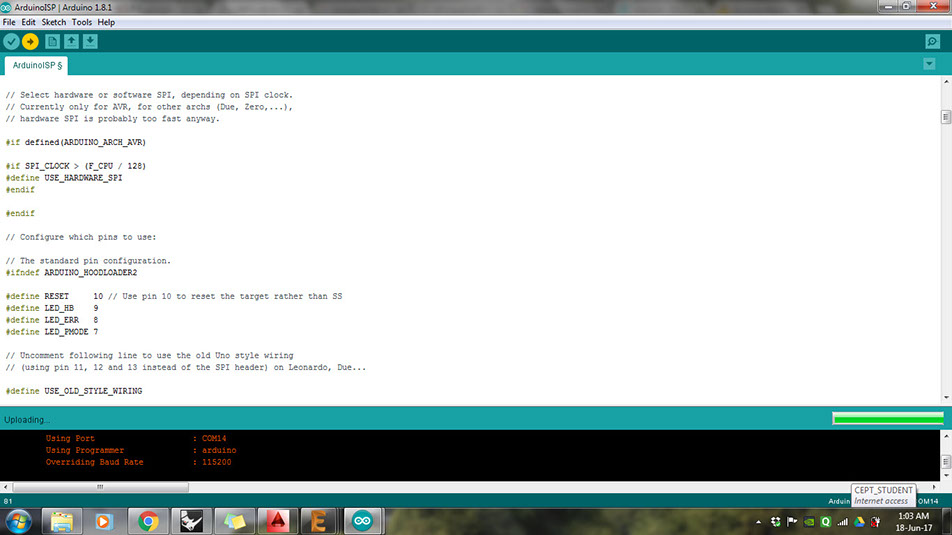


First step is to run the "Arduino as ISP" code so that Arduino can be used to program my own board.
This image shows the process followed
Next set board as "Arduino Uno" and change to programmer to "Arduino as ISP" and burn the bootloader.
Next I worked on developing a code to run the servo detecting th e distance data generated as output from distance sensors.
The code included triggering of LED light once someone approaches the distance of 100cm . And once the distance is reduced to 40cm, the servos start moving.
6 - 6
<
>
The last step was to create a box for the base of the installation. I designed a CNC box. Details of which can be found here.

The box was designed to encase the circuits and lift the installation above ground. It also had necessary holes for passing the wires.
Here are some videos of my final project.
VID_20170626_234423 from Arpi on Vimeo.
final project_a from Arpi on Vimeo.
License

This work is licensed under a Creative Commons Attribution-NonCommercial-ShareAlike 4.0 International License.
All the files can be found here.
Presentation.png
Presentation.mp4