Electronics Design
Assignment
This week assignment is to create an echo hello-world board( the following board) using redesign with extra additional components (at least two) LED and switch using.

Microcontroller
microcontroller is a control device which incorporates a microprocessor.for the studying purpouse i am refered the ATtiny44 microcontroller’s data sheet.the data sheet have more discription about microcontroller like the pin configuration with pin description ,overview ,some general information ,AVR architecture,about the memories like that
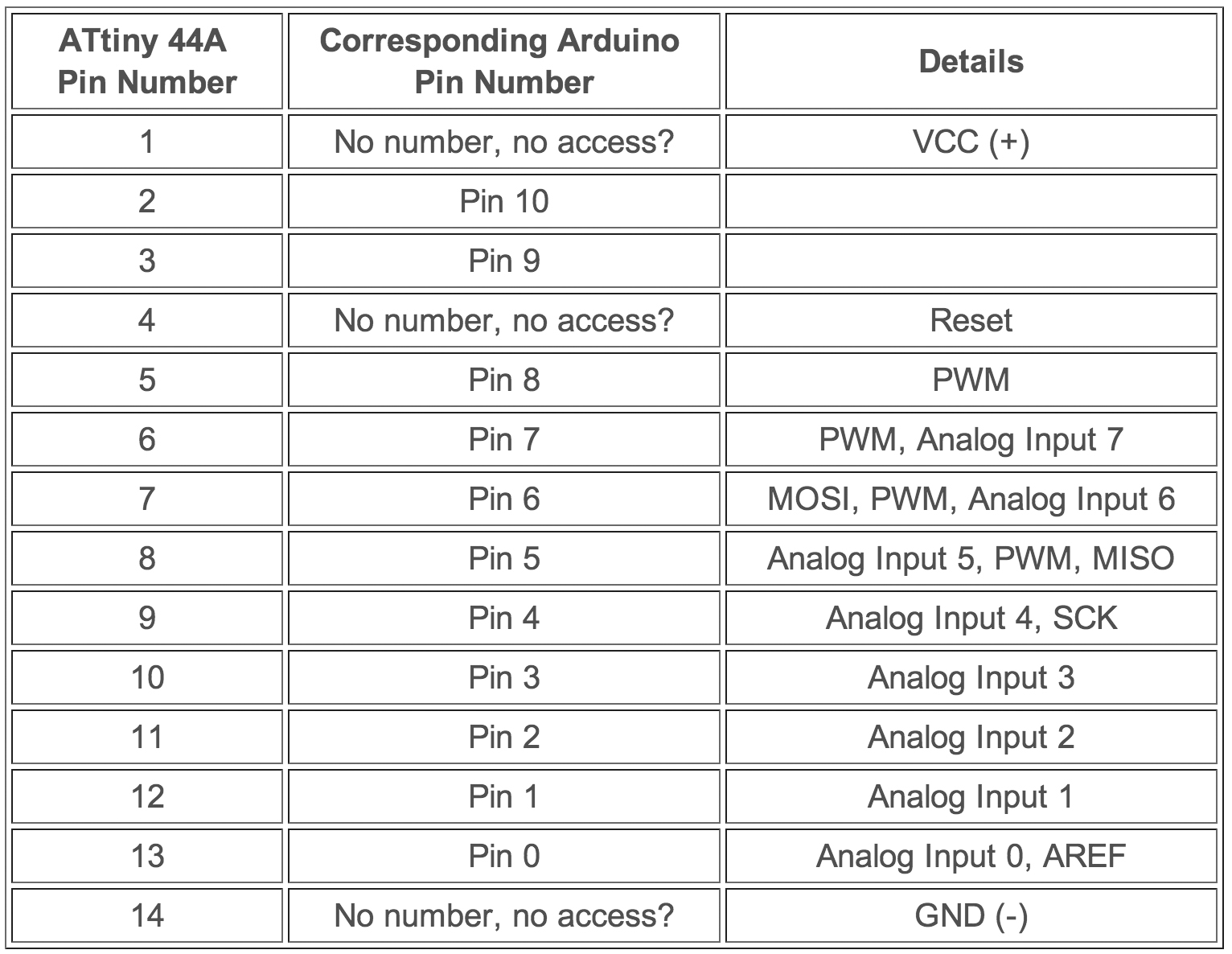
pin configuration of Attiny44

pin description
VCC - Supply voltage.
GND – For grounding pins.
PORTB(PB3:PB0) – Port b is a 4-bit bi-directional input and out put port.in that PB3 which has RESET capacity also it is used as an input or output pin.
PORTA(PA7:PA0) - Port a is 8-bit bi-directional input or output buffers have symetrical direction.
Overview
connection reuirment of a attainy programmig
six wires isp programming
SCK(serial clock):programming clock,generated by the In-system programmer(Master)
MOSI(Master Out-Slave IN):Communication line from In-system Programmer to target AVR being programmed
MISO(Master in-Slave Out):Communication line target Avr to in system programmer
GND(common ground):it connect to the ground
RESET:to enable in-system programming
VCC:to allow simple programming of targets operating at any voltage,the in-system programmer can draw power from the target .
general information
Input and output packages
20-pin qfn/mlf
14-pin SOIC and PDIP
12 prorammable input and output lines
Operating Voltage
. 1.8-5.5V
2.7-5.5 V
Speed Grade
0-4 MHz @1.8-5.5v
0-10 MHz @2.7-5.5v
Industrial Temprature Range
40 degree c to 85c
What I Did?
I think a plan to redesign the above board in adition to that,two LED and a switch add in the board.
LED circuit diagram

for the resistor calculation ,I used resistor calculator and I get the result is 470 Ohm then I use two 499 ohm resistor because I am adding two LED in this circuit.
components
Then my components list are ready for the designing process there are
-
Attiny44
-
20mhz resonator
-
10k resistor
-
499 ohms (2)
-
1uF capacitor
-
6 mm switch
-
LED(2)
-
FTDI SMD Header
designing
For the electronic design, there is using the different type of software .
In here I am chosen eagle software for the designing purpose .eagle software it is
a new one for me that is why I am searched some youtube tutorials and
fab academy tutorial.the next stage is I want install eagle,eagle installation is successful then I download the (fab library) and I add it in my library folder.
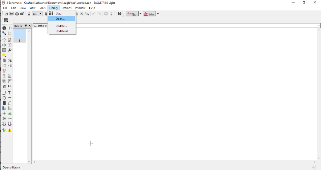
open a new project,inside of that open new schematic(when we are adding or connecting process are doing the schematic page) for opening the fab library
click “library->use” then select the fab library and open it
for adding the components in the schematic page, type “add” in the comment box then enter it that time the eagle library are open in that we click the fab,we can see components are directly under the fab folder ,In that choose what are all the components we needed and add it to the schematic page
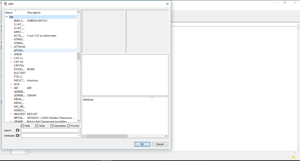
Then I select what are all the components are wanted and I add one by one in schematic diagram

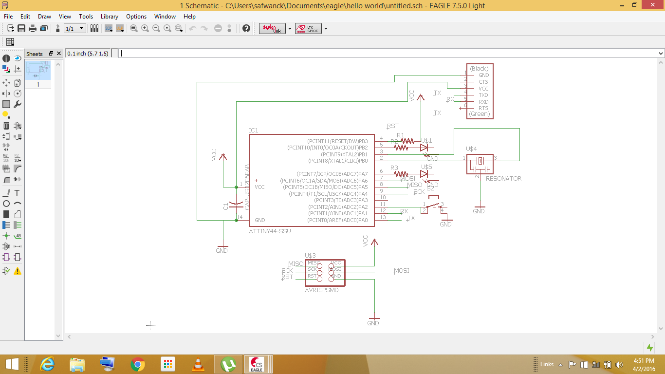
The “net” tool is used for the connection process but it is so confusing for connecting all the components,with the help of creating keyboard shortcut and “net” tool is used to completed the connection process. Here is my final schematic diagram
switch to board
when we designing time we have to want to be set some design rules another wise we can not get correct designs.

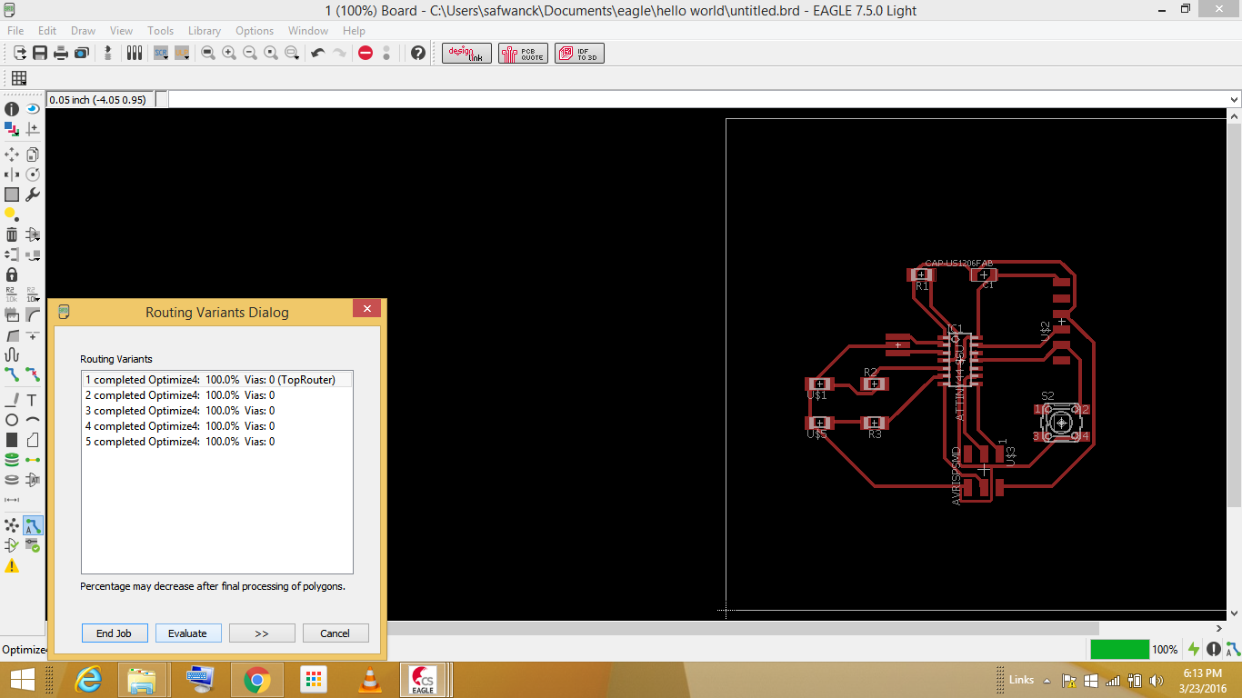
the board designs are doing the switch to board view,in here we arrange the components place,board shape .after the design to check any connection problem occurs or not for that I am going to autoroute ,then I set top=auto and bottom=N/A , because I wanted a single side board and click continue that time it root automatically.but I did not to get 100% in the first time.also, we can see where is the connection problem when we rooting time and I change the place of components finally got 100%.manual routing option also has the eagle.
how to export the image
we want two images for the design one is trace image,another one is an outer image for that after the routing select layer setting in that select “top”and click ok we can see the inner image in the board

then click file->export->image
Then the upcoming box types file name and click monochrome then click “ok” same as to click “dimension” in the layer setting and do the same process again at the time we can get the cutting image
note*the exporting time we change the dimension size to 0.032
milling
then I started to the milling process for that first I loaded the trace image in the fab module apart from that I connect the 1/64 bit in the model and I started the milling process.
Inner image

the traces milling process was completed.then I load the outer part of the image in the fab module and I change 1/64 bit into 1/32
outer image
milling result

soldering
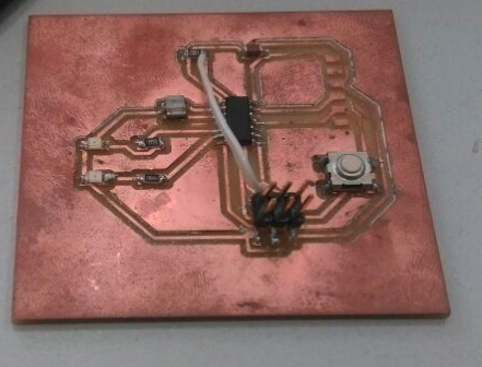
then I take what are all the components are wanted and start to soldering my soldering process is completed

I Did not get continuity why?
then after I check the connection in my soldered board but I did not get continuity in my 32 header reset button , at a time I am going back to my inner trace diagram,I found where is the problem,I am not connected ATtiny44 reset pin into 32 reset pin when the designing time,then a copper wire is used to connect the resistor reset pin and 3*2 reset pin.problem was solved :).

Final out
Orginal files
schematic :.sch file
board file :.brd file