I enjoyed this weeks lecture because I like modelling stuff using CAD and was interested to know more about it. Neil took us through a list of computer aided design software applications and explained the most important differences between them. A part of this lecture I found especially interesting was about the different concepts and methods of 3D design:
Constructive Solid Geometry (modelling by combining objects using boolean operations), hierarchical (like parent and child relation), Parametric (changing parts by changing parameters; cloned parts are updated at once) and Procedural (creating a model from a rule set, like fractals).
Boundary (b-rep) (local representation connecting faces, edges and vertices), Function (f-rep) (a solid object defined by function of point coordinates. Points with which the function generates a positive outcome belong to the object and points with which the function generates a negative outcome do not belong/are outside the object. If the function equals 0 this describes an isosurface) representations
using either GUIs, Scripting (automated task sequense software) or Hardware description languages (specialized computer language which describes the structure and behavior of electronic circuits)
Declarative (like drawing by hand on paper), Constraint based (the user specifies relationships among drawing parts), Optimizational (drawing parts are described by the outcome of a mathematical function)
Assignment
Model (sketch, draw, render, animate, simulate, ...) a possible final project using as many CAD software tools as possible and post it on your page.
The idea is to get to know the software tools and see for ourselves which ones we like the most and also which ones are most useful for the type of things we want to do.
CAD tools and process
Adobe Photoshop
I wanted to create a vector graphic from the photo of the first sketch I made in week 1.
In Photoshop I changed the image mode to duo tone to make the image black and white only. Then I played with the contrast and brightness settings and applied the sharpen function to get the image as clear as I could. I imagined that this would be a good preparation for the next step.
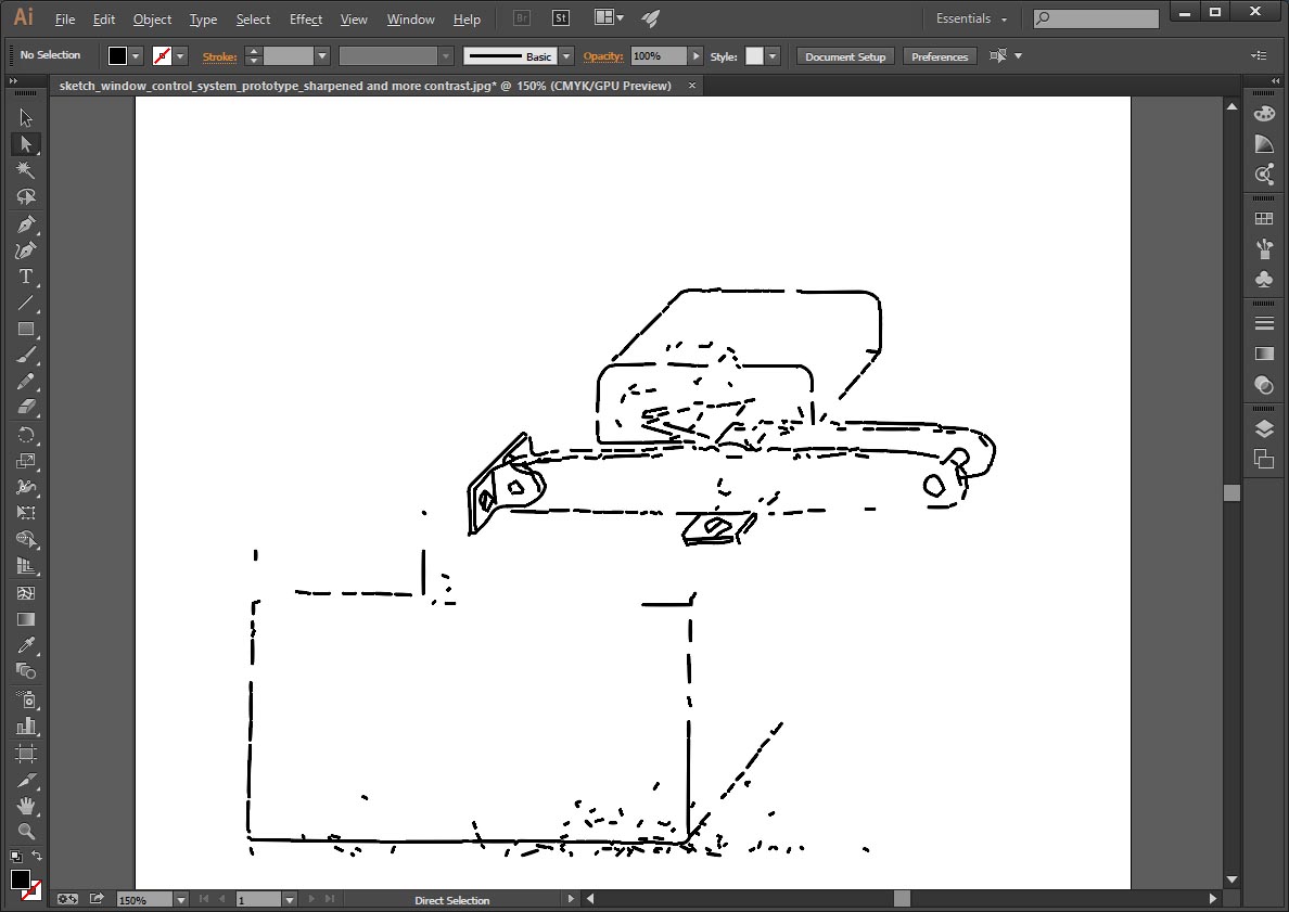
I opened the file in Illustrator where I used the image trace function which should work really well. Our instructor Cecilia Raspanti explained that other 2d vector programs like Inkscape can do it too, but Illustrator usually does the best job. In this case it did not work out well though. Even after going back and forth between Photoshop and Illustrator trying many different settings this is the best version I got is not acceptable at all:
Solidworks
I heard about Solidworks for the first time during the lecture on Wednesday and I watched a fellow student; Paul Gröneveld use it. It was impressive to see several parts in an assembly design in Solidworks to be edited and dynamically updated; proper parametric 3D modelling! It became clear that this would be one of my goals this week: Learn as much as I can about Solidworks!
Well, there is quite a lot to know about Solidworks so I watched a few tutorials so I got familiar with the particulars like what is a sketch, what is a feature, how to use the planes and how can I align two parts etc. I took measurements of the window in my house because I wanted to model my Final Project idea. In Solidwork you sketch a part first and then add the necessary dimensions and relations until it is fully defined. I started sketching a window frame and a t-strip, but going along I came to the conclusion that the first sketch that I made on paper during week 1 is not realistic. Mainly because the dimensions are not correct and there is not enough space to place the actuator arm the way I sketched it! You can see below that after I modelled a t-strip and placed it on the window frame, there is hardly any space left for an arm between the t-strip and the window to operate it. The animation on the right was created using Solidworks MotionManager which outputs .avi files compressed with the Microsoft Video 1 codec. I used cloudconvert.com to convert the video format to mp4 so most browsers can natively play it using HTML5, so no plugin is needed.
t-strip on frame source file - Solidworks (I lost this file, mistakenly overwritten with an empty file..)
At this point I felt stuck at first, but then I decided to further develop the modelling of the frame and the window first and not spend time on thinking of another mechanism or actuator type right now.
It will be useful to have a 3D model of a working frame and window with which I could simulate the movement of the window. I hope I can add an actuator mechanism later once I have better ideas on how to do that technically.
So after many hours of trying to get it right, watching more tutorial videos and also asking Paul for help while his wife and daughter where waiting on him on the couch to watch a movie...
ツ
I managed to get to this result:
Inkscape
To prepare for Fabacademy I watched a few tutorials about Inkscape and experimented with it. I also drew a lamp that hangs in our kids' bedroom. The lamp front is made of 5mm plywood and I found an image of it at a web shop.
I traced the curved lines with the bezier tool and also added curved text (text menu - put on path) for the name of a friends' baby boy called Jaime. Maybe I can build the lamp as a present later!
Rhinoceros (2D)
The tree lamp has a part on the rear side which contains the actual lamp fitting and also acts as a wall mount for the whole lamp. Making this tree lamp could be a nice project on the lasercutter! This would need a 2D vector file, and the fitting case dimensions need to be really exact because it is a press fit box. Drawing this was a perfect exercise for me to do in Rhino which has a more mathematical approach then Inkscape or Illustrator. Rhino is also a 3D modelling tool, but for this I did not need 3D. Because of my experience with AutoCAD many years ago, Rhino was not hard to start using. Below you see my drawing of the lamp fitting case in Rhino.
Rhinoceros (3D)
After I finished the 2D drawing I was curious if I could go into 3D! To start modelling I took a Lego block as an example piece. I measured it by putting 10 Lego blocks in a row and then dividing the measured value by 10. This is more precise then trying to measure one Lego block. Modelling this took me quite a while, but eventually I made a virtual Lego block!
Antimony - CAD from a parallel universe
The first thing I did this week was installing CAD software like Solidworks and Autodesk Fusion360 (did not get to trying that one out yet). Also I installed Linux Ubuntu as a dual boot second OS next to Windows7 on my laptop to be able to install Antimony. This is a CAD tool based on Function representation (f-rep). I gave it a first try, but I would like and need to spend more time understanding this totally different approach to CAD drawing to be able to model something properly. As it says: from a parallel universe!


 sketch source file - Illustrator


