Wk11: 2016/04/13
INPUT DEVICES
0. Assignments for wk11
The assignments for wk11 were as below;
- Measure something: add a sensor to a microcontroller board that you have designed and read it.
1. Practice on Arduino
For final project, I would like to make "Lost Property Prevention Attachment", with GPS, motion sensor/accelerometer. However, handliing input device was totally new to me, so I decided to get familiar with embed programming with input device this week using "piezo" which can sensor vibration.
Piezo
Piezo
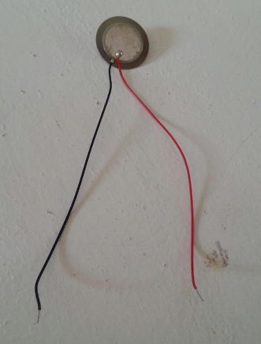
Piezo is an electronic device that can both be used to play tones and to detect tones.
First, I wanted to know the function of the sensor, so examined it using Arduino UNO without selfmade board. I found the very good tutorial which I was just trying to do; Arduino Tutorial: Knock sensor, so mainly proceed the test following this tutorial.
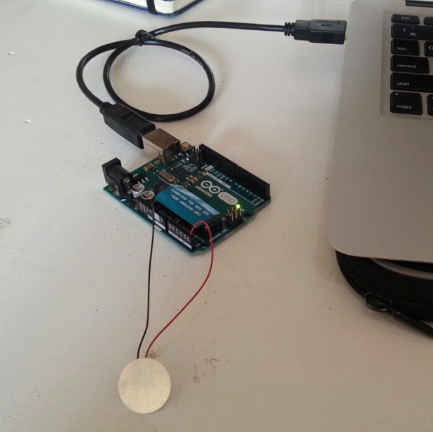
Arduino Test
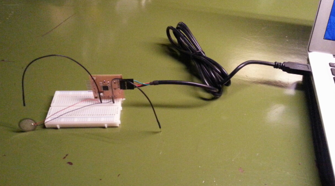
As the picture above shows, I plugged the Piezo on the analog input pin number 0 and ground. Piezos have polarity, commercial devices are usually having a red and a black wires, and I connected the black one to ground and the red one to the input.
Analog input
Ex. analog input on Arduino supports the functionality of reading a value between 0 and 5volts, and not just a plain HIGH or LOW
Digital input
xxxxx
ADC - analog to digital converter
Analog to digital converters read a voltage value and transform it into a value encoded digitally. In the case of the Arduino boards, we transform the voltage into a value in the range 0..1024. 0 represents 0volts, while 1024 represents 5volts at the input of one of the six analog pins.
Test1: Serial Output
Next, I wanted to know the how the sensor output the value to the serial monitor, so wrote the very simple code set as below.
/* Measure the value of Piezo
 */

int knockSensor = 0;
byte val = 0;

void setup() {
 Serial.begin(9600);
}

void loop() {
  val = analogRead(knockSensor);
  Serial.println(val);
  delay(100);  // we have to make a delay to avoid overloading the serial port
}
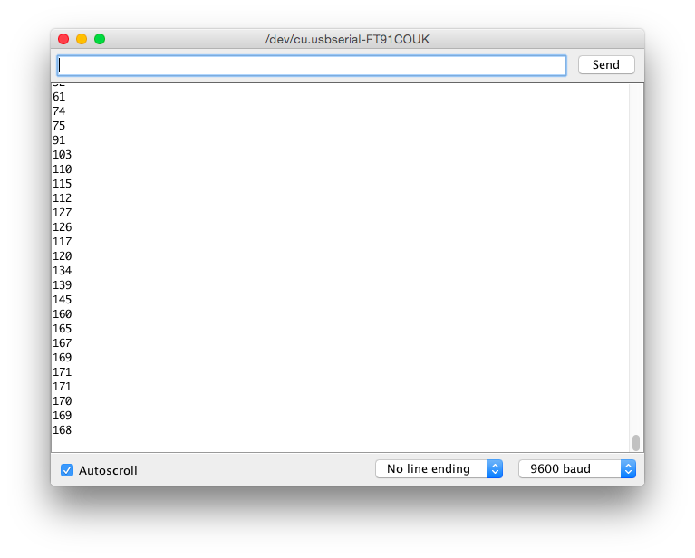
Then I could successfuly get the value which the sensor measured on serial monitor.
Piezo parameter on serial communication
Test2: Knock test
In addition to that, I wrote the "Knoch sensor" code with reference the previous tutorial, which posted the message "Knock!" to the serial monitor if some moment above set thereshold was added to the sensor.
// Knock Test

int ledPin = 13;
int knockSensor = 0;
byte val = 0;
int statePin = LOW;
int THRESHOLD = 80;

void setup() {
 pinMode(ledPin, OUTPUT);
 Serial.begin(9600);
}

void loop() {
  val = analogRead(knockSensor);
  if (val >= THRESHOLD) {
    statePin = !statePin;
    digitalWrite(ledPin, statePin);
    Serial.println("Knock!");
  }
  delay(100);  // we have to make a delay to avoid overloading the serial port
}
2. Making Fabkit
What is 'Fabkit'?
'Fabkit' is an Arduino-compatible board designed by David Mells and based on an ATMEGA microcontrollers, which are more powerful microcontrollers provided by Amtel than ATtiny models. With this board, we can write code with an Arduino IDE (and all of its libraries).
Though the 'hello echo board' is one of the simplest boards that consist of an input (switch) and an output device, 'Fabkit' is a more capable board with more connectors and fitting boards with either simple or complicated input/output devices.
To make 'Fabkit', the following tutorials are raher vital that very useful.
Milling, soldering and debugging
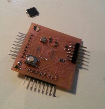
I straigtforward followed the tutorials above and procceded milling and soldering. I used Amtel: ATmega328P though it was different from the microcontroller that was used in the tutorials because there were not remaining stocks and Emma, who was our instructor, said that it can work tottaly same.
Though soldering the microcontroller was really difficult because the pin was incrediblly small, I was able to manage it and completed to make it.
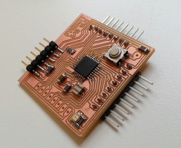
Fabkit
Connecting with USBtinyISP
Though Fabkit can work almost same as Arduino, Fabkit have to be burned bootloader by USBtinyISP, then it was necessary to connect Fabkit to USBtinyISP. However, the configuration of their PIN were a bit different with each other, so I had to identify the correct pin configuration to connect.
First, I looked the connector configuration/blueprint of FabTinyISP and identified what the functions of each pins are.
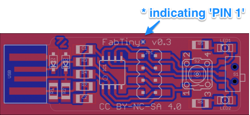
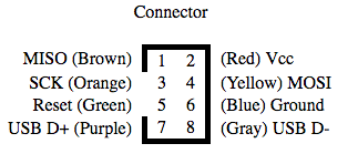
Blueprint/Connector configuration of FabTinyISP
Next, I reserched the ATMEGA328P and schematic of Fabkit as below and managed to identified the pin configuration for 6 pin connectors, which was for connecting to FabTinyISP.
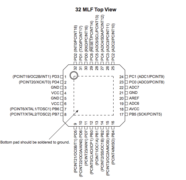
PIN configuration of ATMEGA328P from its datasheet
PIN configuration for 6pin connector
Finally, I successfuly connected Fabkit with FabTinyISP as below. If the connection is wrong, the parts on board sometimes get very hot and wrong, so correct connection is really important.
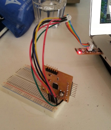
Fabkit connected to USBtinyISP
Burning bootloader
Next challenge was burning bootloader of Fabkit by FabTinyISP.
As I did in embedded programming week, the initialization and testing the conection was what to do first. Putting the UNIX command;
avrdude -c usbtiny -p m328p
to terminal, it tells us if the connection is clear or NOT.
This time, the problem occurred and somehow I was not able to clear this test... Though I asked Emma to help and we checked all the connection between the two, we could not identify the problem. Then, I could not help changing the microcontroller to new one. (Solderting again, it was really long way...)
Changin the microcontroller to new one
After substituting the microcontroller, I could pass the test in the end. The cause seemed that the previous microcontroller was something wrong.
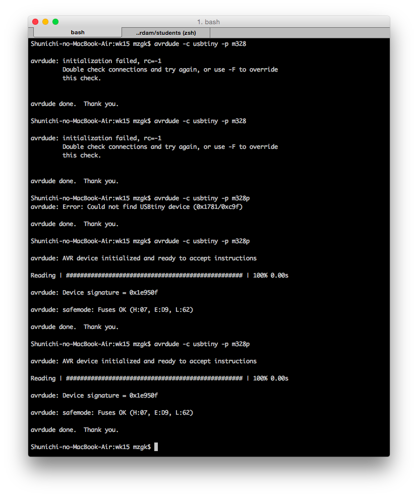
Succcessful initializing/testing
In this case for burning bootloder, the exact setting was as below;
This setting is really important if you use wrong setting, it will not work.
- Board: "Arduino UNO"
- Programmer: "USBtinyISP"
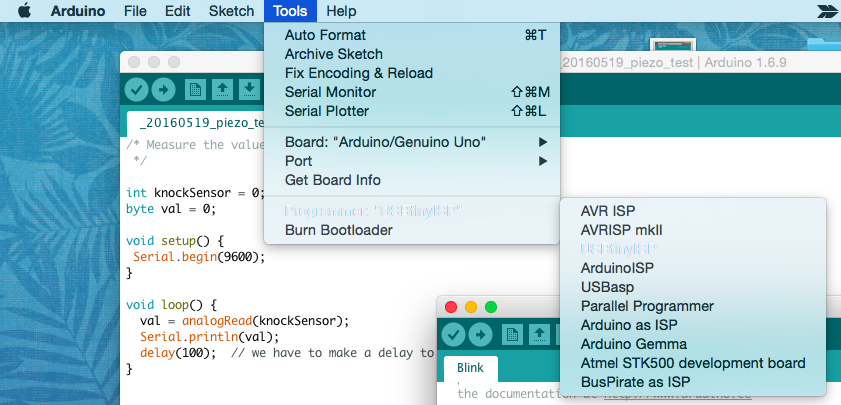
Setting on Arduino
When you try to burn bootloader, you must keep pushing the 'RESET button' on the Fabkit board during the process. Then, I could burn bootloader in the end. Here, you can see the message of correct buring bootloader on Arduino command line .
Working test
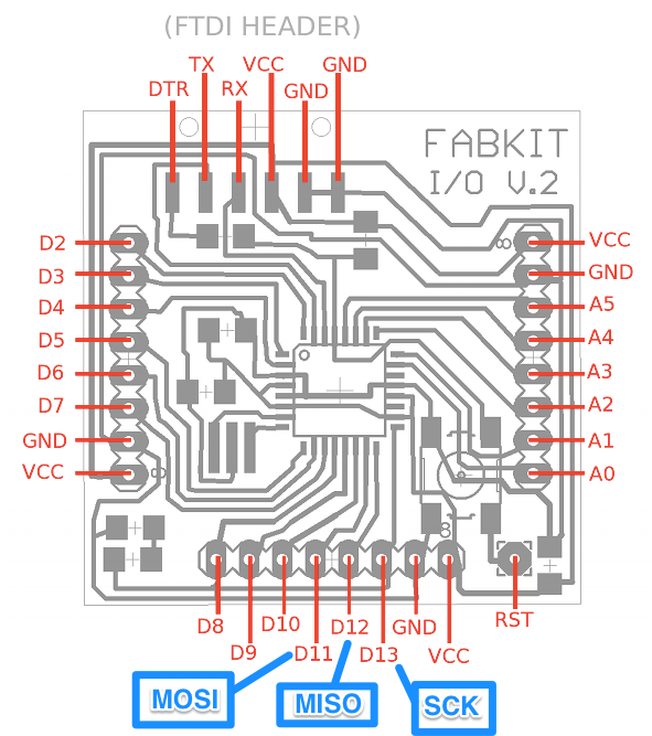
Fabkit is compatible with Aruduino and can be programmed by Arduino IDE via FTDI cable. Then, I had to connect Fabkit with FTDI cable correctlly cheking the pin configuration of FTDI cable as below.
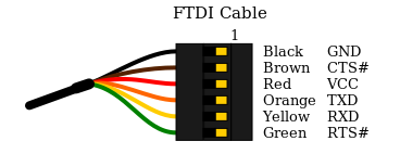
PIN configuration of FTDI cable
Next, I implmented the simple code of blinking test as below to check if Fabkit were wroking correctlly. I pointed the PIN 13 as blinking one because it was connected to LED on the circuit(please refer the blueprint above.)
void setup() {
  // initialize digital pin 13 as an output.
  pinMode(13, OUTPUT);
}

// the loop function runs over and over again forever
void loop() {
  digitalWrite(13, HIGH);   // turn the LED on (HIGH is the voltage level)
  delay(1000);              // wait for a second
  digitalWrite(13, LOW);    // turn the LED off by making the voltage LOW
  delay(1000);              // wait for a second
}
The test went well as the video below. It worked completely same as my Aruduino UNO! Then, I fineshied all preparation for enojoying programming on Fabkit.
Blinking test on Fabkit
3. Sensoring by Fabkit
I implmented the same code as the one on Arduino test; '20160519_piezo_test.ino'. I paid attention to the connection between the board and piezo checking the pin configuration of Fabkit. I plugged other wires to the same hole in which ones of piezo were plugged because the wires of piezo was too thin to keep the connection stable.
Fabkit with piezo
Writing the programme on Fabkit, I got the same result as I got on Arduino test on serial monitor, and completed the assignments of input device in the end.
The result on serial monitor
4. Accelerometer Board
For the assignments this weeek, I decided to make accelerometer board, which I could use for my final project: lost property prevention device sensoring the accleration when someone tried to steal my items.
Having discussion with Emma, our local instructor, I chose 3-Axis Accelerometer: MXR9150MZ. For my project this week, I read a lot of time this past student's page: Vincent Chow: Collecting Sleep Data via a 3-Axis Accelerometer.
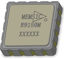
3-Axis Accelerometer: MXR9150MZ
Design the board
First, we made a lough sketch of the schematic with a lot of help by Emma. The challenge was that I had to add reguralor to decrease the voltage because the appropriate voltage for Fabkit was mainly 5V, however, that for MXR9150 was 2.7V to 3.6V according to the datasheet of MXR9150MZ
Therefore, I added a 3.3V regulator to down the voltage from 5V to 3.3V and two capacitors to stabilize the current as the sketch below with reffering the datasheet of regulator.
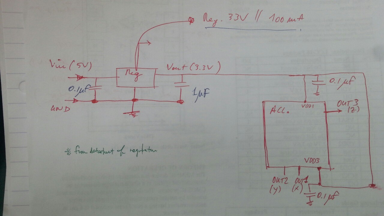
the sketch of the accelerometer board
Voltage regulator
is designed to automatically maintain a constant voltage level.
Capacitor
(originally known as a condenser) is a passive two-terminal electrical component used to store electrical energy temporarily in an electric field, and it can stabilize the current and remove noize from signals.
Adding MXR9150 to EAGLE
Next, before starting to write the schematic on EAGLE, I had to add MXR9150 to EAGLE library because there were no sketch on the internet. During the whole process, I mainly referred these useful sites below.
The process was as below;
- First, write the symbol of MXR9150
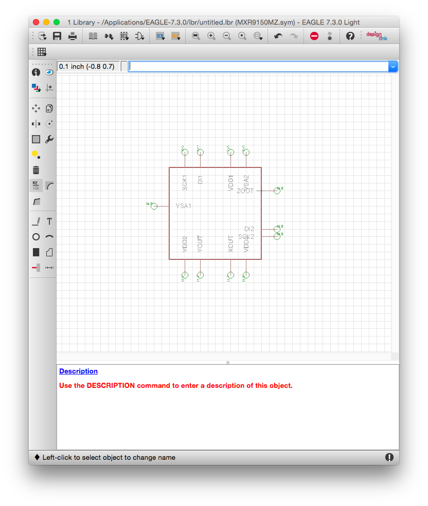
Symbol of MXR9150
- write the board for it making it corresponded with the pin configuration on its datasheet.
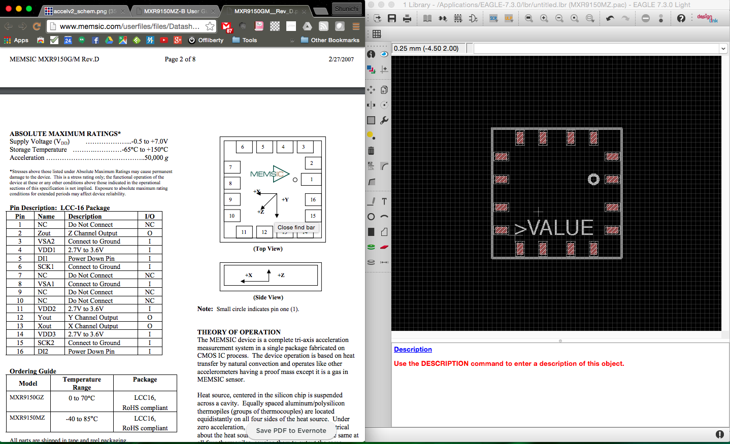
Symbol of MXR9150
- Connect the virtual symbol and the physical board
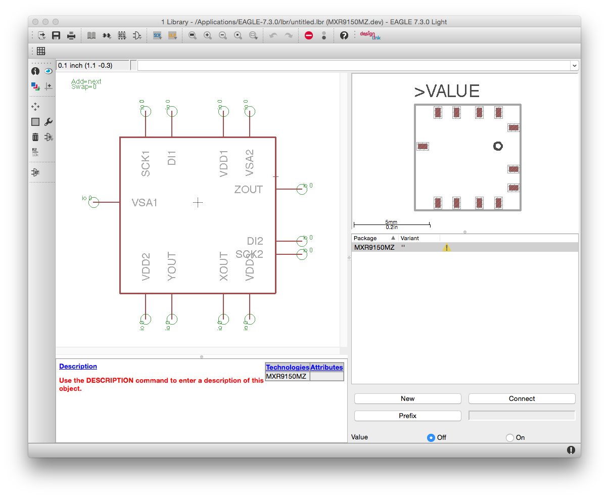
Connecting the symbol and the borad
Finally, I successfuly added the parts to EAGLE library.lol
Designing the board on Eagle
Following process was really straigtforward. First, I put parts' symbol to the sketch and connected them with each other on EAGLE, following the lough sketch above, and then made the schematic as below.
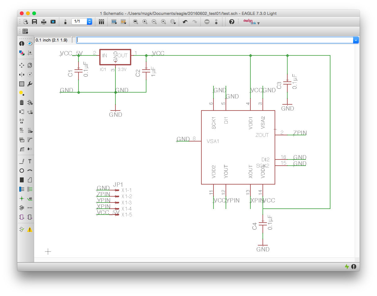
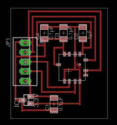
Finally, I exported PNG file for tracing and cutting by modela as below and finished the designing part.

Soldering the parts to the board
The soldering part was also finished straigtforward. Here is the accelerometer board which I made.
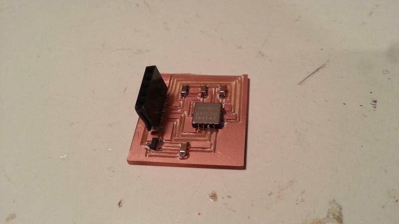
Accelerometer board
Writing the code and testing
First, I connected the new accelerometer board to Fabkit, which I made previously. As the output of parameter which accelerometer can read was analog output, I used analog pin on Fabkit and connect them with each other as below.
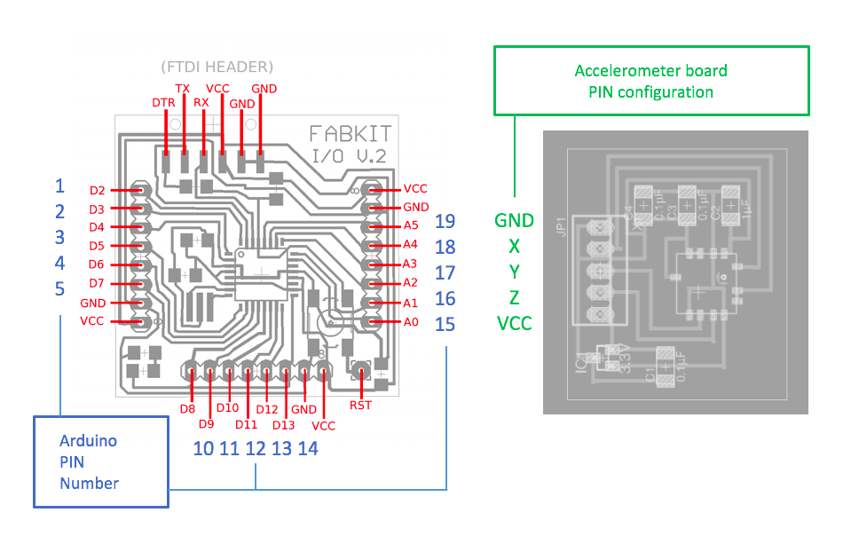
PIN configuration of two boards
Next, I wrote the test code on Arduino for checking if the accelerometer were working correctlly or NOT as below.
#includeint pin_x = 17; int pin_y = 18; int pin_z = 19; byte val_x = 0; byte val_y = 0; byte val_z = 0; void setup() { Serial.begin(9600); pinMode(pin_x, INPUT); pinMode(pin_y, INPUT); pinMode(pin_z, INPUT); } void loop() { val_x = analogRead(pin_x); val_y = analogRead(pin_y); val_z = analogRead(pin_z); Serial.print(val_x); Serial.print(", "); Serial.print(val_y); Serial.print(", "); Serial.print(val_z); Serial.print(", "); Serial.println(""); delay(100); }
Then finally, I was able to read the output of the accelerometer on the serial monitor of Arduino as below, and successfuly made the baord.
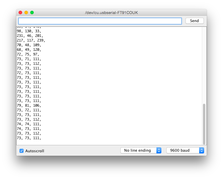
The output on the serial monitor on Aruduino
Outline of this page
1. Practice on Arduino
2. Making Fabkit
3. Sensoring by Fabkit
4. Accelerometer Board
Download output of Wk11
Here are my output files for wk11:
(Accelerometer Board)
(Programming)
(Reference: Fabkit_v02)
Lecture Material for Wk11
Lecture Note
Tools
- Piezo Element
- Arduino
- FTDI cable
- Inkscape
Learning Support
Videos of Wk11
Here you can find this weeks's lectures on VIMEO:
(2016.04.13)
(2016.04.20)
Checklist for Wk11
Assignments:
- Measure something: add a sensor to a microcontroller board that you have designed and read it.
Learning outcomes:
- Demonstrate workflows used in circuit board design and fabrication
- Implement and interpret programming protocols
Have you:
- Described your design and fabrication process using words/images/screenshots.
- Explained the programming process/es you used and how the microcontroller datasheet helped you.
- Explained problems and how you fixed them
- Included original design files and code