
Introduction
During this week we learnt the programming part of making our own boards. After having made a couple of them we were ready to program one. We read also the datasheet for the ATtiny84 Microchip and understood better what each one of the pins (the little legs) are for. One is for power, one is for ground, one acts as the reset pin and the rest can be analog or digital inputs or outputs. This is very important to know because later when using input or output devices one can't just hook them to any one of the pins. They are ad-hoc pins in most cases.
The following image shows in a very didactic way how every pin has a specific set of functions assigned. These diagram I found in the web by searching for the unofficial arduino / attiny pinout diagram but we had a full printed copy of many of them here at AS220:

We also programmed the board that we made during Week 6, when we learned how to design, mill and solder everything into one board. We had added a button and an LED light, so we could configure some sort of simple program that would enable an interaction between both. This is the quick video of what happened to the LED light when the button was not pressed and then pressed:
I used arduino to program my board with a very simple program where the button and the LED were defined and then an "IF" function was declared, where it conditioned the speed of the blinking to whether the button was pressed or not.
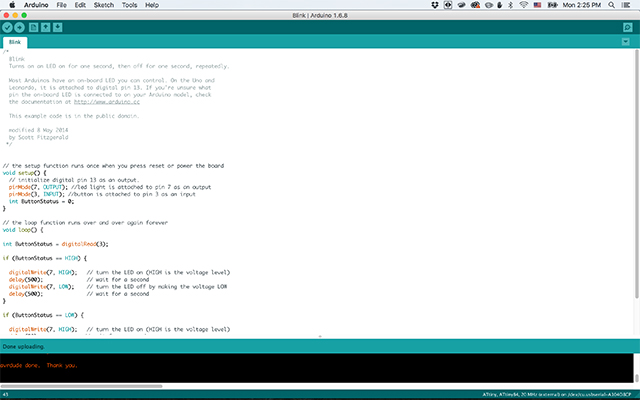
To upload the code to the board I had to use a programmer, in this case I used an AVRISP MKII, and also the board had to be connected through an FTDI cable to receive power and ground via the USB cable. .

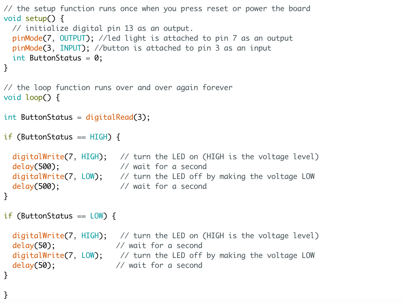
To write the code I defined in the SETUP section of the code where the button and the LED light were, in my case in pin 7 (output) and pin 3 (input). I also defined an integer labeled ButtonStatus that starts as a 0.
Then in the LOOP section of the code the integer ButtonStatus is linked to the digital read of pin 3, which can be either high or low (because it is digital). With that, I defined an IF function that sets the blinking of the light depending on whether the ButtonStatus integer is either high or low.
If the button is not pressed, the instructions are sent to the LED light to turn on, then wait *DELAY*, turn of again, and so forth. The delay is changed when the button is pressed therefore creating a faster or slower blinking depending on the situation.
This was a very simple example, but at the same time very didactic. It also gave me an idea of how much can be done with rather simple coding and with things we have at hand at the lab. Files are available to make your own!
Files
Arduino code here.