
Final Project Documentation
>>> PDF Files for the laser cutter to make Multi-Purpose Box here <<<
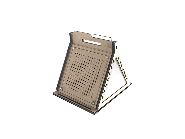
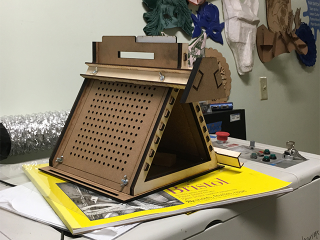
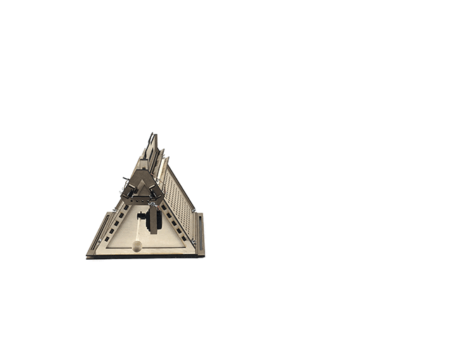
The first thing to do is the Multi-Purpose Box, when done, it looks like this:
Everything is cut on 1/8" plywood or masonite also because our laser cutter wouldn't go through 1/4" material without troubles. If you have a powerful laser cutter, some of the pieces could be cut directly on a 1/4" material.
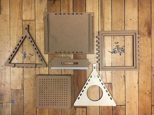
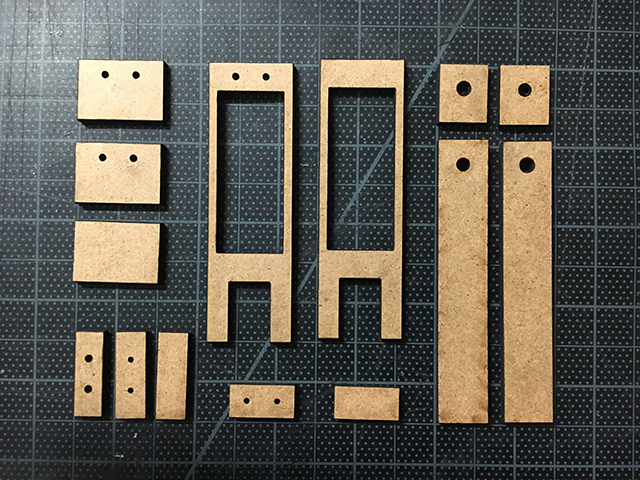
Once everything from the file is cut, the pieces should look like in the picture below. The two rectangular base files should be cut on 1/8" because they need to fit and leave an overlapping joint to achieve modularity. They need to be stuck with wood glue like in the picture. Also the cardstock pieces are meant to be use for a snugger fit, but also you could modify the holes inside the pieces to avoid the cardstock. I also used the cardstock to join the handle piece to the lateral panel into one piece, but you could also avoid it.
The screws are size 8-32 x 3/4, there is also a drawing of them in the file. And the wing nuts 8-32 size. You need 8 wing nuts per box and 12 screws and 8 normal nuts for it to work as I made it.
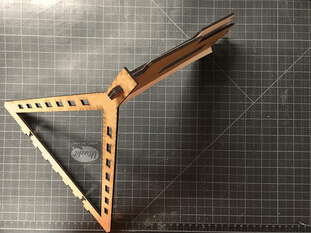
The assembly of the parts is very simple and you can follow the animation below as guidance. If you want to make this box for another use you can use different lateral and frontal - back panels in order to fit your projects.
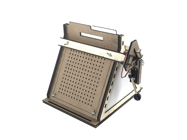
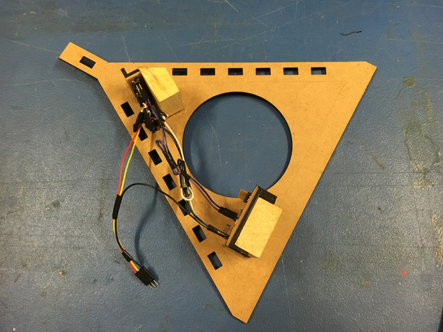
The next thing to be done is to set up the arms that will hold the motor in place. The shapes are also in the PDF file to be cut with a laser cutter. The assembly of them just requires for the three pieces to be joint perpendicularly with wood glue and then the holes should fit perfectly with the the screws on the side panels.
With these two on place you can now place the motor holder that can be of any shape, depending on your intentions. This one in particular works, but the important thing is to keep the holes in it and then feel free to modify the file.
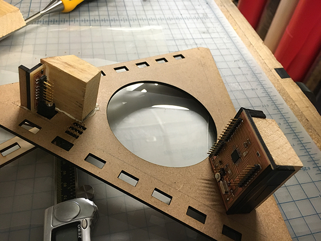
Then it is important to build the case around the Servo Motor. These are all the pieces and they are found in the laser cutter file too:
I used a Servo motor that was available at the lab and that you can also buy here. I also 3D printed an extension to adapt the drum stick to the servo motor and you can find that STL file here. And also 3D printed a sphere that could be connected to the other end of the stick to hit the surfaces. You can find that OBJ file here..
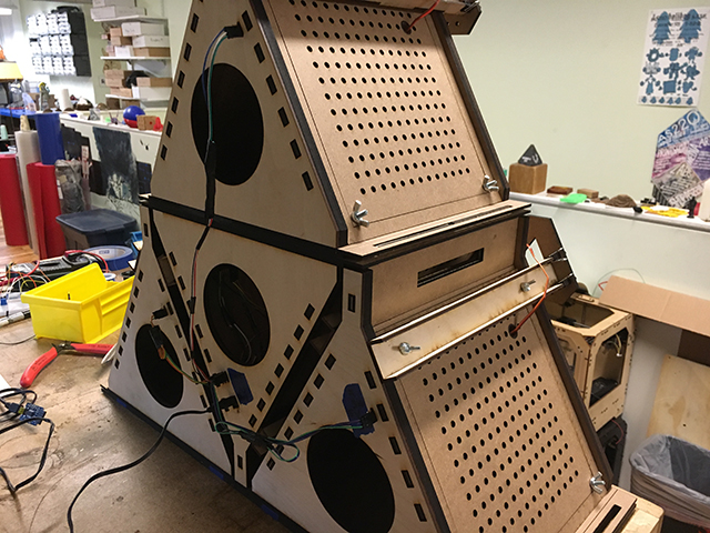
Once it is done, it can be attached to the whole structured made before. The final box with the arms and the servo indside the servo box attached looks like the image below. I made a total of 4 and they can join almost in any way with each other.
This is how it looks like when the 4 are joint together.
For the electronics, I made a SatshaKit board that behaves like an Arduino.
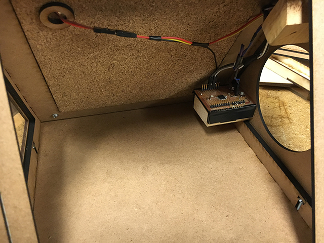
One of the boxes was going to behave like the one hosting all of the electronics so I thought it could be the middle one because the distance with cables from the boxes that were to the side would be minimzed. Also the middle box had a power adaptor to receive the power cables from all of the other boxes and then be plugged to the wall.The connections for the cabling look like this. Please note that these were made by hand with wooden pieces and some of the holes were cut with the laser cutter on already cut pieces.
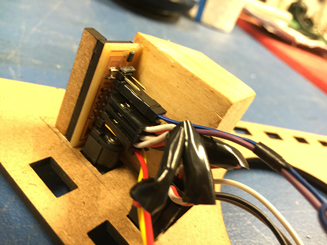
The cabling for the inside of the middle box was done like this. This connects power and ground from the SatshaKit board to the power and ground 5V pins of the powerboard. And it also connects pin 10 to a cable and power and ground 6V pins to a triplet cable that will later be connected to the servo motor connection.
Also within the same panel the power, ground and signal pins coming from the three other boxes are internally connected to the powerboard and to the other pins in the SatshaKit so that when the other boxes connect through a simple plug from the outside, it all works perfect in the inside.
Once I attached the electric panel to the box, it looked something like this. I connected the local motor through a hole I drilled manually around the upper left corner so that the motor's cables could come inside the machine through that spot. Inside the connections are quite clean and the only thing left to be done would be to to some simple inside connections in every box like the one seen here but to the three pins that go to the exterior of the box, and then make the connection from box to box.
This is how all the four boxes look connected through the back.
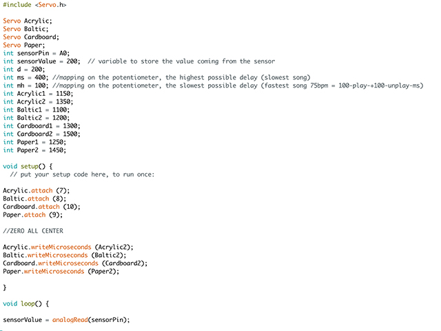
I programmed in Arduino the same way I had programmed the first motor I did for Output Devices. What changes here is that I have four Servos working at the same time and also that I can make rhythms when playing with the delays. You can download the Arduino file here so that you can see better what in the picture is shown. Also, if this is uploaded correctly to the SatshaKit using an FTDI cable, then the drums should start playing! It is important to power the powerboard with a 6V connection but greater than 1A because they drawy a little bit too much current when they work at the same time. 2A or more should work!
This is the first version of my drum machine, I plan to make newer versions in the future so that I can make them connect in a network and have them all working with the same BPM... happy music-making!!