4. Computer controlled cutting
This week I worked on defining my final project idea and started to getting used to the documentation process.
| This weeks design | |
|---|---|
| test press fit | f3d fusion |
| Logo Gronings wild | svg file |
| parametric design | f3d fusion |
| illustrator Curve | ai file |
Lasercutter and vinylcutter
At the Waag Amsterdam we have the acces to a BRM laser of 100 Watt. This machine can cut through material as wood and acrylic with a max thickness of 1 cm. The machine can not cut some materials because of the toxic released. They have a strict policy which materials can be used. The lasercutter is water cooled and has a air compressor to direct the laser to the surface. Further has it a built in filter which cleans the air. The air is subtract from the machine by a ventilator which direct the air to the filter storage. The workfield of the laser is 113 cm width and 153 cm deep. Optional you can open a lid on the front to use bigger material on the lasercutter. The buttons on the laser are indicated with 1,2 or 3. Always keep that sequence when operating the machine. The first is a key to turn to the right to connect the machine to the power. With the second press button you turn the software on. The third switch is for the air compressor so that air is coming out at the laserhead.

Lasercutter at Fablab Amsterdam
The machine operates with software (lasercut 5.3) that came with the machine. You import the files as a dxf and prepare the settings for the lasercutter. The software generates gcode of the file to operate the machine. Gcode is a often used code for computer controlled machines. The interface of the software is described in the assignment.
Checklist For lasercutter before starting a job. (software is explanined later) 1. Use the three buttons to switch power and start software on the machine.
-
place the board you want to cut.
-
Set the origin by using the arrows. In the menu you can decide to anchor the origin.
-
Adjust the laser till it has the correct distance to the place for good focus. 12 mm is the standard. You can adjust the head by unscrewing slightly
-
Close the lid of the machine.
-
Make a testrun to check the dimension of the job. MAKE SURE YOU SET THE JOBORIENTATION IN THE SOFTWARE TO THE LEFT RIGHT. The machine doesnot recognize the borders of the machine. When not paying attention you can destroy the machine.
-
Turn on the ventilator underneath the computer.
-
Press start and see how the job goes.
-
ALWAYS STAY AT THE MACHINE WHEN DOING A JOB. This in case of fire. There is always water present in case of fire. When this happens turn of the ventilator straight away.
-
After job is done leave the lid closed till all the smoke is gone.
-
Take of the lid and take your awesome design out of the machine
-
After a big job clean the lens and the mirror with alcohol.
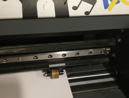
Further we have access to a vinylcutter. We have a roland gx-24 vinylcutter which is the most widespread brand for these type of machines. It has a width of 70 cm and the length depends on the roll which you insert. The cutting speed can go up to 500 mm per second. It have a simple interface to control the cutting. It works with a knife that moves on the x and y axis to make complex cuttings. Adding new vinyl to the machine is done manually. In the interface is a option to measure the dimensions of the roll so that the job will stay within the boundaries. A set origin is used to decide where the end is of the working field.
 The vinylcutter filled with test sticker you perform bvefore a job
This machine operates in the fablab Amsterdam on illustrator. You upload your vector file in illustrator and send it to the machine by using the print option.
Parametric design
For this weeks assignment we have to learn and incorporate parametric design. This way of designing give a good control of your design and enable you to make changes where the whole model adjust accordantly. Fusion 360 have features in the software, where you can change all settings of the design by adjusting one part. Lets assume you want to make a design for the lasercutter and you want to cut out the part on a 2 mm material. Your whole design is made to work on 2 mm material. When you want to get started lasercutting the design you realize the design needs more strength and you have to use 3mm thickness material. Without parametric design you have to go back to the drawing board and alter all changes to make it work. Thanks to parametric design you can just adjust the thickness and the whole design change accordantly. This is the power of parametric design. Before i got started on the weekly assignment i start looking at some tutorials of parametric design. I found the page of autodesk very helpful.
Autodesk parametric explanation
Testing Size slot test
In the lecture about Computer controlled cutting They explained the possibilities and limitations of the lasercutter and vynilcutter. One part of the assignment was to calculate the curve of the lasercutter. The lasercutter cuts out material with the use of the laser. The laser beam has a thickness which becomes important to know when precision of the design is important. When you make more parts which have to press fit in each other you have to know the curve. The curve also varies with speed, power and material.
Group assignment
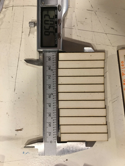
Together with Josephus and Mick we designed and executed the calculation of the curvature. To be able to measure the curve we designed 10 rectangles. The curve of a lasercutter is very smal and hard to measure. By creating ten rectangles the curve become good visible and good to measure. The design was made in illustrator by Mick. At first we had some discussions in how to execute the assignment. We thought it would be easy to go for ten rectangles of 1 cm width for each one with the total of 10 cm.
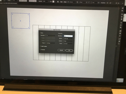
This we did by using the split in grid tool in illustrator.
object: path; split into grid. columns: 10
At first we used rectangles with this tool but that resulted in double lines which would affect our test. The laser would pass each line twice. We redid the grit tool by using lines. This gave a better result. We added a square around the object and a line for indicating the millimeters. All 10 squares together made a length of 10 cm. Now we had this done we safed the file as .dxf to export the file to the software(lasercutter 5.3) of the lasercutter. The lasercutter is not connected to the internet so we made use of a usb stick to export the file. First we safed the file on the computer and opened the software to import our file. You should use import instead of open file. By using the resize option on the left side we resized the file to the correct dimension. Somehow dxf files sometimes resize the image so always check if the dimensions are correct. Next step is to place the object in the centre table so it is in the workfield of the lasercutter. Edit –> Centre table.
 placing object in centre.
With the colors on the bottom of the screen we selected the curve lines by choosing a color so the machine understands this has to be cut first. The mm indicator we gave a separate color to be the second cut and the surrounding boxes were the last cut. On the right side you can change the speed and power settings and arrange the order of the colors. settings first test
cutting: power 100, speed 30: mm indicator: power 30, speed 100
 See something strange? Count the lines. Thought we deszigned 10 boxes
After we put all the settings in the software we safed the file on the computer as a .eps directory. Next step is to prepare the laser cutter. To put the lasercutter on you have to use one key and two buttoms indicated with 1,2,3. Always use this order.

Then we placed the poplar triplex on the grid of the machine. By using the 4 arrows you can navigate the laser to the starting point. to have the correct distance between the laser and the object we use a wooden indicator to get the correct distance. by unscrewing the laser where the brown cable stops you can adjust the laser head to the right distance. see image
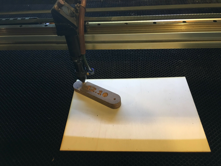
adjusting the distance
On the panel you now can achor the point by clicking the bottom and press enter. When this is all sett you close the cap go back to the software. By pressing download on the right bottom side of the screen you can upload the file to the lasercutter. then a screen will open. Always press delete all files. Then press download current. Now the design should be exported to the lasercutter. You can verify this by pressing file. Then the name of your file should pop up. Next step is to verify the outlines of your file. This is important to see if the triplex is placed correctly. This you can do by pressing test. Now the laser head m,oves around the working field. Almost ready to laser your work. One last VERY important step to take. Turn on the ventilator. Never lasercut without the ventilator on. You can put this on with the button underneath the computer.
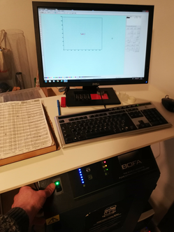
light should be green before the start of the job
When everthing is ready you can press the green button (start) and the laser starts cutting. Always stay present at the lasercutter in case of unexpected events like fire. On the lasdercutter there is a waterspray bottle in case of fire. When there is fire quickly press the ventilator of and spray with water. After the job is done leave the lit close for a minute before opening.
In total we cut out the test four times with different setting to check if this would effect the curve.
| poplar wood 3mm: | ||
|---|---|---|
| Speed | 30 | Power |
| Speed | 15 | Power |
| Speed | 30 | Power |
| Speed | 15 | Power |
| Hard Wood 3 mmn: | ||
|---|---|---|
| Speed | 15 | Power |
| Speed | 30 | Power |
 result cutting test
Now the tests were done we could start calculating the curve by measuring the 10 pieces. In this stage we realized we made a mistake earlier when designing the ten squares. We we counted the pieces it turned out we had eleven pieces. Somehow we all did not realize our mistake till all parts were lasercut. The mistake was made when we start using lines instead of rectangles. We added ten lines between the two endlines which result in 12 lines total and 11 rectangles This does not effect the the test of the curve. We just had to divide the total by one more. In the proces of calculating the data we discussed who we could best calculate the curve. We first measured the 11 rectangles and that number we substracted of ten. The outcome we wanted to divide by the amount of lines. Josephus came with a good insight, with this way of measuring we should count the 2 outside lines as one. The surrounding box got enlarged by the curve aswell and that we should incorporate in the calculation.
10cm - measurement 11 rectangles / amount of lines - one / ofset both ways (2)
Results:
| poplar wood 3mm: | ||||||
|---|---|---|---|---|---|---|
| total | size rectangles | result | lines-1 | curve | Devide by both sides | ofset |
| Speed: 30 | Power 50 | |||||
| 100 mm | 96.96mm | 3.04 | 11 | 0.276 | 2 | 0.138 |
| Speed: 15 | Power 100 | |||||
| 100 mm | 97.25mm | 2.48 | 11 | 0.225 | 2 | 0.112 |
| Speed: 30 | Power 100 | |||||
| 100 mm | 97.25mm | 2.75 | 11 | 0.25 | 2 | 0.125 |
| Speed: 15 | Power 100 | |||||
| 100 mm | 95.03mm | 4.97 | 11 | 0.451 | 2 | 0.225 |
| poplar wood 3mm: | ||||||
|---|---|---|---|---|---|---|
| total | size rectangles | result | lines-1 | curve | Devide by both sides | ofset |
| Speed: 15 | Power 100 | |||||
| 100 mm | 96.34mm | 3.66 | 11 | 0.332 | 2 | 0.166 |
| Speed: 30 | Power 100 | |||||
| 100 mm | 98.72mm | 1.28 | 11 | 0.116 | 2 | 0.058 |
The results are interesting to see. The speed and power have influence on the curvature of the laser. Also the curve is different depending on the type of material. This made me realize the importance of calculating the ofset with different materials. Especially when dimensions are important to the design or when you want to create a press fit design.
Looking back on calculating the curve we could have calculate it in different ways. We could have measured the gap that was created by the curve with 11 rectangles. This method would include the outside lines. Another method we could have used was to measure the individual rectangles.
My team mates Mick and Josephus
Testing pressfit Carton
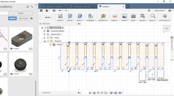
For the weekly assignment we have to make a press fit construction in carton. To test what size i should make the connections i made a simple test case to see when the carton fits well in the joints. In fusion 360 sketchmode i made a simple design for the test. I made several simple joints with a few milimeter differents.

test case starting at 2.5mm to 3.25mm
I tried to export the file in dxf extension to the lasercutter. The software (lasercutter 5.3) did not recognize the dxf file. So i opened the file in inkscape and safed it there as a dxf file. I tried a few different setting but the software recognize the dxf file best with unclicking ROBO Master type.

unmarking box for exporting dxf
I lasercutted the object two times so i could test the press fit. I cut the design in carton with speed 100 and power 50. Now i was able to check when the fit between the joints was strong. In my test the carton fitted well into each other with 2.5mm gaps.

strong joint connection carton
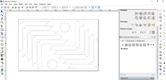
The vinyl cutter
For this assignment i decided to make a sticker of my company logo. I looked for my design file but was not able to find the inkscape file anymore. I could find a logo image and imported this picture in inkscape. The vinyl cutter need to work with vector files to be able to recognize the path it needs to take. By importing it in inkscape i wanted to create a vector file. I used the trace bitmap option in the path section to create nodes on the different paths. My logo consist of only strokes so it was fairly easy to convert. My first cut with the final cutter failed however. The lines of the converted image were not coherent. There were places with double lines and the design was not a suitable vector file.
With still my logo in mind i decided to create a new layer to trace the lines and make the design better fitting to cut out as a sticker. I enlarged the spaces between the lines for a better result. Now i was ready for a new try. The computer connected to the vinyl cutter run on linux and on windows. During starting mode i could choose the operating system by pressing f2 and to have acces to the machine i logged in windows. Here i could open my file with illustrator.
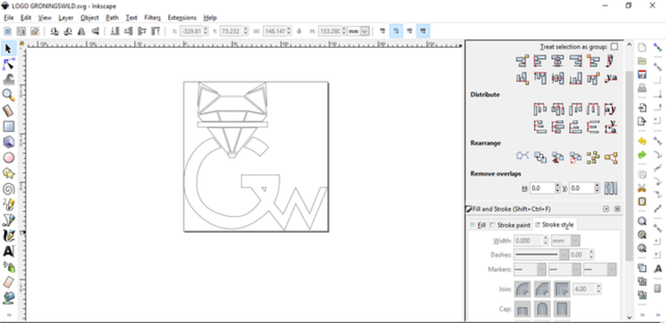
Logo Gronings Wild
In illustrator you can adjust your file. The file now was correct and i checked if the lines were 1 point wide. When the lines are wider then one point the vinyl cutter will cut on both sides of the line. This can be used in certain circumstances but i just needed a clean cut. Next step is to check the print settings. The machine is simple to use and by just sending the file to the printer by selecting print the machine will start cutting. In the settings i wanted to check the position and the speed of the machine
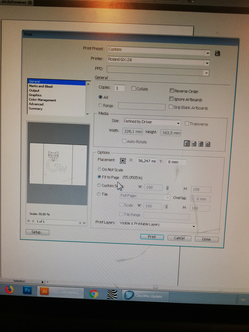
settings menu
For the placement i went for the bottom left. That wil be the indication for the machine to start from. Further i choose for the do not scale option since the vector drawing was already the desired size. The speed setting you can adjust in printer preferences in settings. I decided to go for the default option.
Now it was time to prepare the machine. First is to select the vinyl you like to use. I am planning to use it on a black background and choose for white to have good contrast. The roll you place on the back side with the sticker side on top.
insert roll in machine
The rollers i adjusted to the end of the vinyl. This you change at the back of the machine. The rollers have to be on a white indicated place as you can see on the picture. Then you can press the rollers tight by the handle on the left back side of the machine.
First i you need to know what pressure (force) of the knife is most suitable for the type of material. You want it to cut trough the first layer and keep the bottom layer intact. This can be checked by doing a simple test. First position the cutter where you want to make a cut. Then by keep pressing origin till you see on the display its positioned, you place the knife on the desired place of the work field. If you then keep pressing the test botton the machine does a small test with a square in a circle.
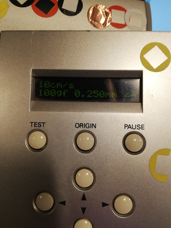
Display vinyl cutter
The force setting of the knife was on 40gf when i did the test. This you can change in the menu of the machine. The test came out nice. I checked the back if the knife did not get through te viyl and i checked how easy it was to remove the sticker. Now i was ready to cut out my logo. I put the origin on the right place and pressed print in illustrator. The machine started cutting straight away.
To remove the vinyl you use the same handle for thigh ting the rollers. I cut the vinyl of with a knife and started removing the vinyl i did not need. I slowly peeled of the vinyl and held the parts that needed to stay with a knife on its place. When all excess maerial was removed i used a transparent roll to transfer the sticker. I made sure the the tranfer sticker was placed smooth of the logo. Then i removed the backside. Again this need to be done very careful.
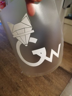
Ready to use
I placed the sticker on the backside of my laptop. First i clean the backside of the laptop to assure the sticker stays put I made sure i put the sticker on without bubbles. With my hand i pressed the sticker on all places so it was tight before removing the tranfer sticker. Again remove this very gentle. Here the final result.
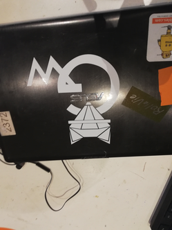
logo on laptop
Parametric design and constraints, constraints issues, constraints errors..
I have been designing using fusion 360 mostly in the model and sculpting mode. The sketch environment i used mostly to quickly create 3d models to continue to work on in the 3d environment. Excact dimensions and scaling option were so far not important in my designing. I liked the challenge of designing a parametric model using constraints. After watching some tutorials to grasp the notion i thought it would be simple to archive. I was so wrong.
In building press fit parts using constraint and parameters i was playing around in what is the most efficient way of setting constraints. My first try resulted in a design overcomplicated with constraint. When trying to adjust certain features i gave me constraint issues. one issue i tried to tackle was making a circle with slots in the centre. To do so i made a circle and placed ramdom squares around it for the slots. I had some issues first to centre the squares with the circle. After some failed attempts i found a way that seems to work. I use the symmetry tool and first select the two lines and then the line i want to be symmetric on. I realized the importance of parametric designing and decided to put my energy in understanding and using constraints and parameters instead of making a ecstatic design for this weekly assigment. Realizing that in the weeks to come i have to get accustomed to this way of designing so i have to learn to work in a efficient way using parameters.
First i wanted to discover how you can repeat a constrained design using the circular pattern. Finding a way to to set constrains and repeating them would safe time in the long run. I decided to make the parameters thickness and diameter to make it possible to scale this object. With constraints i locked the positions till the design was fully constraint. The slots i made even using the equal constraint. For the depth of the slot i added the dimension thicknes X 3, This way the depth wil always be three times the thickness. I decided 10 make ten slot by using the circular pattern tool.
360/10=36/2=18
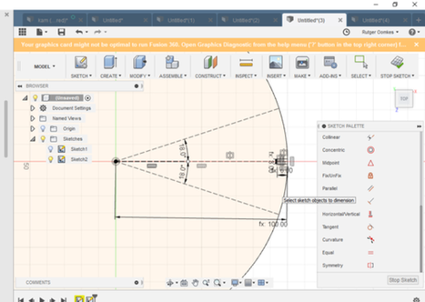
Making constraints to pattern
I made two construction lines with the a angle of 18 degree from the centre. Then by using the trimming tool i removed the rest of the circle.

Using the circular pattern tool
With the cicular pattern tool i copied the orginal 10 time around the centre. Now i had a fully constraint circle which you can set the dimensions by using the two parameters i gave them. Next step was to create a arc with several slot to make a press fit cicrle which you can connect in multiple ways. Here the real trouble started. I though this would be a five minute design. But i did everything wrong in trying to constrain the arc. First i placed to much constraints when starting of designing, when i changed something it resulted in constrain issues. Further i placed constraints in the wrong places, so when changing parameters the object changed not as hoped. In effort to solve the issue i used more parameters making the designs way to complicated. Also i tried using construction lines without much succes
 Made a total mesh of the workfield

Parameter menu
After spending way to much time on constraining the arc i decided to first take a step back and make a more rectangular shape. I found this easier to constrain. With this kind of shape you can fix angles and corners and took me a short while to constrain the rectangle arc.

rectangular arc
Most tricky in constraining this was the inside 45 degree line between horizontal en vertical axis. The design was fully constrained but when i enlarged the design the inside disappeared and the design got a different shape. First i made a dimension on the outside line length/3
when i switched this to the inside line with the same dimension the shape stayed intact when changing parameters.
Now the two shapes were created i tested the parameters to check everything was set up for the print i encountered a problem in the circle. I did not seem to change the thickness and the slot depth. When i tried before it seemed to be working. I redesigned the circle but this time i let the circle intact while copy the slot with constraints around the circle with the circular command. Now finally the design is ready to laser cut.
Circle parameters:
Diameter:       75 mm
thickness:       2.45 mm
slot depth:      9 mm

rectangular arc parameters:
Rechthoek length: 200 mm
Rechthoek thickness: 30 mm
thickness:      2.45 mm
slot depth:     9 mm
I exported the two sketches separate as a dxf file and opened the file in inkscape. Since the lasercutter somehow does not recognize the dxf file from Fusion 360 i safed as a dxf on inkscape. I did had to remove the construction lines.
When cutting out the pieces it turned out not so press fit after all. The carton board was slightly smaller then anticipated. The test i did before indicated that 2.45 mm would be a press fit connection. I redid the test with different sizes slots and came out on 2.25 to make a proper pressfit for this carton. After doing this i changed the parameters and cut out the pieces again with setting power 50, speed 100. Still it did not was pressfit. Looking at my fusion 360 file i realized what went wrong, In my design the slots of the circle were not completely parallel to each other. After fixing this by adding the parallel constraint to the design the design was finally press fit tight. Made two different objects from the design.

Redo test with carton
Final result
 Final result press fit
Some links of useful tutorials about parametric design https://www.youtube.com/watch?v=qO6QpUKP6PY&index=4&list=PLKGSPaubfwgVmxxs_N6RWKAUOyOiQ-X-2&t=0s https://www.youtube.com/watch?v=PwVRaWxW7F0&list=PLKGSPaubfwgVmxxs_N6RWKAUOyOiQ-X-2&index=2 https://www.youtube.com/watch?v=-rm_vtKcpnA&t=0s&index=2&list=PLKGSPaubfwgVDXhPHoQE-8P41n2_2tsz3 https://www.youtube.com/watch?v=J_2If5zVp84&t=2s
What i learned and what went wrong.
This weeks assignment was great to understand and see the importance of constraints in design drawing. For precision lasercutting it is important to realize the curve of the laser cutter. This will result in more exact results which is important when designing multiple objects that need to fit perfect in each other. What went wrong that i underestimated the difficulty of putting restraints in a design. It took me way much longer to make sketches complete constrained. I wanted to make a much more complicated design but got stuck in the process and downscaled my expectations. I would still like to create something more beautiful and complex. Will post this in this weeks assignment when updated.