3. Computer Aided design
For this weeks assignment we started modeling the final project and show the work in as many different way, like animation, sketches, animation, render, etc. I decided i would stick to the spiral development principle, where i work out fist a simple concept and improve the concept along the way. From last weeks assignment i realized the importance in good planning and documenting at the same time.
Thursday 31st of January we got a master class in designing in fusion 360. Which was very valuable. I have already knowledge in using fusion 360 for creating 3d models, most however i learned from tutorials on line. Luckily fusion 360 have a big online community and there are lots of tutorials to find. This masterclass by Mauro Jannone (fablab Rome) was very helpful in teaching how to work in a organized way. He covered allot of different facets of the fusion 360 environment. Aspect what were particular interesting where parametric design, The patch environment, Assemble parts and creating joints, projecting parts on a different axis and use of patterns.
| This weeks design | |
|---|---|
| File of the fablab nodes lamp | f3d fusion |
| inscape file of nodeslamp | svg inkscape |
| Files from unity | Unity File |
| animation unity | unity animation mp4 |
| Gimp | xcf gimp |
Fusion 360: Designing the final assignment
When i started of designing the final assignment in fusion 360 the idea of the design was mostly in my head. There are many ways to get to the final design but time wise i wanted to make it as efficient as i could. Therefor i had to tackle some design issues. For the fablab nodeslamp i had a sphere in mind where the different fablabs where pointed out from. A sphere is a hard object to work from. A flat surface alowe you to sketch on and continue the design. With a sphere you have no surface you can work from. This was my first priority to tackle. I came up with different solutions.
-
Making a object on a plane away from the centre and change the pivot point to the centre point. By using the copy option multiply the object around the centre creating a circle. By selecting them all an redo the copy option making from the circle the sphere. After a first try i quickly gave up on this. I took simple way to long to achieve the desired result.
-
Using circular pattern. Create a cirle and calculate how many lines would fit in 360. i decided to go for 24 lines in total. After doing this i extracted the object and performed a pattern circulair. Now i chose 12, since this would close down the cirle. Next i downloaded a mesh from the earth and resized thil it fitted in the object. To be able to see the earth i change the material of the object in to glass. Next step is to find the locations of the participating fablab and mark them with point.
 circulair pattern
 Multiply the object creating a circle
 Render of work in proces globe
Inkscape: Preparing the map
In the process of making the lamp design i changed my mind in how the lamp should look, for practical reasons and for visual experience. The problem with using a sphere is that not all locations will be visible from one angle. Another reason for the shifting design is that the new design can be placed from the ceiling but can also be used on a wall. i tried to simplify my design by using inkscape to identify a image of the fablabs around the world. I imported the png image of the worldmap and by using the trace bitmap to make it a adjustable file with nodes i can adjust. For this purpose i choose to do multiple scan resulting in several usable vector images to work with. i got the map from https://fabacademy.org/nodes/

Earlier i tried to use a detailed worldmap with this method and turned out way to many nodes in the file to work with in Fusion 360. This map was way less detailed and more usable to work with in fusion 360. i putt fill on nothing and the stroke on black. I left the nodes from the different fablabs on the map so i could pinpoint them later in the design on a easy way.
Now i could import the svg in fusion 360. i made some lines to be able to break up the different continents. Then i extruded the continents into 3d objects. I moved and turned the continent till i found it looked nice.
 *Extruding and turning world map
*
on the backside i sketched lines to connect the different continents, by using the pipe command i transformed the lines into solid pipes all ending up in one point which will connect the lamp to a wall or ceiling. The nodes i wanted to point out on the map using a pin, these will show the activity from the different fablabs. I could easy copy the pins around the map using the move command point to point. Since i still had the places marked out i could place them simple on existing points. When all pins where on the location i filled the original holes by extracting them the same distance as i did with the map.
*Extruding and turning world map
*
on the backside i sketched lines to connect the different continents, by using the pipe command i transformed the lines into solid pipes all ending up in one point which will connect the lamp to a wall or ceiling. The nodes i wanted to point out on the map using a pin, these will show the activity from the different fablabs. I could easy copy the pins around the map using the move command point to point. Since i still had the places marked out i could place them simple on existing points. When all pins where on the location i filled the original holes by extracting them the same distance as i did with the map.
 selecting and copy the nodes
When everything was on place i went to the render menu to give colors to the different points by using the appearance command. The pins i colored green, yellow, red and blue using translucent plastic. The world map i colored glass frosted light. Which i most likely would use in the real version but then in acrylic. I Would like to see the whole map lighten up in my final design in white light and the pins depending on the status of the different fablabs. Here two pictures of the final design using the render in fusion 360
 sideview lamp on wall
 downview lamp on ceiling
Link to [fusionwebsite 3d simutation]https://a360.co/2Soarkj
Most of my time this week i have been working on the design and understanding new techniques in fusion 360 after the masterclass on thursday. Further i have working on fixing the returning issues concerning git and the terminal. After repeating errors in the ubuntu terminal i install a windows bash terminal to be able to push my work. In week 2 i explain the steps i did this week in changing the settings for a new workflow. The coming days i will explore the different existing programs for design and animations.
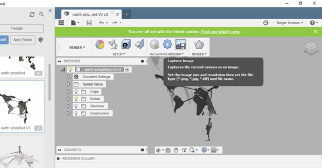
Exporting STL File from fusion 306
I am keen on learning more about the game engine Unity. A extremely powerful tool to create animations or games. My personal interest in learning the software is to create a animated video of designs i make. This software enable a designer to show there work in a self created world. I have not used software like unity before. i watch some tutorials and decided i would download the program to create a animation of my final project. I choose for the free (limited version) for students. i learned from the tutorials i could upload a object in the program when it is a obj file. Strangely enough i could not export a object file from fusion 360. Instead i exported the file as a stl file and safed the file on my computer. to do so i first had to combine the different objects in one single object by using the combine tool in fusion 360. In my fusion browser there was now 1 object. With a right click on the object i could export the object as a stl file to my computer.
Meshlab: Useful tool converting stl in obj files
In the past i imported mesh files in fusion 360. The problem with stl meshes are that the objects are made out of connecting triangles. Fusion 360 prefers to work with object files which are basically connecting squares (quads). At least when you want to use the sculpting mode in fusion 360. I found a program online i merely use to convert a stl mesh in quad dominated mesh, after which i import in my fusion interface. In this case i used the program to convert my final project stl mesh in a obj mesh.
 converting to quad dominant mesh
Unity: Game engine useful for creating animations
After doing this i exported the file as a obj file to my computer. Now i was ready to import the object in to the Unity workflow. To import your own object file in unity is fairly simple. In the Assets tab you can use the right click to import a new Asset. I selected the object file and loaded into the asset list.

To use the object you can drag the file in the scene. Then the object appeared in the scenery.
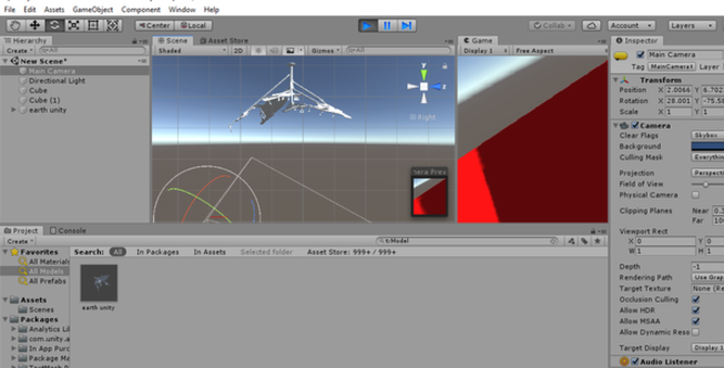
 To be able to make a animation i selected the object i wanted to use for the animation. In this case the Node lamp. I selected the animator. After that i went in the windows browser to select animation. The document that opened i dragged to my console at the bottom. I saved the file and saw a time line i could use to create a animation.
 I choose a startingpoint for the camera and object and pressed record. By draggin the timeline further changed the settings of the object. I repeated this step a few times till i had a animation of 15 seconds. I am new with this software and kept the surroundings simple to focus on the animation itself.
I used several tutorials to get used to the interface and workflow.
I choose a startingpoint for the camera and object and pressed record. By draggin the timeline further changed the settings of the object. I repeated this step a few times till i had a animation of 15 seconds. I am new with this software and kept the surroundings simple to focus on the animation itself.
I used several tutorials to get used to the interface and workflow.
https://www.youtube.com/watch?v=QUCEcAp3h28&t=309s Getting started with unity
https://www.youtube.com/watch?v=G4Ja-asl8hQ helpful for creating a animation
When i was content with the video i wanted to export my animation. Here i encountered a problem. There is now easy way of exporting your animation to a mp4 format. After some trouble seeking i could not find a good way of doing this. More research necessary. For now i recorded the video with my phone to show at least the result.
animation unity First attempted animation Unity
Gimp: Raster program used for images
For a good impression of the design i wanted the design shown as a picture in the fablab Waag. To do this i used Gimp 2.10.4. I have used this program before but only to prepare pictures to vector formats. I downloaded a old picture of the waag i could find on the internet.
This would be the background. The other picture was a down view picture of the lamp. In fusion you can capture a image in the render menu.
I realized the moment i tried to import the picture in Gimp that it automatically remove the background, which made i much easier to combine the two pictures together. First i made the mistake to upload the lamp first in Gimp. This decides the size of the workspace. It is better to first upload the background and then the attribute you want to blend in. I imported the pictures by opening them as layers.

I resize the lamp to the proportions i like to see and dragged the picture in the right position. I exported the file as a jpg file. In the terminal i used image magick to convert the file to png and reduce the qualilty to 80%
$ magick lampinwaag.jpg -quality 80% lampinwaag.png
 Image of the Waag Amsterdam with Fablab Node lamp on ceiling.
What i learned and what went wrong.
For this week assignment i am happy i put my focus first on designing the final project instead of focusing on other existing software. After i designed the lamp i could use this file to create pictures, render and make animations of the object using other alternative software. Futher i am glad that the concept changed while designing. This design seems more realistic to achieve and easier to alter when the nodes change. Also i am pleased with the change of terminal and reinstalling git. Especially since for this weeks assignment i had to upload lots of files and images this new set up resulted in less time spending on solving issues. Looking back at this week i can see point for improvement. In fusion 360 my focus was on quickly creating a final design which made a mesh of the time line. I tried to alter some thing in the design in a later stadium and it difficult because of my messy workflow. Also i wasted time in search of good tutorials for new software by not being specific about the question. What i enjoyed most was exploring the software Unity. Just touch the surface but i can see the potential.