Final Project Development
Orbital motion speaks to patterns above astronomy. People that comes and goes, events that occurs and reoccurs, past memories that get reiterated and remembered over and over, etc. Exploring the mirroring relationship between planetary movement, geometry and human relationships is at core of my current practice.
Orbit-in flux is a device that allows you to study changes at your desired pace. I am using a planetary gear system, with two small gears of the same size orbiting each other around the center gear, which is activated by a stepper motor. The potentiometer can control how fast the stepper motor moves. The structure is divided into three parts, gear platform, led and zoom lens mounting panels and the shell. Parts that use wood are the ones that expects more drilling and changes to the material state after laser cutting, since acrylic cracks easily with reworking. Laser-cut modules are attached onto two gears. This system allows me to customize any shape I need with the laser cutter. The state of a circle is reshapd every second, the amount of color that is seen in the screen shifts constantly.These fluxes speak metaphorically to human relationships in every day life, which is what interests me in my explorations.

Idea Development
There was another PROJECT that I was working on earlier. After finalizing the dimension of the structure, however, I had some worries for my work and lost motivations. First of all, I didn't want to make a big work. I will need a space to store the work, and moreover, the space requirement for showing the work is really specific. Secondly, the work felt too much an illustration of a romanticized state of mind. I had too much expectation for my audience to interact but and the way I tried to stimulate interaction doesn't feel spontaneous enough. I took sometime to jog down key ideas in my previous project, and cross out ideas that I thought was etravagent or irrelavent for me to eplore at the moment.


This more controlled brainstorm session helped me to narrow down my interest to light, projection and orbital motion. On the side, I was reading Josef Albers’s Interaction of Color to re-educate myself painting and revisiting works of Moholy Nagy. Interestingly, both are artists and teachers (both painters as well) from the Bauhaus school.
Moholy Nagy was interested in the interaction between art and technology. ''Technology advancement'' speaks to increased productivity, which accelerates the speed in which we encounter objects. Art becomes the space that allows those constant changes themselves to be framed in a given setting. I find his Light Space Modulator really relevant to the present - how it shows the fluxes of urban encounter in the context of post-industrialization. Moholy Nagy attempts to remove as much romanticism from his practice as possible. The constant changing impression of light and faces of the rotating objects, nevertheless, speak continuously to metropolitan experiences 100 years later (it's 100 years anniversary of Bauhaus!!).

Josef Albers believes color is never seen as it physically is. To learn color effectively, one needs to develop an eye to recognize color interaction, instead of merely learning color theory. Josef Albers wrote in the introduction of his book that the search for interaction of color ''will lead from a visual realization of the interaction […] to an awareness of the interdependence of color with form and placement; with quantity (which measures amount., respectively extension and/or number, including recurrence); with quantity (intensity of light and/or hue); and with pronouncement (by separating or connecting boundaries)''. I realized recently, as a painter, that my interest in color lies mostly in light interaction.


Goal
I will make a modulator to study color interaction based on light. All designs will be modular, which allows my to disassemble and reassemble the modulator easily. The props are also modular designs. They can be attached to the surface of the gears. As long as I have access to a laser cutter, new props can be cut immediately and be attached to the gears.


Here is a diagram that illustrates my initial idea for the components that goes into the projection.

Expectations:
1. Modules are attached onto planetary gears and able to perform orbital movements.
2. LED light provides enough lumens for projection.
3. The structure embeds gears, led, electronics and projection unit as a whole.
4. Switch buttons for LED and Stepper Motor; potentiometer for stepper motor.
5. All designs are modular; parts can be easily redesigned/added/assembled/disassembled when necessary.
Planned Workflow
Based on my concept and expectations, here are the parts that need to be designed:
Structure: gear, light source holder, lens holder, modulars that orbits on the gear, exterior shell
Electronics design:LED, stepper shield, stepper shield pot, switches
Final Stage:wire packaging, assembly
I estimate that the structure would take the most time. Although there are several electronic design component, but the code and the mechanism are simple.
I also aim to finish all the components ahead of June 19th, so that I can spend time on adding more components if needed as I assemble all the parts together.
It is difficult be know which part to design first, but here is my planned workflow:
1. structure/gear design and gear platform: after this stage, can do tests with stepper motor
2. electronics/stepper motor shield
3. electronics/led: do a test on breadboard to make sure enough lumens for projection then finalized the pcb design and make the led board
4. structure/shell prototype: make cardboard prototype with existing components to visualize the projection; after this stage, I can finalize the dimension for the shell design
5. electronics/finalize the switches and pot that are used in the project
6. structure/shell design
7. structure/gear modular design
8. final stage/assemble the structure except for the top
9. final stage/wire packaging design: embed all the wires into the shell neatly; design wire package
10. final stage/finish assembling the structure
11. final stage/documentation
Bill of Material
Gear and Structure Design
5mm black acrylic (650*450mm) x4
3mm black acrylic (350mm *100mm) x1
3mm translucent acrylic (450*450mm) x1
3mm transparent acrylic (450*450mm) x1
2mm transparent acrylic (650*450mm) x1
5mm wood (650*450mm) x1
3mm wood (650*450mm) x4
4mm 3d print PLA filament
M2 bolt and nut for mounting gear host, 15mm x4
M2 bolt and nut for mounting stepper motor host, 12mm x4
M2 screw for mounting stepper motor host, 8mm x4
Electronics Design
Copper plate for PCB x1
Stepper Motor x1
Superbright LED 5W x1
A4988 Stepper Shield x1
Male pin header x21
Female pin header x16
Capacitor 100uF x1
12V male x1
12V 1~3A power x1
Aigo 5V Powerbank with two current output (1A, 2.1A) x1
Arduino, or you can download the schematics of siyUno from Input Device week to make an Arduino-equivalent board
Switch button x2
Potentiometer x1
Potentiometer Cap x1
Jumper wires x as many as needed
Solder iron x as many as needed
Components
4mm 3d print PLA filament
Assembling
3mm color acrylic x any amount of size you want depending on the amount of modules you are cutting
M3 bolt and nut for power unit, 20mm x4
M3 bolt and nut for mounting screen, 15mm x6
M6 bolt and nut, for screen 15mm x4
M6 bolt and nut for zoom lens-mount, LED mount and power unit, 10mm x10
4mm 3d print PLA filament
Paper clips for fixing long wires x use when needed
Gear Design
To generate the type of gear movement I want, I will be using the planetary gear system. I do want the ''planet gears'' to orbit around the center, forming an orbital motion with the two gear never meeting but supporting the orbit. This idea is conceptually interesting to me, and easier to design too than the orrery gear I figured out two months ago. Gear design is difficult, since a bit of miscalculation in teeth ratio leads to stuck gears. I used the formular R = 2 × P + S to find the ratio between number of teeth in ring gear (R), Number of teeth in sun (D) and Number of teeth in planet gears (P). Thanks to the Gear Generator site, I was able to insert the teeth sizes of the three gears.
First, this is the teeth ratio I got based on the formular:
8 teeth on small gears
30 teeth on center gear
46 teeth on external gear

Since geargenerator is not free, I was not able to save gears as dxf. I used the variables generated on the website and generated gears in FUSION 360 instead:


This is a view of the gears I laser cut in wood. More details on the structure hosting the gears can be found in the STRUCTURE DESIGN section:

The major problem I had with this system was I have to take the motor on and off the motor when making adjustments. While doing so, I can do damage to the center of the gear, making the motor gear loss and unable to stay in position. I decided to 3d print some parts that keeps the gear in the center:


This system worked better, however the part is too light to keep the gear in position. Taking the wooden gear in and out still damages the center. I decided, at the end, to 3d print the motor gear:


file: geardesign_motorgear.stl, planetary gears can be downloaded in the structure section
Gear system in orbital motion!!
Structure Design
In order to come up with the structure to host the projection, I have looked up many tutorials for homemade projectors. Although my goal is different, there are many things that can be learnt from existing projectors.
how to make a real projector: a really well made projector from wood that works like a bought projector
How to Make a Projector using bulb at Home: interesting slide projector
Make a slide projector using commonly available materials
There are several parts that were designed. Here was the master plan I came up with based on my research:

The 5W LED light is typically used in a torch, will would be enough light for my purpose. The led component comes with aspheric lens already, which generates a focused light. The light penetrates through a 4.05mm zoom lens, generating an enlarged light that penetrates through the transparent acrylic objects moving on the gear platform. A projection of the moving objects can be seen from the screen.
Gear platform
The gear platform is made of two parts, one is where the gear sits, another is where the gear system embed into the structure. Since I will need to adjust positions of many parts, I made the structure height adjustable, so that the height of the gear platform can be changed while assembly.
This is the first version of the gear platform:

I made the second version of the gear platform smaller, so that 1. I use less material for both the platform and the shell later:

file: gear_internalgearplatform_3mmplywood.ai
Mounting surfaces for led and zoom lens
These surfaces are designed as walls that can slide into the bottom shell, which simplifies position adjustment process.

file: internalmountingpanels_3mmplywood.ai
Exterior shell
I decided to use wood for the bottom of the structure, since I might be drilling a lot into the material when assembling. Acrylic has more risk to crack or break. The rest of the exterior shell will be acrylic, since I am looking for a material with a strong industrial and utilitarian look. All material will be 5mm thick.
My kerf test with wood/acrylic joins tell me a 4.5 wood cut fits into a 5mm acrylic sheet tight enough.


I’ve also left the front of the structure open for inserting a screen, which is a sheet of semi-transparent acrylic, the back of the structure open for inserting the power bank, PCB, and a hole for the 12 V cable at the back.


file: exteriorshell_5mmacrylicandwood.ai, powerandpcbunit.ai
Electronics Design
LED for Projection
There were several kinds of LED system I was thinking about to use:
Charlieplexing: a multi-plexing system that allows tag assigned to each LED individually. However, the LED board I made during output week was very dimmed down whenHIGH is assigned to every pin. On Neil’s board, I couldn’t find transistor for controlling the voltage and the current of the LEDs. Since Charliepleing uses digital pins as VCC and GND, I was not able to fSimple LED-plexing: igure out the connection from the transistor to the LED.
Simple LED-plexing: I tested the 5mm white LED, included a 2N2222 transistor to give the bulbs enough current. It did work, since all lights still kept its brightness. However, soon when I tried to project with this board, I do not get enough focused light. All light appeared as dots, even if I tried to put a aspheric lens in front of it.


Superbright LED 5W:A LED light typically used in a torch, as mentioned in the structure section, would be enough light for what I want to achieve. I bought this lightbulb from the electronic component mall on East Beijing Rd, Shanghai. When I powered the light from a power supply at 5V1A, already I got superbright result.


Stepper Motor
At first I wanted to use a DC motor. Since I am working with gears, however, I need a system that can control speed, which makes stepper motor a better option. I will need to add MOSFET to a DC motor to control its speed and direction. With a stepper motor, it only needs a stepper shield in order to cop with a micro controller, which I can program the amount of step the stepper motor moves in a given time easily.
The stepper motor shield I am using is A4988:
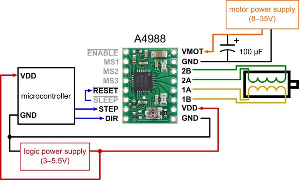
This shield is designed to fit onto an Arduino. In order to make it compatible to siyuNo, the Arduino-equivalent board I’ve designed during input week, I made a board that adapts the schematic of a Arduino and fit the shield :. I got the schematic of the board from Saverio. Then I made a PCB from this board for my needs.


file: stepper schematics,stepper board

An Attempt at Making Orbitno
I wanted to have both the LED and Stepper to power from the same power source, so that I can reduce the amount of wires in the design. Since the stepper motor requires 12V to run, the power source must be 12V. siyuNo, similar to an Arduino, runs on 3.3-5V 0.2A. The Superbright LED runs on 5V1A for the brightness I need. Therefore, I would need two voltage regulators.The voltage regulator I am using is L7805, which regulates any voltage a to 5V1.5A, which also works for the LED with 0.5A higher. I would also build my siyuNo into this board.


file: orbitno schematics,orbitno board
However, this system did not work with uploading program. I couldn’t burn boot loader. Strangely, Arduino gives an sck error command 1 sec after I click on upload, which never happened before. I tried fix soldering, connect it to a different computer, changing to a bootloaded ATMEGA328, using a different ISP, but all didn’t work. Even though the voltage conversion from 12V to 5V worked according to the multimeter, I was not able to use the board at the end. In order to proceed, I have to give up on this system.
Solution to Electronics
At the end, I decide to power the LED and siyuNo from a 5V power bank I already have. It has two USB connection, one with 1A and one with 2.1A. The stepper motor would be powered from 12V separately:

I made a LED board to connect the Superbright LED with the Power Bank and a Switch:


file: led schematics,led board

I also connected the Stepper Motor with a potentiometer to control its speed.
//Stepper Motor Speed Control with Potentiometer
//for Stepper Shield A4988
//Modified from Atmos iTech
//By Siyu Chen
//last updated: June 18, 2019

const int stepPin = 9;
const int dirPin = 8;
int customDelay,customDelayMapped; // Define variables

void setup() {
  pinMode(stepPin,OUTPUT);
  pinMode(dirPin,OUTPUT);

  digitalWrite(dirPin,HIGH); //Enables the motor to move in a particular direction
}
void loop() {

  customDelayMapped = speedUp();
  digitalWrite(stepPin, HIGH);
  delayMicroseconds(customDelayMapped);
  digitalWrite(stepPin, LOW);
  delayMicroseconds(customDelayMapped);
}

// Function for reading the Potentiometer
int speedUp() {
  int customDelay = analogRead(A0); // Reads the potentiometer
  int newCustom = map(customDelay, 0, 1023, 7500,12000); // Convrests the read values of the potentiometer from 0 to 1023 into desireded delay values (400 to 3500)
  return newCustom;
}
I tried to cut a part of the circuit in between vmot and voltage-in on my stepper shield, and use a jumper wire to connect a switch for turning the stepper motor on and off. However, this unabled the function of the stepper motor. The part circled in pink was where the circuit was cut.

Saverio suggested that the stepper shield I am using might have a built-in defencing function when it detects a short circuit. I will look into the datasheet more. However, I had to move on at this point from debugging this issue due to lack of time.
Components
I designed a lens mount for the 4.05 mm zoom lens I bought. It lays flat on the mounting panel when the lens is attached. The lens mount stays in place with four pairs of M6 bolt and nut.


file: lensholder.stl
Assembling
Since the structure is a modular design, it was quite easy to assemble. There were some parts I had to hammer, since the acrylic bends a bit under the heat of the laser cutter.
Base of shell and gear host:

Power unit:

Back shell and power unit:

LED unit:

Zoom lens unit:

Light test:

Screen test:

Modulars on the gear:

file:gearmodules.ai
Screen test after height adjustment of the gear host:
Evaluation
The process of working on this project has been a roller coaster journey. I began in the first weeks with different ideas, many that I will revisit in the future with my current knowledge in digital fabrication and electronics design. None of them was close to my final execution. I was very please that I settled onto a project that was even different from the project I began with in April. But through all these hectic processes, I truly felt content I have learned from fab academy is gradually transforming into expressive language for my art practice.
Evaluating Outcome Against Initial Plan
Modules are attached onto planetary gears and able to perform orbital movements. 90% complete. The gear system works well, however, the stepper motor makes a strong noise. It may has to do with the amount of current that is going into the motor through the stepper shield, which can be adjusted by turning the screw on the shield to different direction.
LED light provides enough lumens for projection. 100% complete. The movement and the object projects nicely onto the screen.
The structure embeds gears, led, electronics and projection unit as a whole. 100% complete. Structure is well designed, with all parts and wires packaged and embedded nicely.
Switch buttons for LED and Stepper Motor; potentiometer for steppermotor. 80% complete. Even with cutting the right part on the stepper shield board to connect the switch, I was not able to make the switch working with the stepper shield. I will need to read more into the stepper shield date sheet to see whether it has an embedded protection function for any short-circuit.
All designs are modular; parts can be easily redesigned/added/assembled/disassembled when necessary. 100% complete. While assembling, I realized I will need to redesign the top part of the exterior shell. The current design requires me to always open the shell when changing the modules on the gear. Furthermore, it is difficult to take off an acrylic piece that is deeply embedded into the joints without damage. Similar to the bottom of the shell, I will use wood for the top shell, with a piece of 2mm black acrylic to cover its surface. I will also design a door around the area of the gear, so that replacement of module will be easier.
Overall, this project has proved my hypothesis to be correct. I am pleased with the outcome, and looking forward to improve and design more modules for projection. I also want to keep exploring and design projecting structures at different scales in future projects.
Lessons I have Learned
Part of fab academy's expectation for the final project is to show time management and project development process. Although I tried to organized the development process by modular, the process itself is a lot less linear. Indeed, my project development followed an organic process with the structure design as the backbone of the project. Making a device that depends on the visual outcome of light projection and stepper motor movement, it was very difficult to settle on one set of measurement. I had to divided the structure design into many stages, and work in relation to electronic design. I realized I adapts to an organic working process well if I made a detailed linear workflow plan beforehand. I also learned that I have to be patient when one modular is not working. Sometimes moving to another modular and move back to the failure resolves the problem.
In a technical aspect, I also understood modular design, gear design, motors, voltage regulation, led a lot better. I benefit immensely from designing every part of the project in modular. When one part has an issue, it can always be easily removed from the big structure, redesigned and replaced.