4. Computer controlled cutting#
group assignment#
characterize your lasercutter, making test part(s) that vary cutting settings and dimensions**
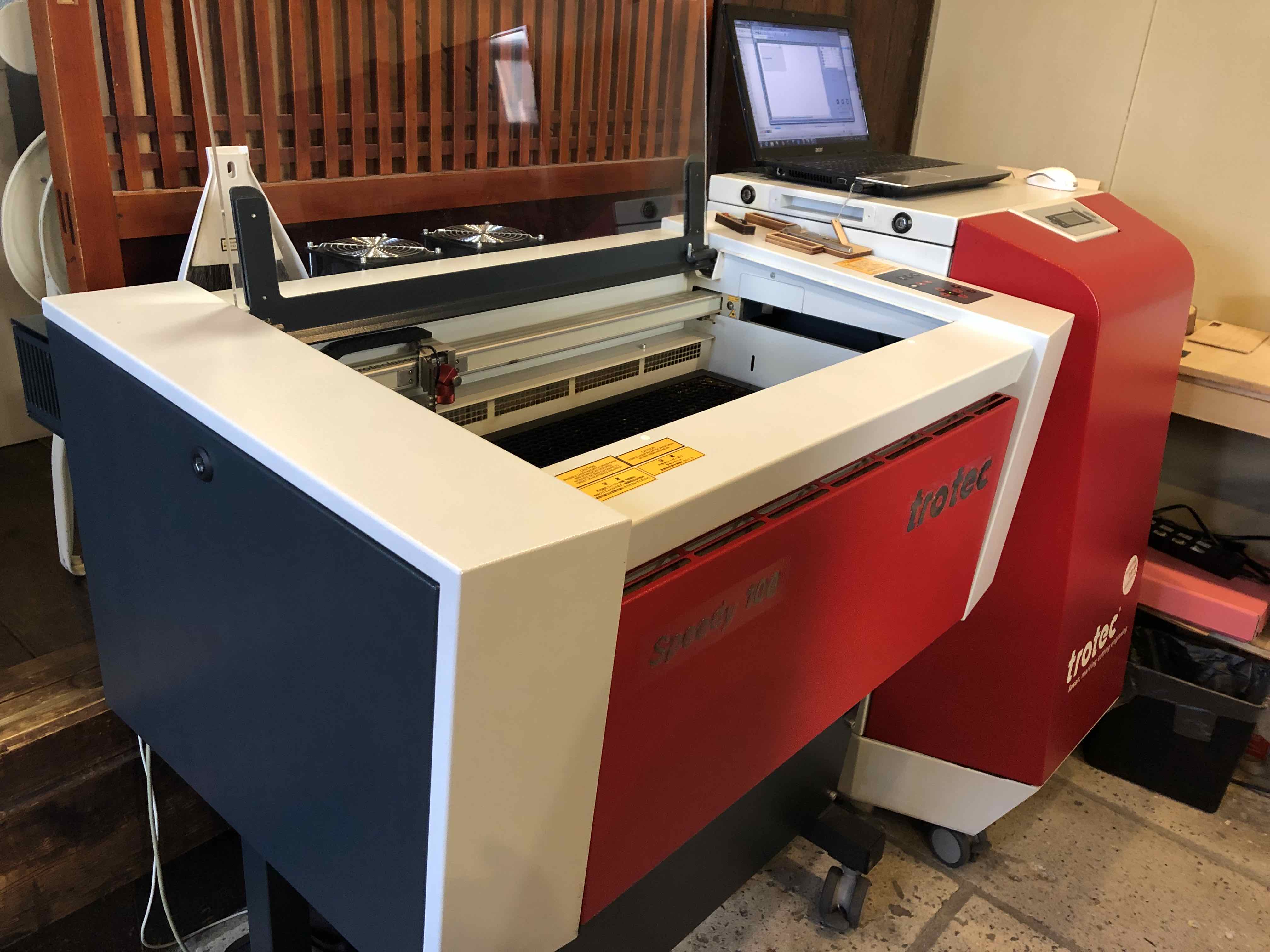
Fablab Kamakura’s laser cutting tool#
Model: Trotec Speedy 100, 30watt CO2 laser cutter
Each Member’s Group Assignment Tasks#
- Hiroya & Yosuke (Team A) identify optimal power and speed for cutting 3mm cardboard, then press-fit test for 3mm cardboard.
- Kae & Rico, the Saturday group (or Team B) repeated to the Laser Cutter power and speed setting testing as well as produced a Press-fit test strip (The Comb).
Team A: Identify Optimal power and press-fit test#
Optimal power and speed (Hiroya)#
We find the parameters that cardboard is just cut and just sculptures.
◯ First try with the roughly data#
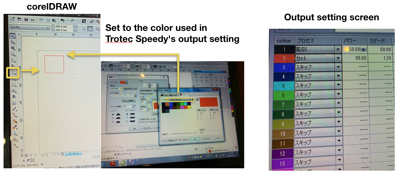
- Create a rectangle with corelDRAW which was installed on PC connected with Laser Cutter.
※The thickness of the line shall be less than 0.0003 pt
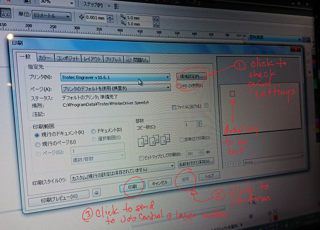
- file > print > Select “Trotec Speedy” > Print
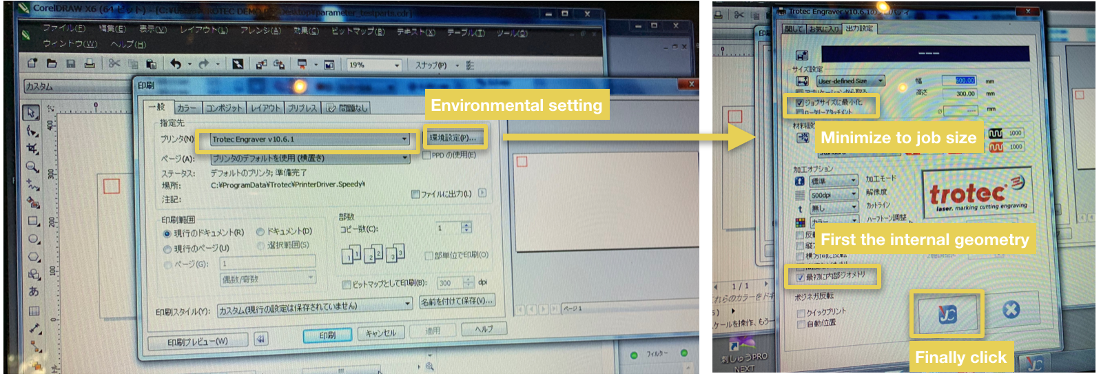
- ・Minimize to job size
- Output only the part to be printed, not the whole artboard
- ・First the internal geometry
- By processing from the inside, it prevents the material from shifting
◯ Setting up trotec Speedy 100#
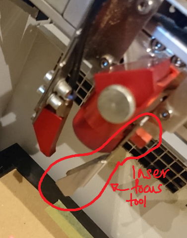
- Focusing lazer
Attach the jig to the side of the laser head. The moment the jig touched the material and dropped, the focal point.
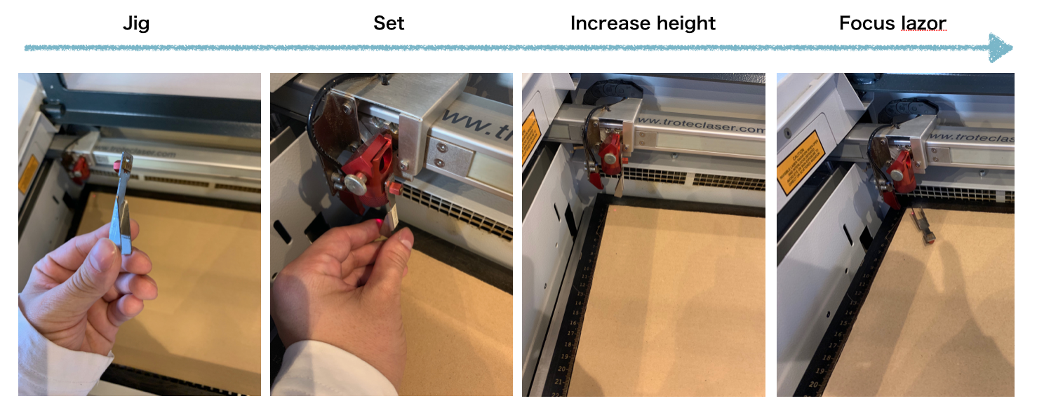
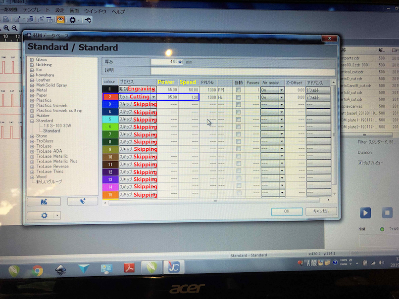
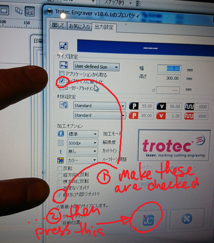
- Output setting of created data

–Note–
Work size (maximum data size):600✗300
- Emergency stop
- Stop mark: Until the stroke ends
- Square button and Open the lid: Forced stop on the spot
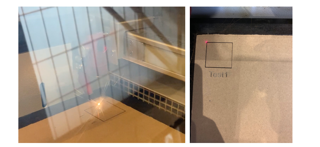
◯ Output result#
| Test1_Parameter | Power | Speed | Frequency |
|---|---|---|---|
| Cut | 95.00 | 1.20 | 1000Hz |
| Sculpture | 50.00 | 50.00 | 1000Hz |
◯ Just find a good point#
- Based on test 1, Illustrator creates data
- Load Trotec Speedy’s color palette
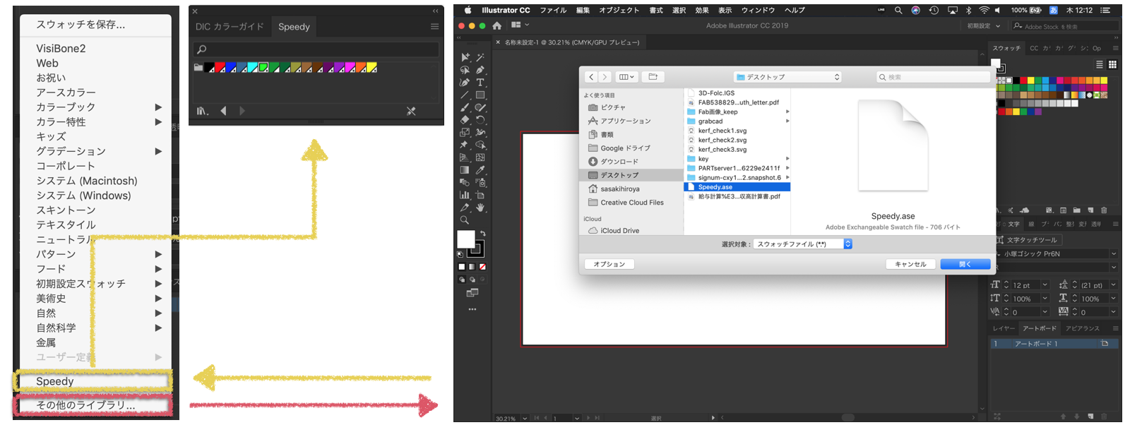
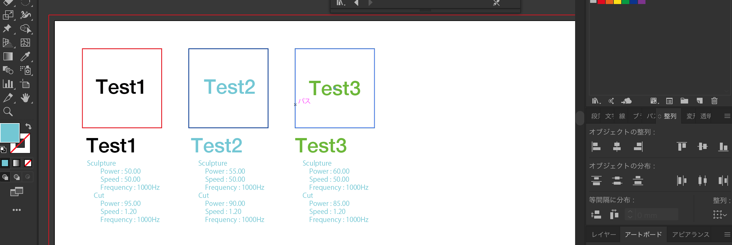
- Cut decreases by 5, Sculpture goes up by 5
| Power | Speed | Frequency | ||
|---|---|---|---|---|
| test1 | Cut | 95.00 | 1.20 | 1000Hz |
| Sculpture | 50.00 | 50.00 | 1000Hz | |
| test2 | Cut | 90.00 | 1.20 | 1000Hz |
| Sculpture | 55.00 | 50.00 | 1000Hz | |
| test3 | Cut | 85.00 | 1.20 | 1000Hz |
| Sculpture | 60.00 | 50.00 | 1000Hz |
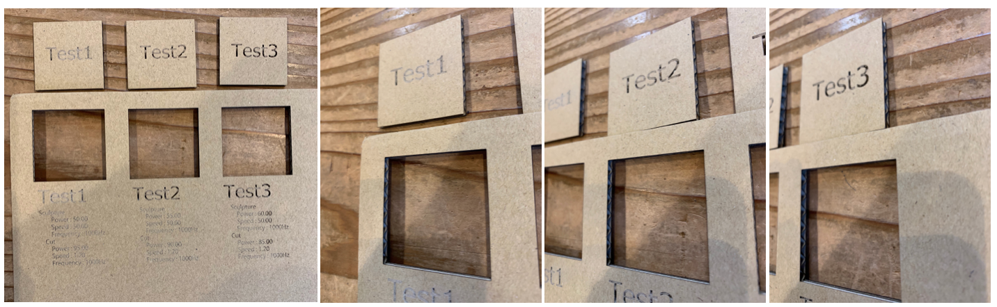
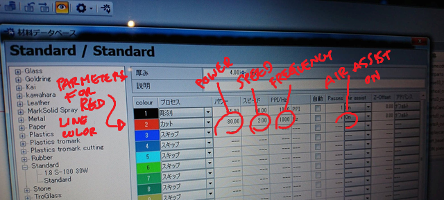
◯ The parameters to be tested are determined#
| Experiment parameter | Power | Speed | Frequency |
|---|---|---|---|
| Cut | 85.00 | 1.20 | 1000Hz |
| Sculpture | 55.00 | 50.00 | 1000Hz |
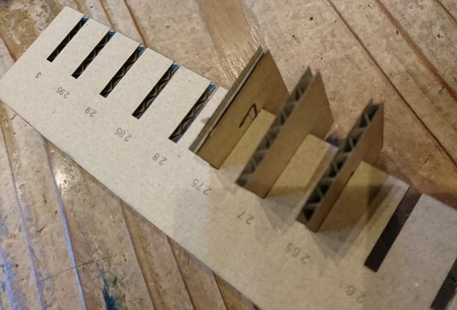
press-fit test (Yosuke)#
For our individual assignment of press-fit construciton kit, we tested optimal parameter of kerf.
First, we made the data for testing the optimal kerf parameters. I used a tool to generate kerf check parts (by Mr. Daisuke Doyo in Fab Academy 2018). I generated a kerf test parts to check from 3.0 mm to 2.41 mm in 0.01 mm intervals. The parts I made are here:


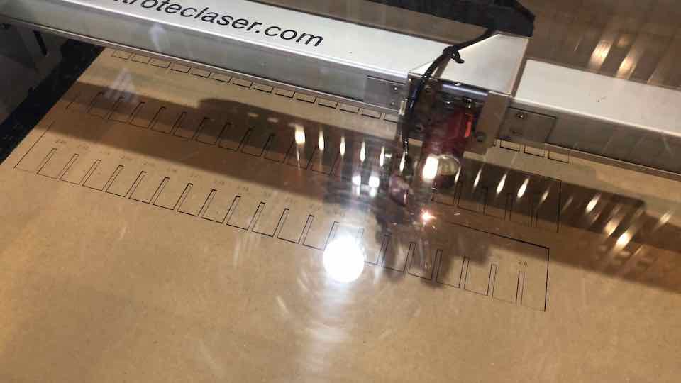
We imported those svg files into the PC that connected to the Trotec. Then, we set the parameter for cutting. Here, as we seeked above, we set the parameter: Power = 85 and Speed = 1.2.
Then, we started the cutting. The cutting process took about 4 minutes to finish.
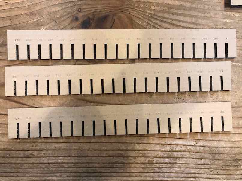
We made two set of the parts in order to assemble the same parameter of kerf.
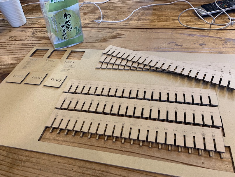
After cutting, we tested the kerf by assembling same pitch of kerfs.
Finally, we found out the optimal kerf would be 2.5mm.
TEST Files
- Kerf Test file between 3.0 mm ~ 2.81 mm [SVG]
- Kerf Test file between 2.8 mm ~ 2.61 mm [SVG]
- Kerf Test file between 2.6 mm ~ 2.41 mm [SVG]
Team B: Laser Cutter settings and Press-fit Tests#
Laser Cutter Settings Test#
Notes:
- Cut a square out of cardboard to check machine kerf…
- Draw square on correl…30mm x 30mm…line thickness 0.001mm
- Use RED as line color (will be used by Job Control to identify parameters)
-
Select “Print” to send instructions to Print Control software for the laser Cutter
-
Select file from print control…preview to make sure all is ok
-
Red color associated with specific laser power and speed settings…
-
Turn on laser printer…make sure top is closed while machine goes thru its calibration step
- Use sleep switch to turn off fan until ready to cut (it’s noisy!)
- Set material (cardboard) on stage (the black metal bottom that moves up and down)…we taped the cardboard down because it was a bit warped
- Focus laser using a little tool that attaches to the side of the laser head (magnetically) and falls off when it touches the cardboard surface…we were told to make sure to focus the laser at the desired origin point of the cut
- Link job control software to machine (with the button the looks like a USB cord)
-
Align cut shape with location of Laser on the Job Control screen…click and drag it into position
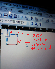
-
Close lid to print/cut
- Laser cutter power range: 0-100…95 the practical max
- Laser Cutter speed range: 0-100
- …if you want to stop job…open lid or press pause
- …must observe the print job, don’t leave the machine…prepare fire extinguishing equipment (wet towel as primary, other as secondary)
Test Cutting
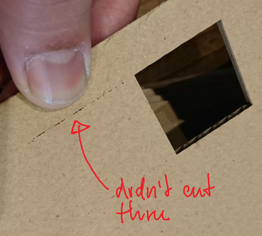
Test 1: P = 50, S = 10…outcome: VERY fast, doesn’t cut thru, no burn
Test 2: p = 60, S = 5…outcome: doesn’t cut thru, no burn
Test 3: P = 70, S = 2.5…outcome: almost cut thru, no burn
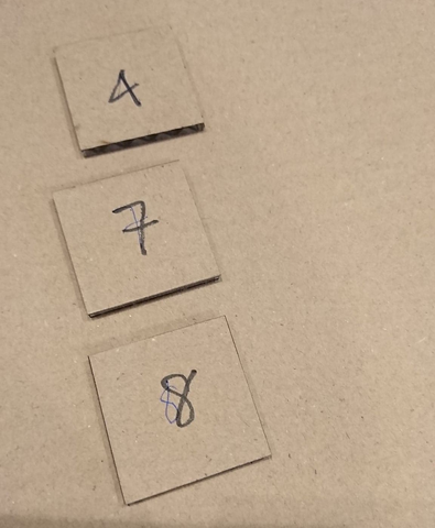
Test 4: P = 80, S = 1.25…outcome: 100% cut thru, no burn…hole distance, 30t.4mm/square width, 29.65mm…kerf = 0.75mm/2 = 0.375mm#

Test 5: P = 90, S = 5…outcome: no cut thru, no burn
Test 6: P = 90, S = 10…outcome: no cut thru, no burn
Test 7: P = 90, S = 2.5…outcome: 95% cut thru, some burning…hole distance, 30.2mm/square width, 29.8mm…kerf = 0.4mm/2 = 0.2mm#
and the winner…
Test 8: P = 80, S = 2.0…outcome: 100% cut thru, some burning…hole distance, 30.3mm/square width, 29.75mm…kerf = 0.55mm/2 = 0.275mm#
Press-Fit Test#
-
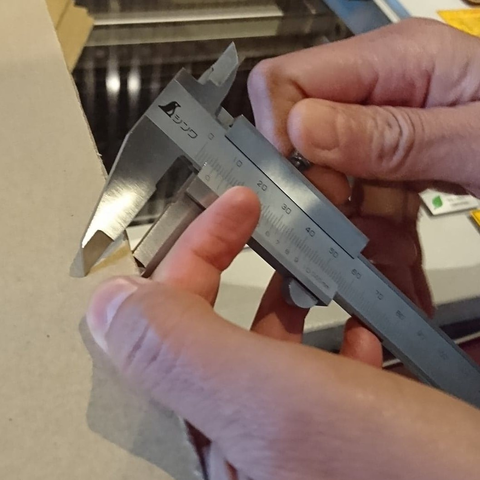
Measure cardboard thickness with calipers…3.0mm confirmed
-
Used SVG script (by Mr. Daisuke Doyo in Fab Academy 2018) to make “Test Comb”
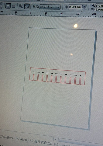
- Export SVG ‘Test Comb’ image to Corel Draw
- Cut on Laser Cutter using Test 8 parameters
- engraved text onto ‘Test Comb’…engraving parameters: P = 75, S = 50…clear text engraved

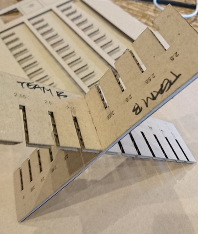
Test Comb Observed Results:
- 2.5mm…very tight
- 2.65mm…firm fit, a bit of force to remove once seated
- 2.70mm…best fit, easy in and out
- …other slot width too tight or too loose