Week 8: Computer-Controlled Machining
This week's tasks:
- Group assignment:
- Testing runout, alignment, speeds, feeds, and toolpaths for the CNC machine in Fab Lab Oulu
- Link to the Group Assignment Page
- Individual assignment:
-
Making something big
- 3D esigning something big
- Prepairing the 3D design for cutting with CNC router
- Cutting it
Challenges:
- I faced lots of challenges while I was doing the 3D design becuase I did 4 times from scratch the design and eventually it worked. Each time, I could not identify what the problem was becuase I was following the tutorial and the features was kinda advanced. Of course I learned lots of new functionalities of Fusion 360 through this design process but as I said it was hard to figure out where the problem was. So special thanks to Jari (fab lab oulu's instructor) that observed my design process while I was doing that and it was a considerable assistance to keep in the right path.
- After cutting with CNC machine, it was a very tedious task to manually separate the pieces and to polish them. Some are not familiar with different machines that could make their life easier (as I also did not). So instead of using a cutter to bring out the pieces that are not cut completely through, one could use for example electronic saw.
Considerations:
- Although it is challenging specially for a beginner in 3D design, I highly suggest parametric design. Since you would be able to change the size easily. I even changed the size in a way that I could manage to have a round table instead of a chair!
- In order to avoid manually cutting the material, which gave me really hard time I could take 2 actions:
- I could have made an other milling file from the same model, that has only one milling track deeper than on the first one (to cut 12 mm deep instead of 11 mm deep).
- Or I could re-set the z-axis and run the milling again, hoping it would go through this time.
- So because I did not do so, I had to use:
- Firstly, table saw to cut the material to as smaller pieces as possible in order to be able to fit them on tablesaw.
- Then I used tablesaw for cutting more precisely and separating different objects from the material.
- Then I had to use sanding machine to remove the excesses of the material.
Technology used:
- Fusion 360
- Laser Cutting Machine
- CNC Machine
- Electronic Saw
- Polishing Machine
Designing Something Big
My final project do not have a big piece. Therefore, I decided to make a chair for myself. So I browsed through the web to get some ideas for chair designing. I very much liked this one. So I followed the tutorial for designing this chair.

- Creating new component named seat. Activating seat component by clicking on it.
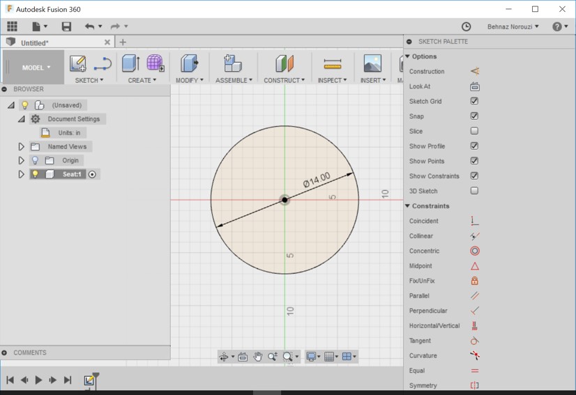
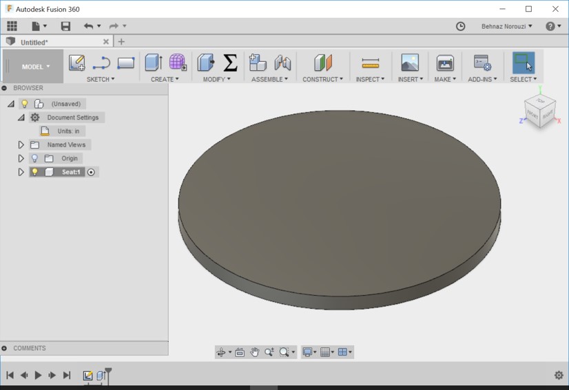
- Creating new sketch for seat component. And drawing a 14 inch diameter circle Then stopping sketch and extruding it to the desired thickness. I used 0.72.
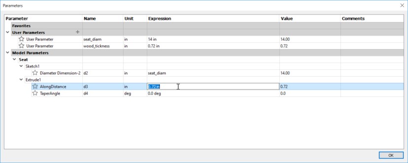
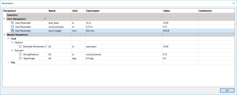
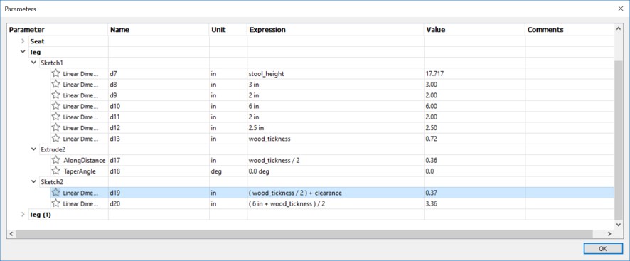
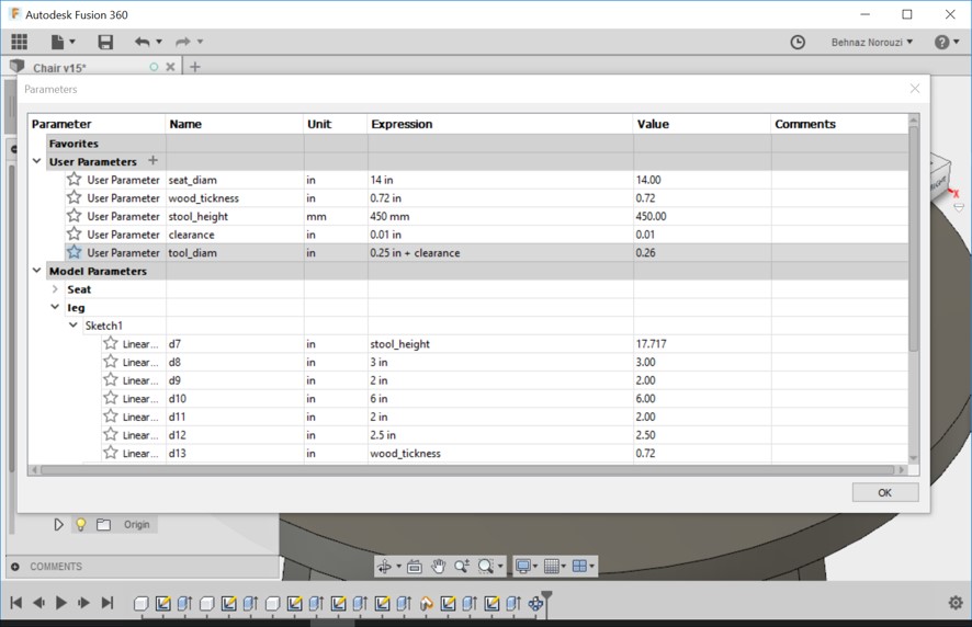
- Defining user parameters. seat_diam:14, wood_tickness:0.72. I also replaced sketch diameters that was shown by default with number, with new diameters that I had defined.
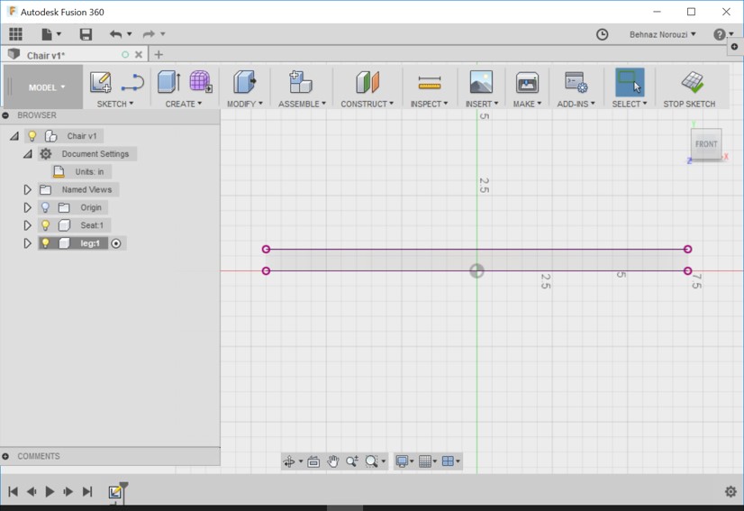
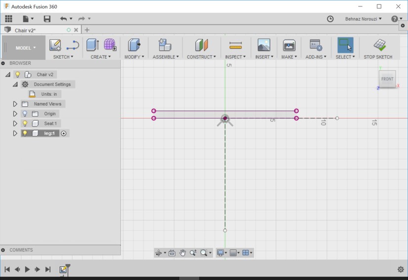
- Creating leg component. Right clicking on it and activating it. And create a sketch. Using project to project some existing geometry.
- Drawing a line from origin to the straight down. And drawing another line from origin straight out. Now turning the lines into construction lines by: Selecting both lines > right clicking > Normal/construction.
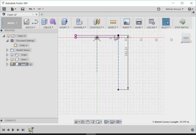
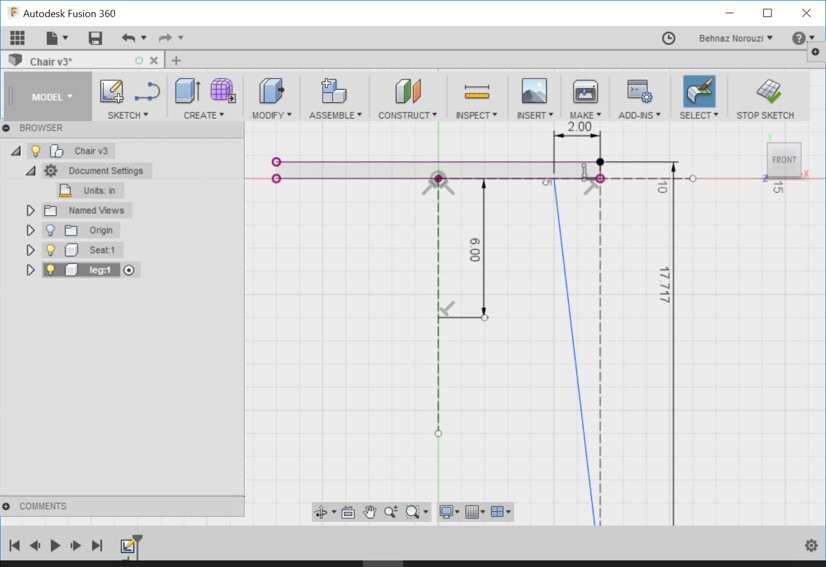
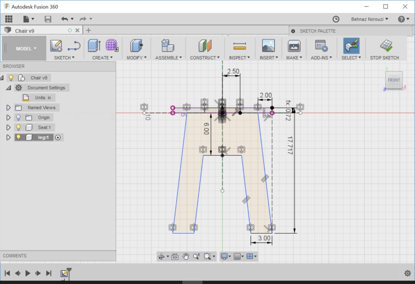
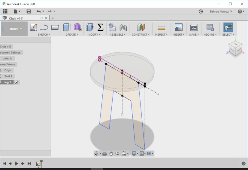
- Drawing a line from the top right edge to straight down and setting its diameter to the height of the stool that I want, which is 450 mm 817.717 inch). Then turning the line into a construction line.
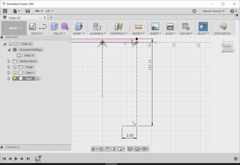
- Drawing legs. To be 3 inches across.
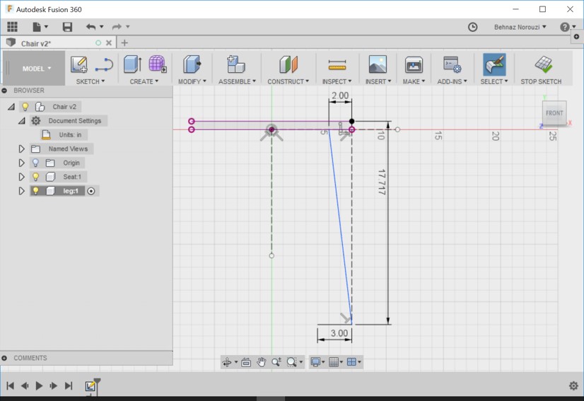
- Drawing a line that extends up to the base of the seat and 2 inches from the outside of the seat.
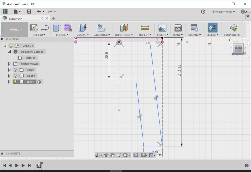
- Drawing a line straight across. The middle portion of the leg to be 6 inches below the base of the seat.
- Then connecting the end of this line to the end of the 3 inches lien (leg line). And make it parallel to the line in front of it (using parallel constraint).
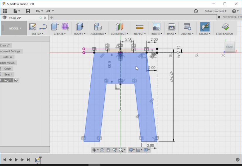
- Now extending up the middle part of the leg ( the purpose is to design in a way that it is possible to put it all together without any fasteners.
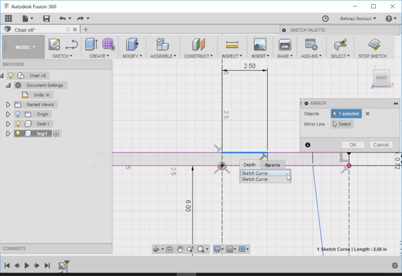
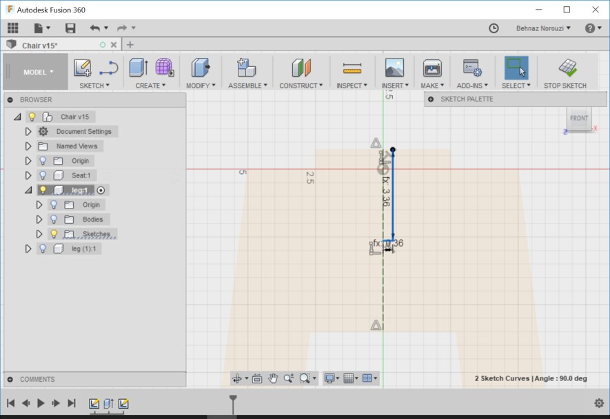
- Drawing these 3 lines that are selected in the picture below.
- Defining values for lines.
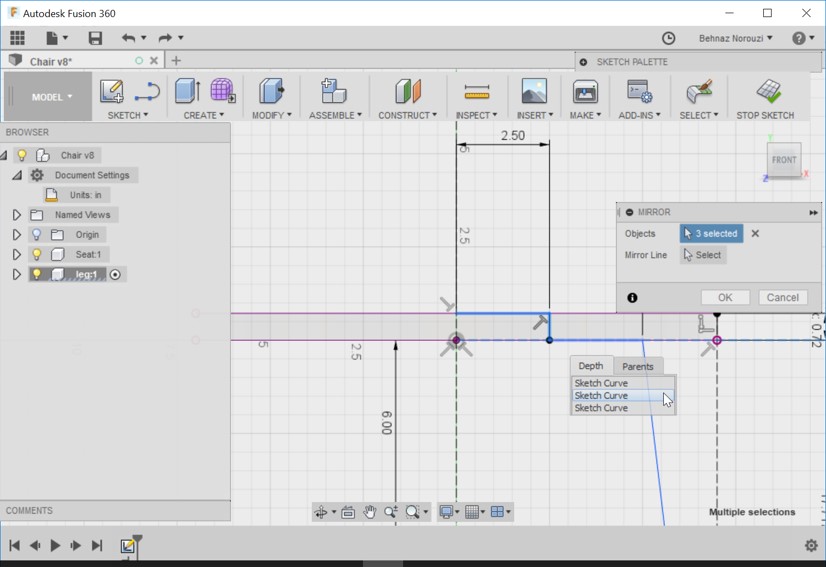
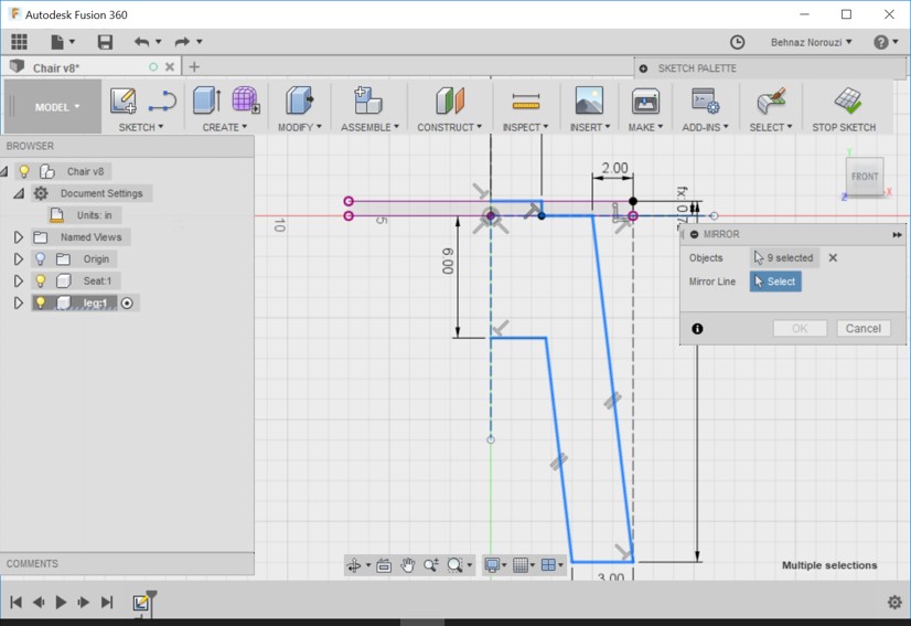
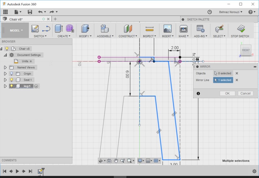
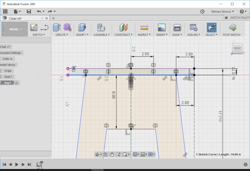
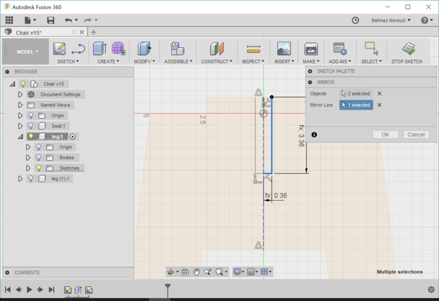
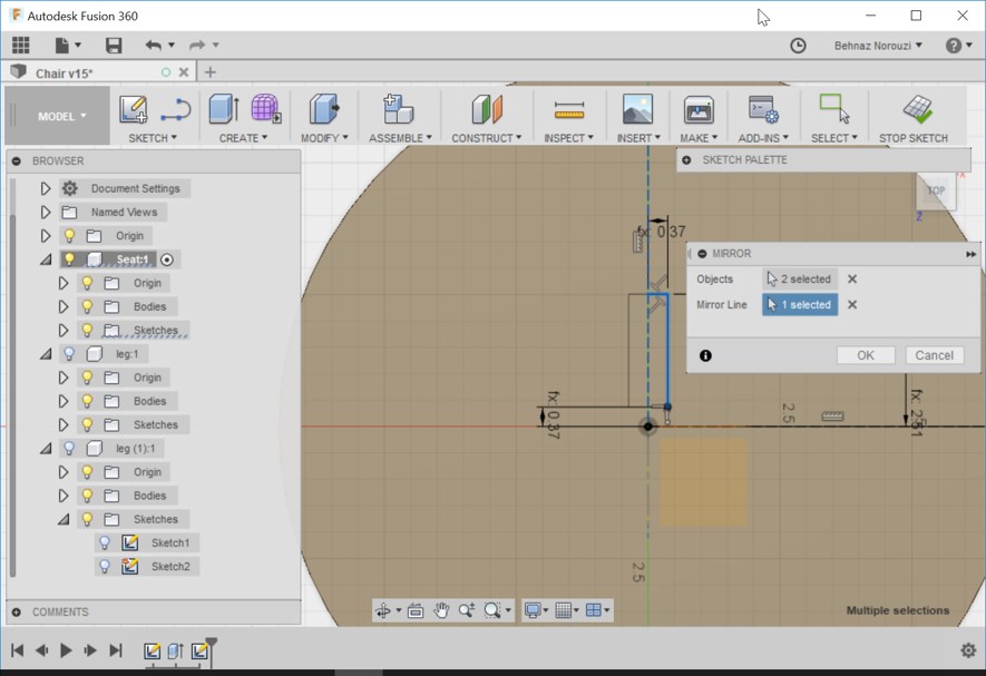
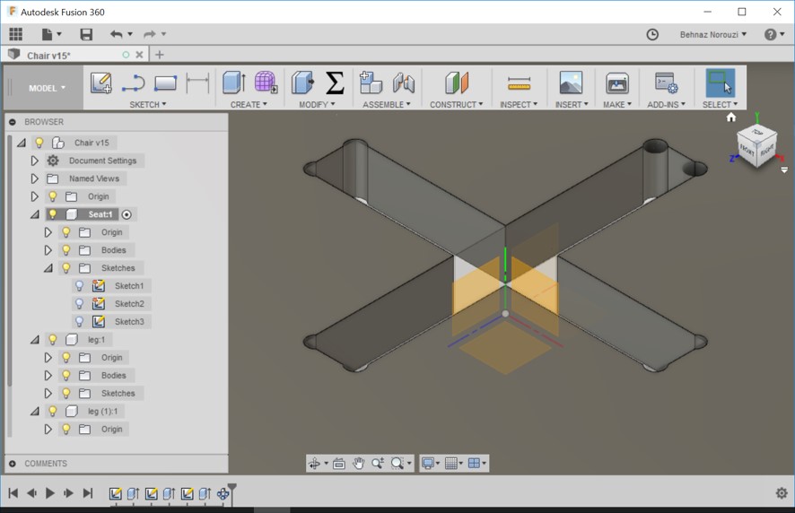
- Mirroring everything about this construction geometry. Choosing mirror and picking the lines (those 3 that are selected in the picture). Left click and hold and sketch curve. And also selecting the mirroring line.
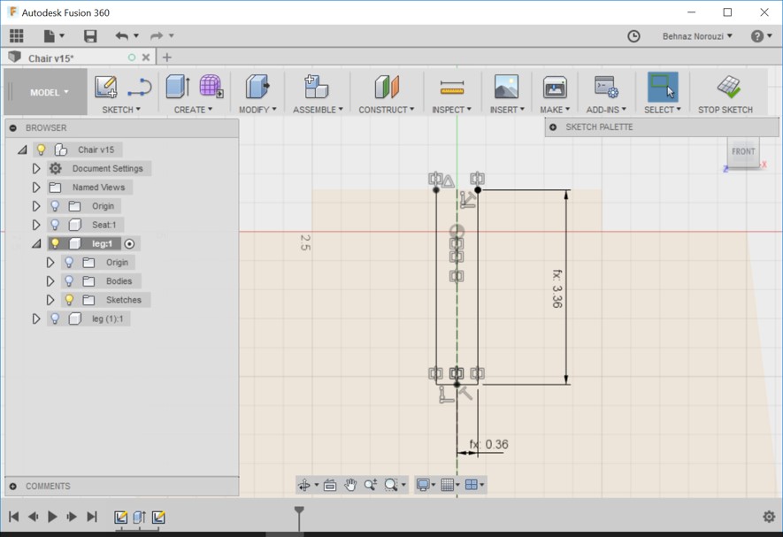
- As you see in the picture, now when I hover on it, I do not see the whole parts selected as 1 object.
- Selecting the line (showed in the picture) > right click > Normal/Construction.
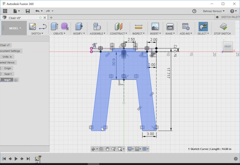
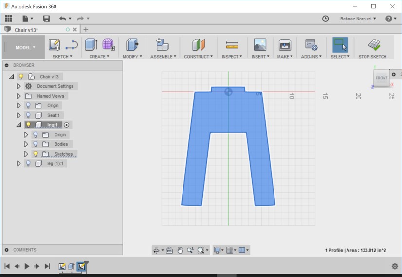
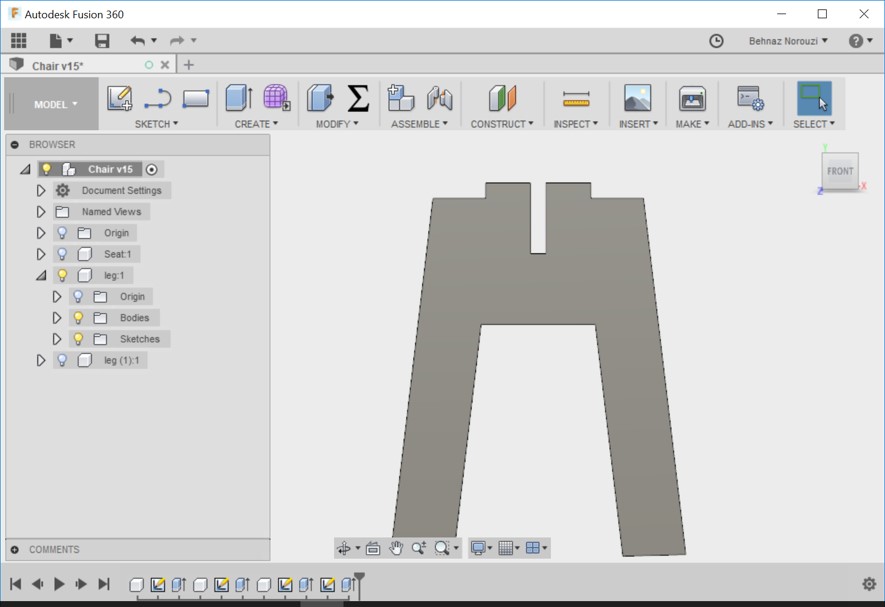
- Now we have 1 clean profile.
- I stopped sketch to see this view:
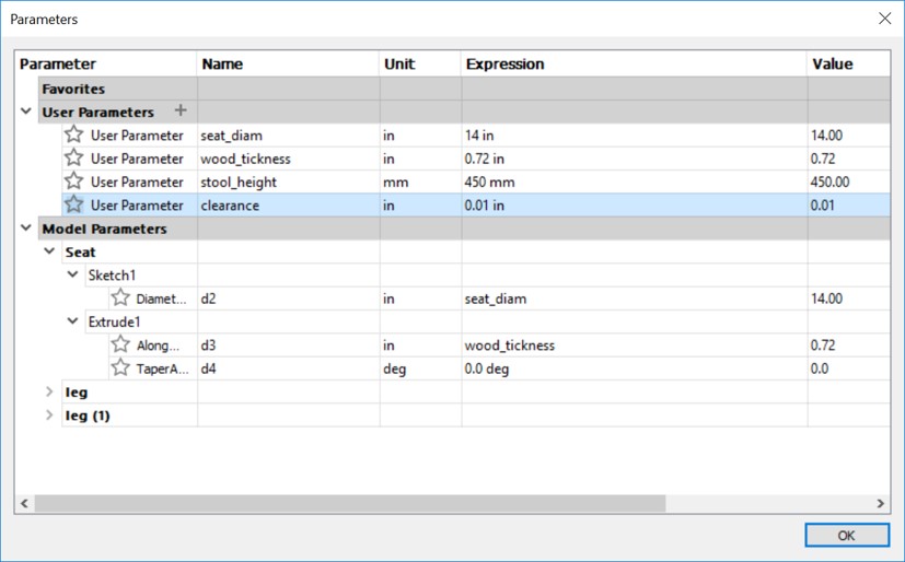
- Adding another parameter: stool_height, 450 mm.
- Extruding this profile out to the wood_tickness. Changing direction from 'one sided' to the 'symmetric'. Changing the distance to wood_tickness/2.
- Selecting Chair Component.
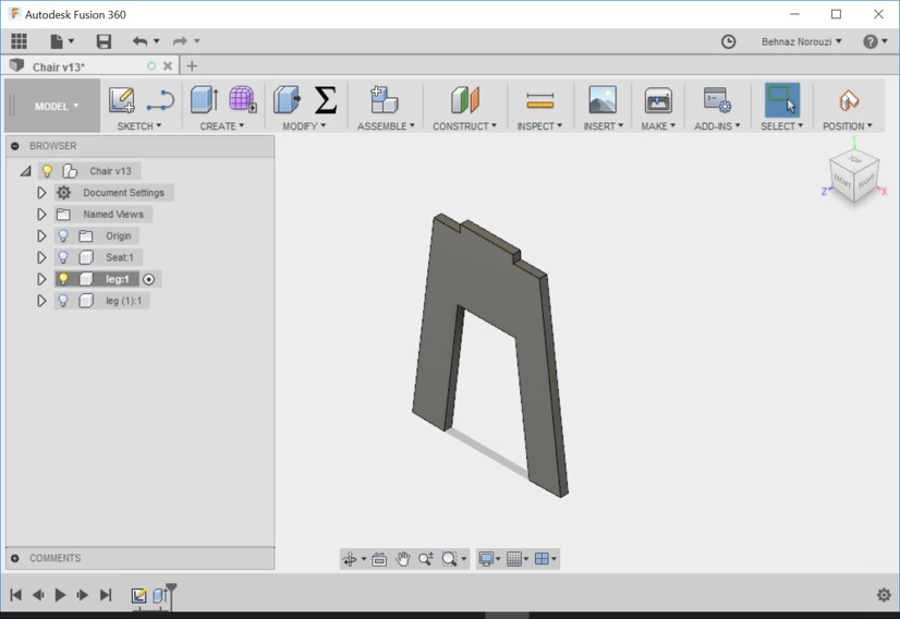
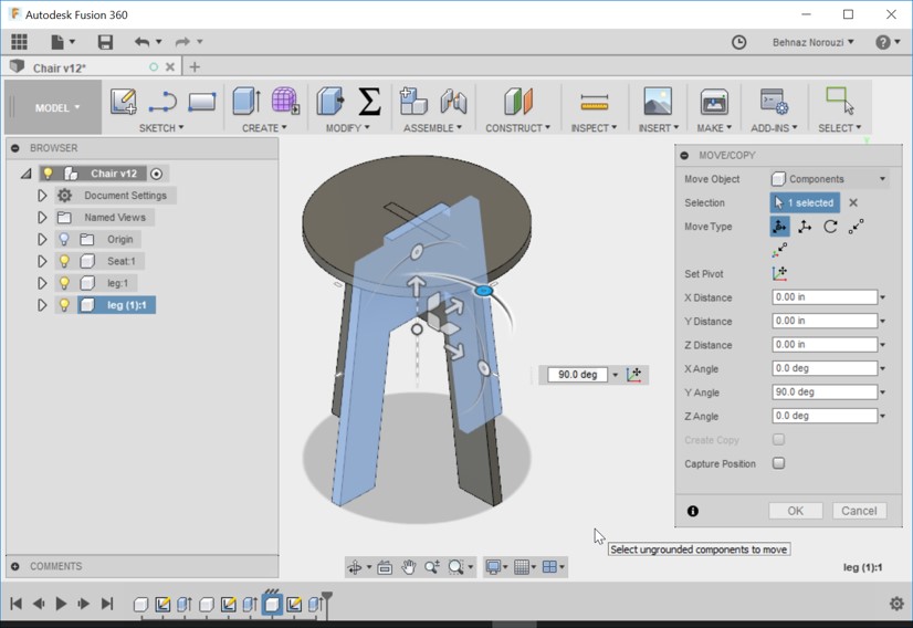
- Going on the leg component > right click > copy And then selecting chair component > right click > paste new. (paste new becuase we don't want the changes to one of them affect the other one so instead of paste, we use paste new) and rotate it 90 degrees.
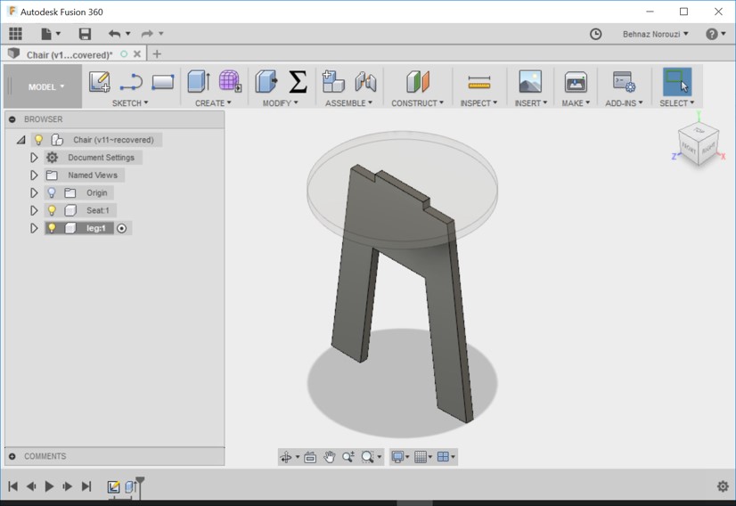
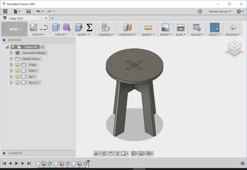
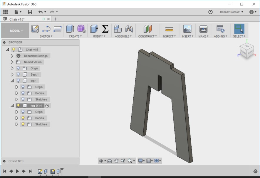
- Now we have the basis for the stool.
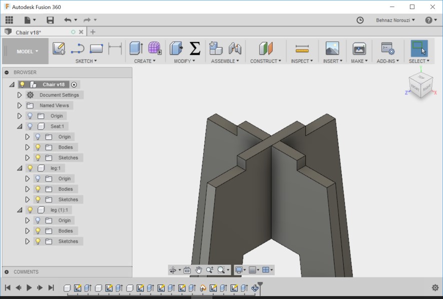
- Creating some slots in both of these legs. One at the top and one at the bottom so that all fit together. Right click on leg1 and activate it and hide the other components so that they are not in the way.
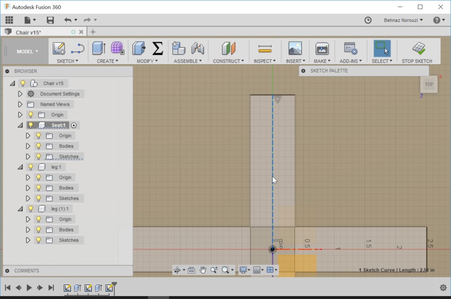
- Creating a sketch on this face. And hide the body. (just to have a clean sketch profile)
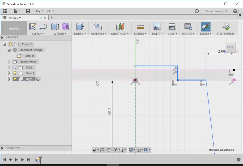
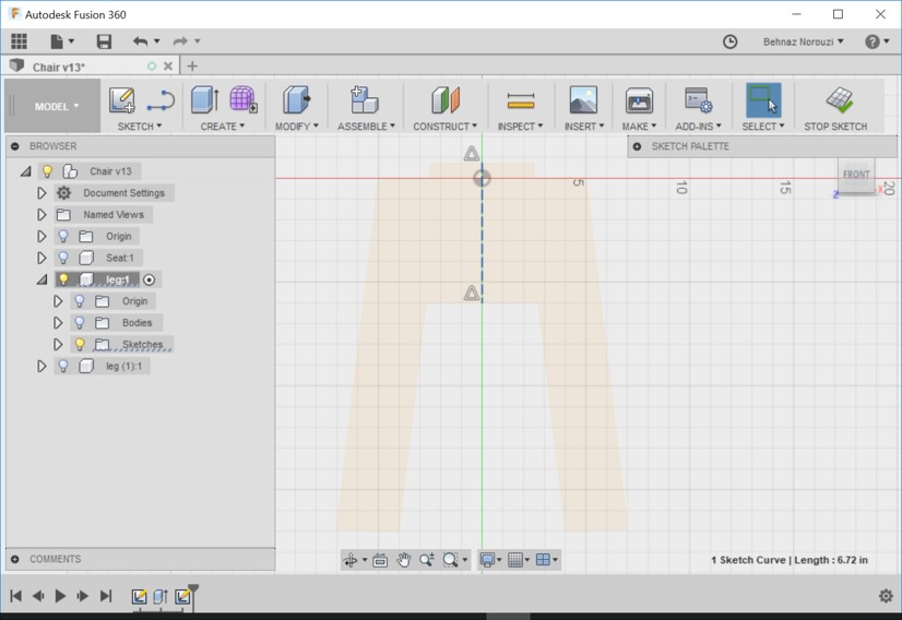
- Drawing a construction line from midpoint to midpoint.
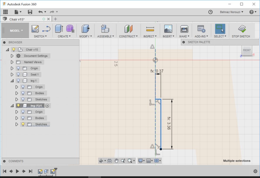
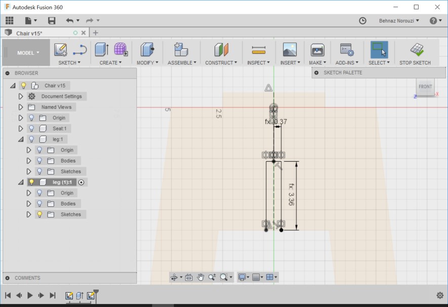
- Drawing the slots that we want. Drawing 2 lines. Setting the horizontal one to half of the wood tickness. And set the parameter for the vertical one to (6+wood_tickness)/2.
- Now mirroring the 2 curves about the central line.
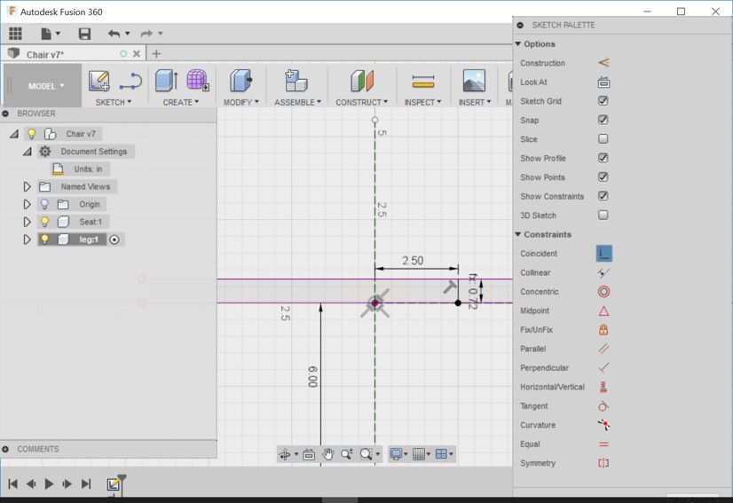
- Setting new parameter named clearance with the value of 0.01 inch. Change parameter(shown in the pic) with the value of wood_tickness / 2 to (wood_tickness / 2) + clearance.
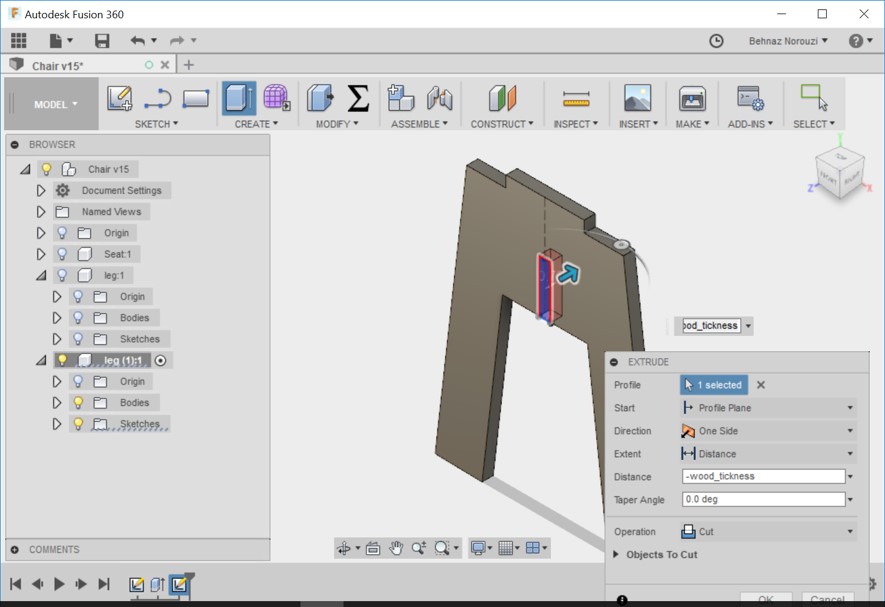
- Stopping sketch, turn the bodies back on and extrude it with the value of -wood_tickness.
- Showing and activating the second leg and creating the exact same thing on the bottom instead of the top. Hiding bodies folder. Drawing the construction line. Drawing the horizontal line with the value of (wood_tickness/2)+clearance. Drawing the vertical line with the value of (6+wood_tickness)/2.
- Mirroring the lines.
- Stopping sketch. Extruding it with the value of -wood_tickness.
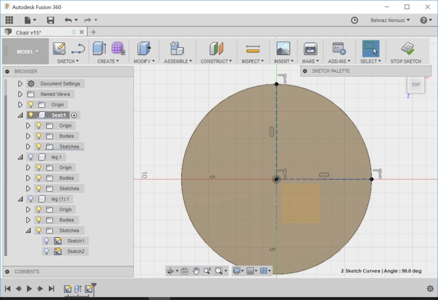
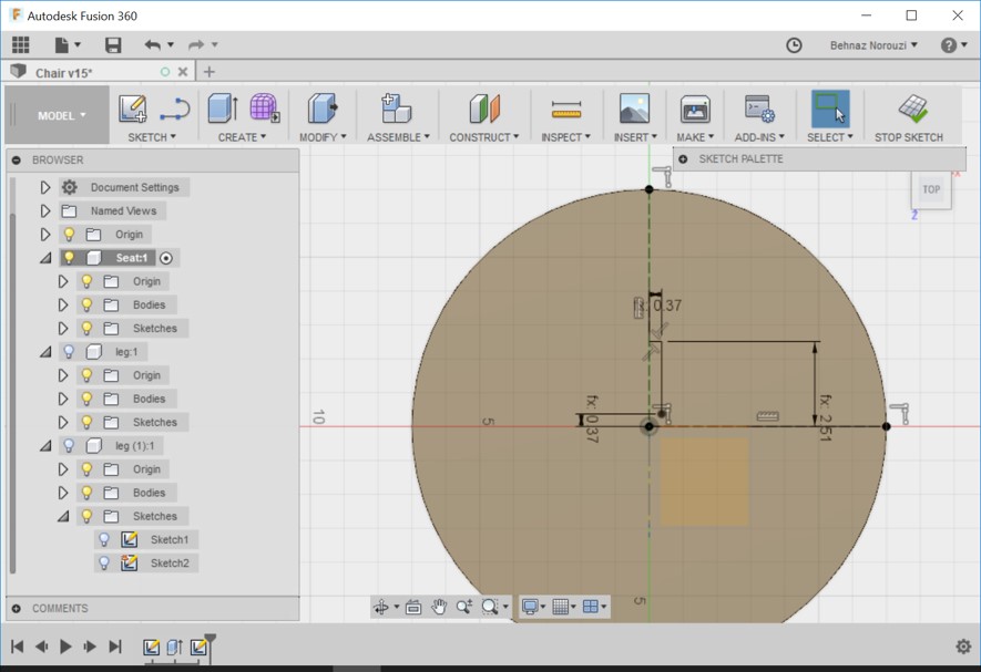
- Hiding legs and creating a new sketch on the top surface of the seat component. Drawing 2 construction lines.
- Drawing 2 lines (as you see in the picture). Horizontal line is (wood_tickness/2)+clearance inch. And defining 2 other distances as you see in the picture.
- Mirroring the lines.
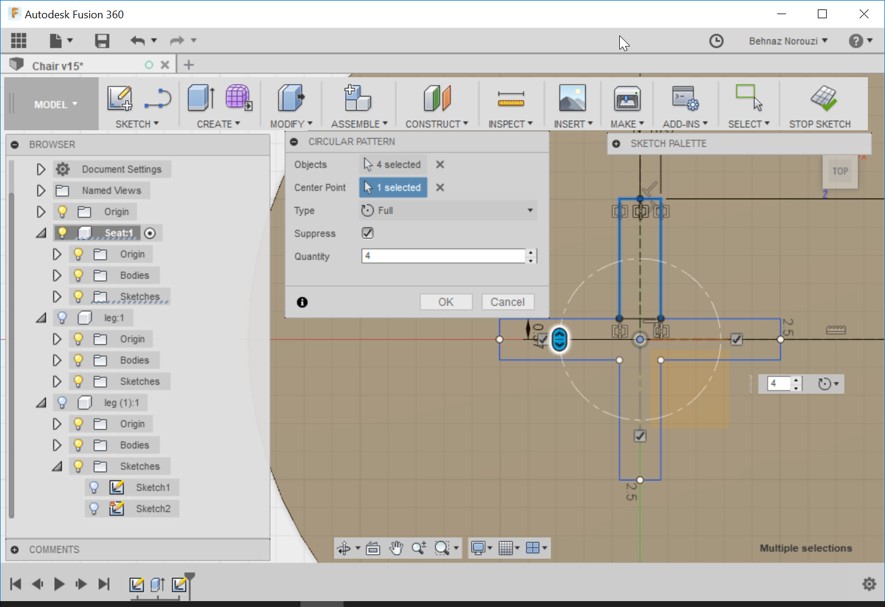
- Circular pattern: to pattern all 4 lines about the center. Chaning the quantity to 4.
- Stopping sketch. And extruding it down to -wood_tickness.
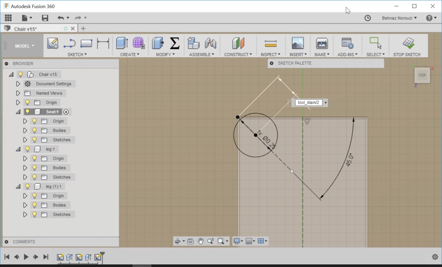
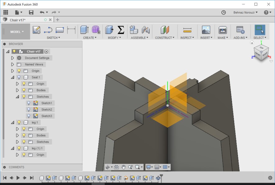
- Making 90 gedree angle in the corners for CNC round tool. Activating the seat. Creating the sketch. Creating a user parameter called tool_diam and setting it to 0.25 inch. Drawing a construction line to the center. Drawing another one with 45 degree angle. Drawing a circle with tool_diam size.
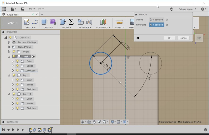
- Mirrorng the circle.
- Stopping Sketch. And Extrude the 6 profiles (showed in the pic) by the value of -wood_tickness. Changing the operation to 'cut'.
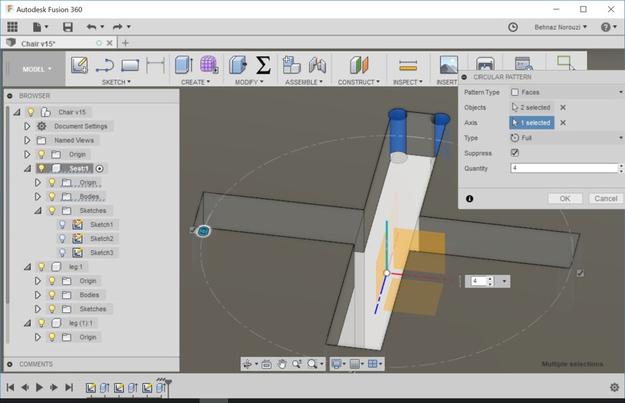
- Creating a pattern for all the corners. Create > pattern > circular pattern.
- Adding clearance variable to the tool diameter.
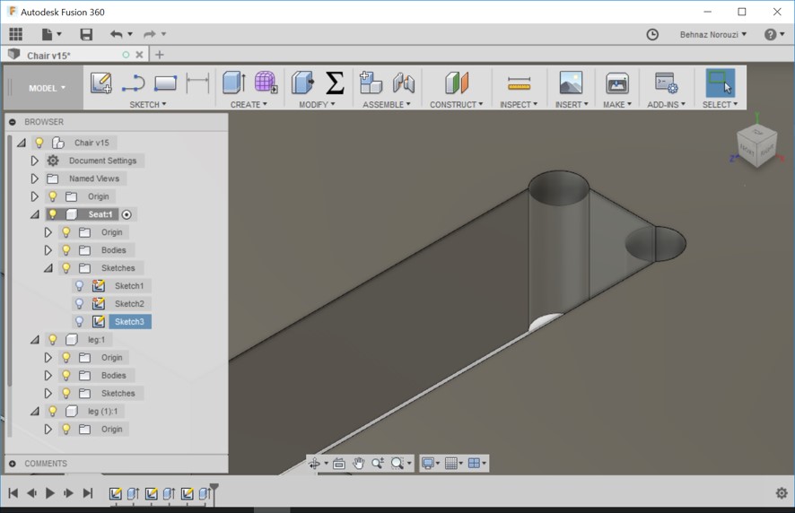
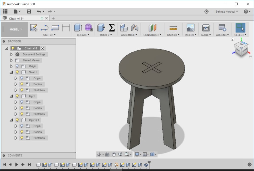
- Here is the result.
- I hided the seat component to ckeck the legs. And I noticed something is wrong as you see in the picture, the up right corner has a different shape compared to others. It happened probable while trying to corner the edges for the tool diameter!
- With the help of one of Fab Lab mentors, John, I figured out the problem. The problem was that I had forgotten to hide the visibility of the leg components. So I turned their lamp off and did the circles for tool diameter and the following steps again.
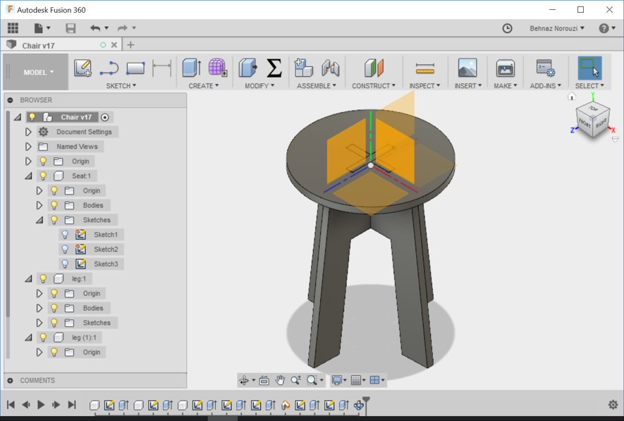
- And here is the result :-)
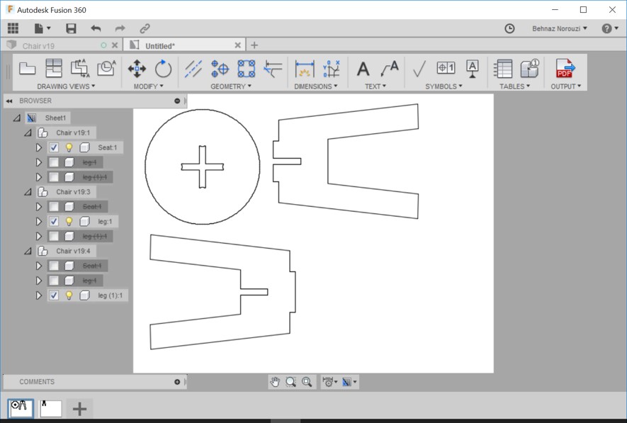
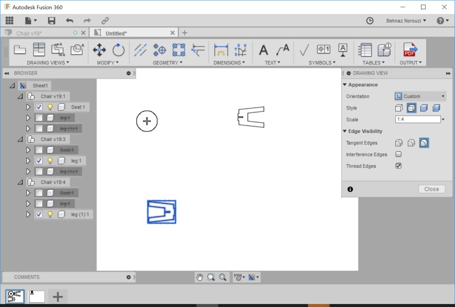
- Now as Neil suggested, I decided to make a smile prototype with laser cutting machine to check how it looks like. So I prepared the files and exported as pdf. I made 3 new drawing for seat,leg1 and leg2 from the design in a same sheet. And I set the scale to 1:4 becuase I wanted a small prototype.
- And then I opened the pdf in Inkscape and made the file ready for laser cutting. And here is the result:
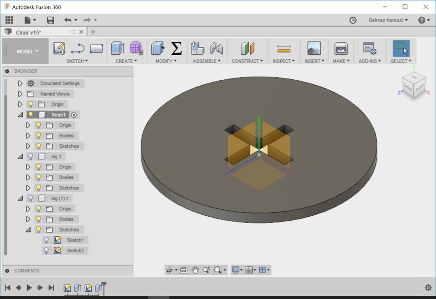
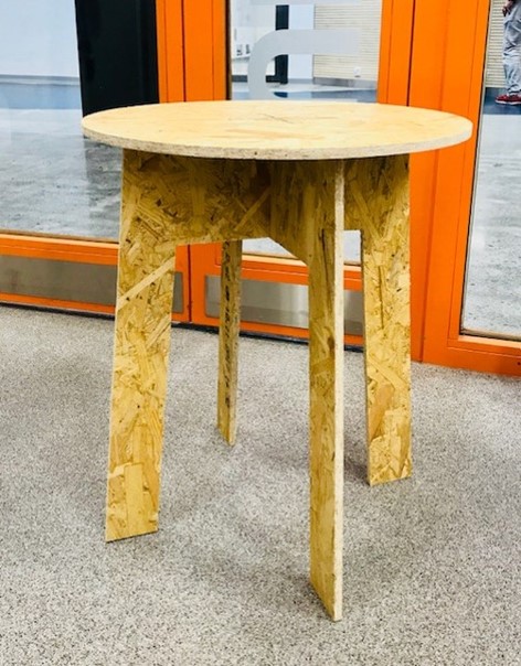
- I changed the diameters so that I could have a table instead of a chair. And it was a very easy task since the design was parametric.
Creating the Toolpath
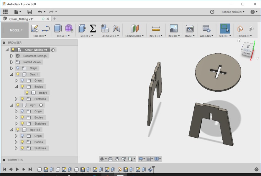
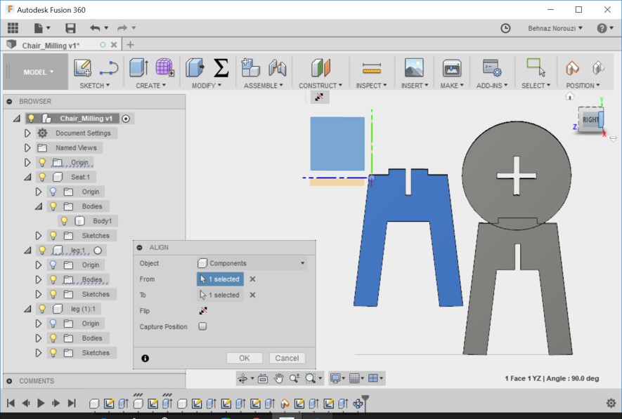
- I copied my design file for preparing it for milling in a separate file. I named it stool_milling. And I moved seat and leg components to take them apart. I aligned all the components to a same plane.
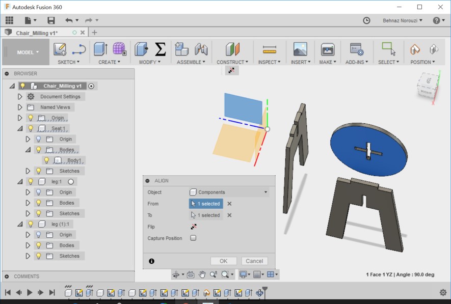
- I aligned the seat component: Modify > Align
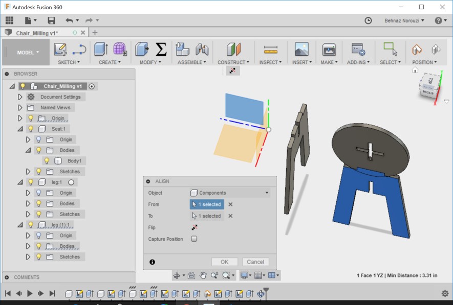
- I aligned leg1 component.
- I aligned leg2 component.
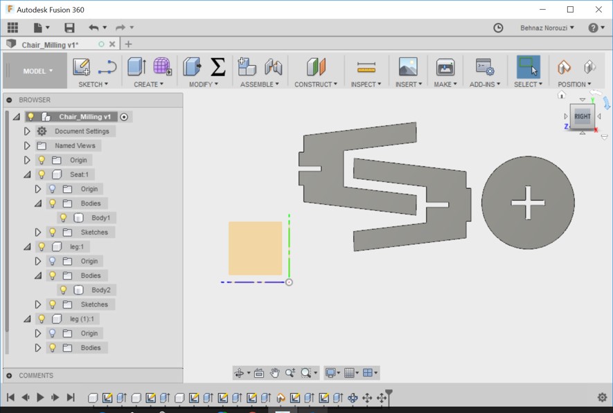
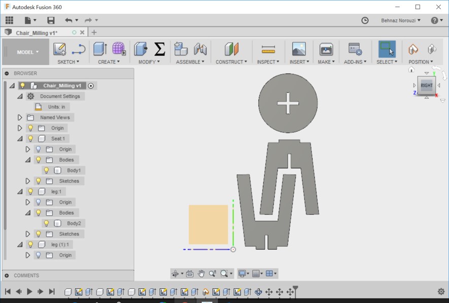
- As you see all the components are aligned on a same direction.
- I oriented items in a way that we have the less waste of the material.
- CAM functionality is intergrated in Fusion 360 and could be updated easily.
CAM feature is the use of software to control machine tools.
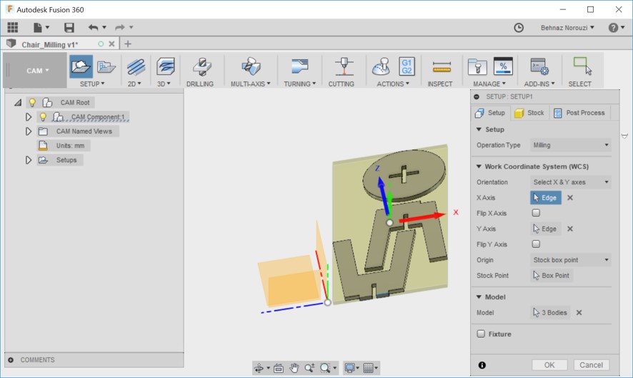
I switched to the CAM workspace (Model > CAM) for creating a version for CNC machine.
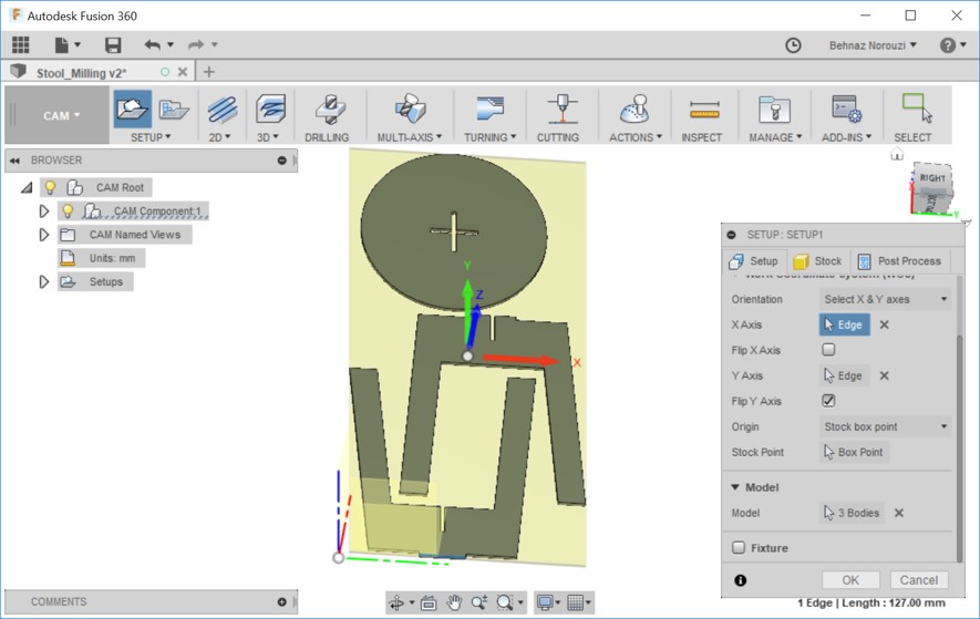
Through JOB SETUP, I defined my stock for simulation. From setup > new setup > setup tab, I chose 'Milling' for the Operation Type and I chose 'select x&y axes' for orientation.
And I chose the origin for X axis and Y axis. - I chose 'stock box point' for Origin.
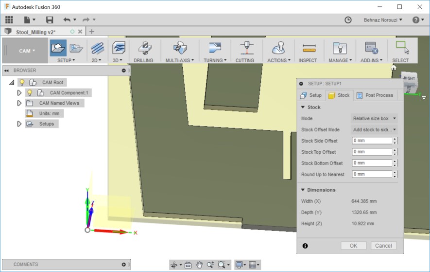
- On the Stock tab, I changed the stock sizes that were automatically calculated by fusion 360 based on my model and I set stock values to 0 mm.
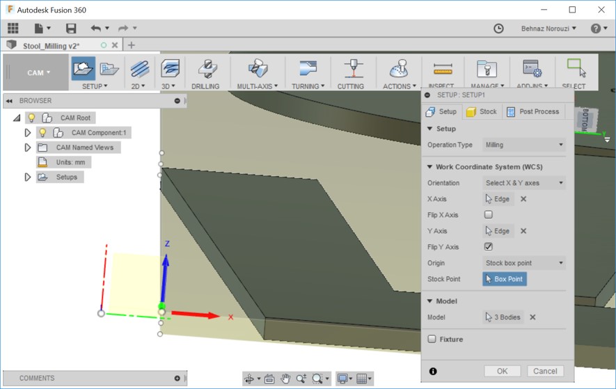
- Now under the setup tab, I selected the box point for the stock point. As you see in the following pictures, I selected a point on the stock bounding box for the WCS origin.
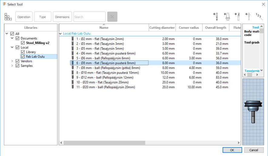
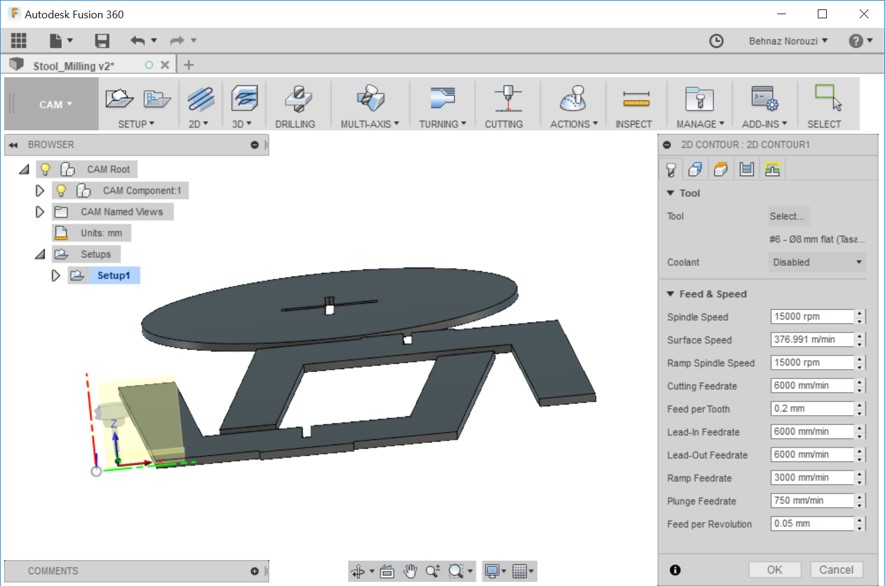
- From 2D > 2D Pocket > setup > select tool, I imported FABLAB ROUTERI TOOLS 2018-2.hsmlib library to the local in a way that I mention in the following:
(Manage > Tool Library > Local > Right Click > Import Tool Library > selecting the FABLAB ROUTERI TOOLS 2018-2.hsmlib that I had already downloaded to my my computer)
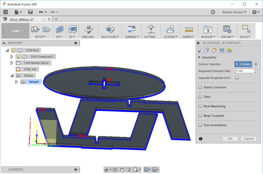
And then from the imported library, I chose 8 mm-flat. Because the diameter of the tool that I am going to use is 8 mm. - Geometry is a feature that allows us to pick the locations to be drilled. From 2D Contour > Geometry, I selected the bottom of the lines of 4 chains as you see in the picture.
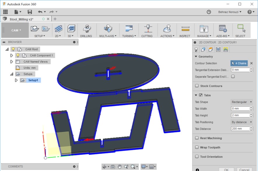
- In Geometry tab I checked 'Tabs' and those small pieces appeared around the components. Tab functionality is to keep the pieces still so that they do not move while milling. I changed tab distance to 200 mm.
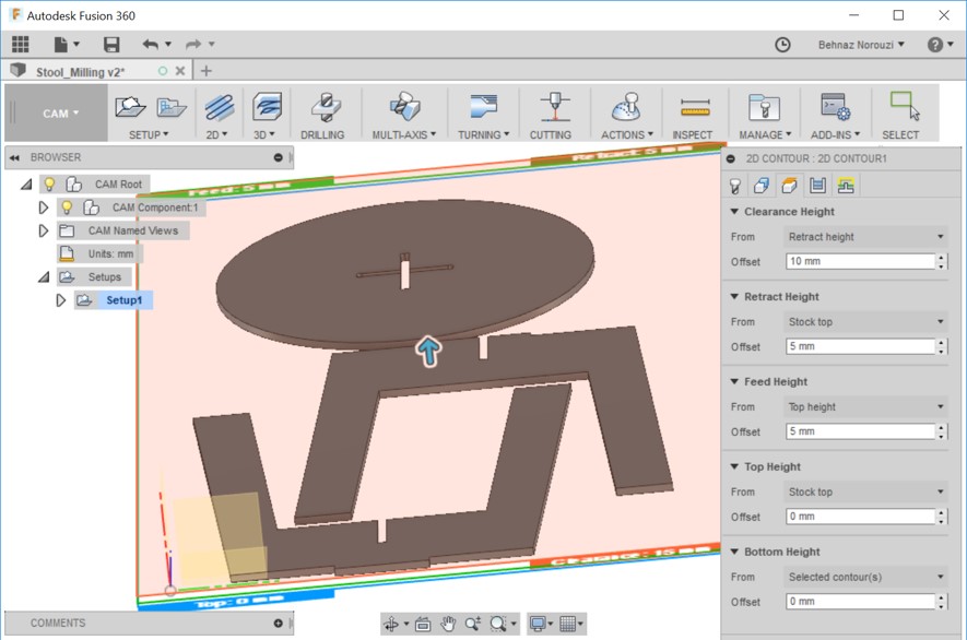
- Through the Heights tab, we could "Control the machining area by depth for most machining strategies". (Reference).
Clearance Height: From Retract height: offset 10 mm
Retract height: From stock to: offset 5 mm
Feed height: From top height: offset 5mm
Top height: From stock top: offset 0mm
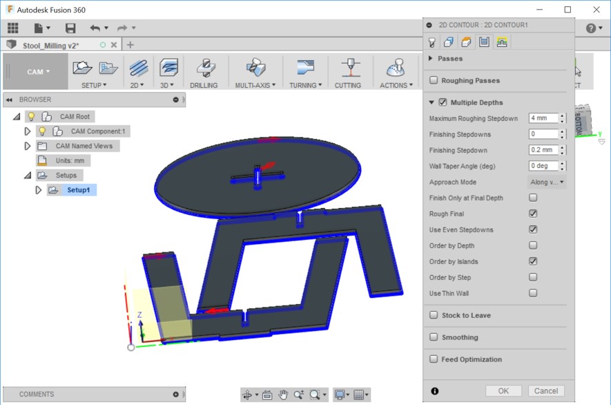
Bottom height: from selected counters: offset 0mm - On the Passes tab, I checked 'Multiple Depths', 'Rough Final', 'Use Even Stepdowns' and I unchecked 'Stock to Leave' option.
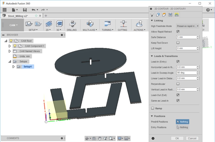
Maximum raughing stepdown: 4mm - I did not change the default settings on the Linking tab, which is as following:
Safe distance: 5 mm
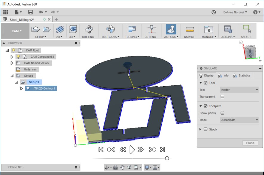
lift height: 0 mm - Then from Action > Simulate, I watched the simulation of the functionality.
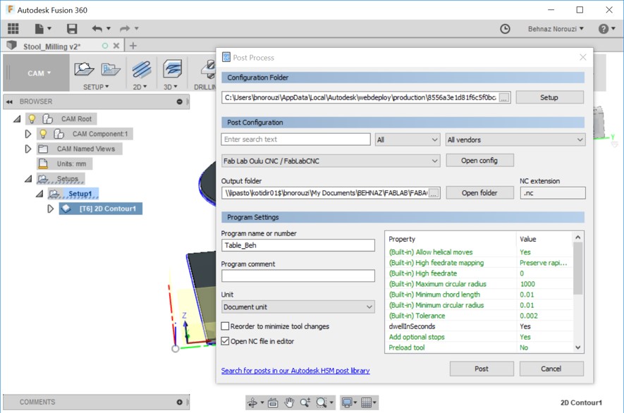
- I saved FabLabCNC.cps file on my computer and I placed the file into the configuration folder (You see in the picture). And I also specified the output folder for .nc file.
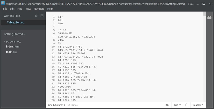
- And here is the G-code (.nc file). G-code is "used mainly in computer-aided manufacturing to control automated machine tools" (reference).
- I did a small modification and generated another .nc file afterwards.
2D Contour > Linking tab > Leads and Transitions: I unchecked lead-in and lead-out.
Cutting
- Checking the size of the file for choosing a proper piece of material that fits:
From CAM file: Setup > Stock > Dimensions
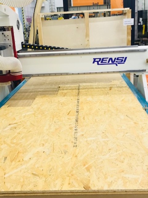
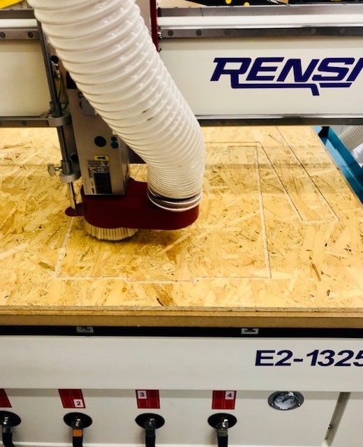
After figuring out the dimensions with help of Eino, I chose a piece of material (OSB board 12 mm) and placed it on the machine. - Then I turned the machine on.
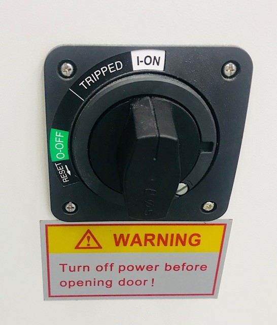
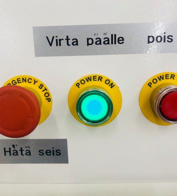
- Then turning the power on.
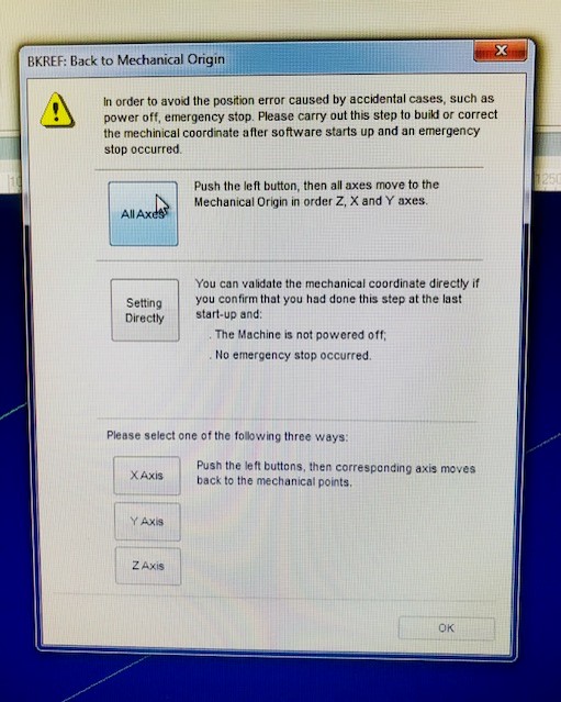
- Then I opened the NCstudio software on the computer and a notification popped up about Mechanical Origin. I chose "All Axes" option, which cause all axes move to the Mechanical Origin in order Z,X and Y axes.
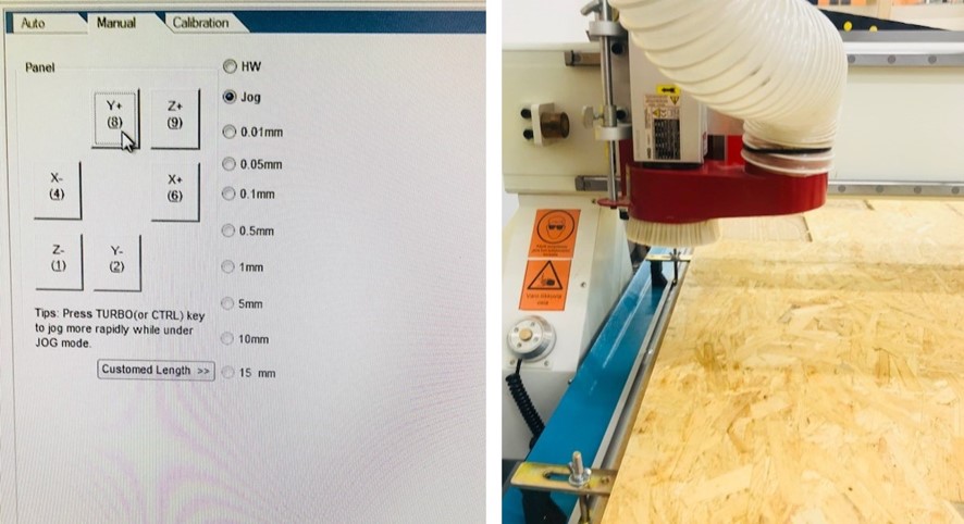
- On the right side of the screen there is a section with 3 options of Auto, Manual and Calibration. From Manual tab I chose Jog and I used the axis panel with Y+, Y-, X+, X-, Z+ and Z- to move the head.
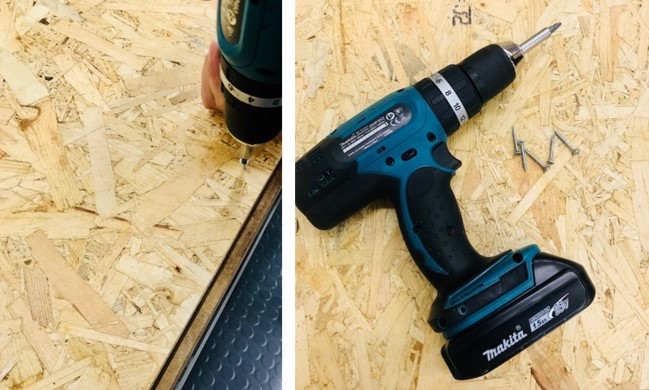
- I screwed the wood to the table of the machine.
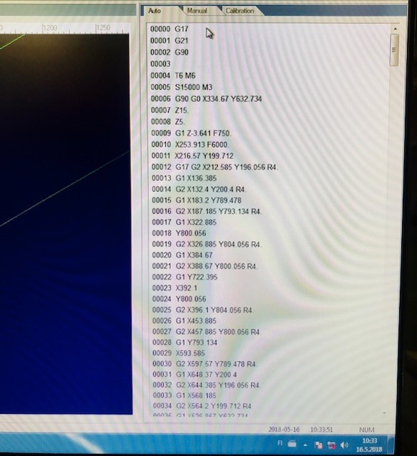
- Then I opened the .nc code that I previously prepared (explained in the previous section).
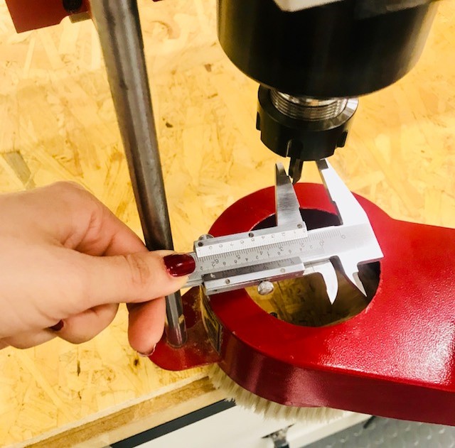
File > Open > Load > Then G code was shown on the screen - I measured the milling bit to choose one that is suitable based on the tool that I used in my file. I set it in my file to be 8mm-flat.
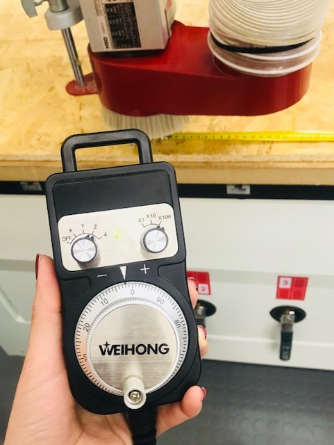
- Now it is time to set the origo. I used the hand wheel to bring the head in the location that I wanted for x and y.
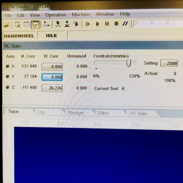
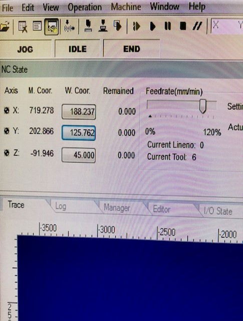
- Then under the NC State tab (which is located in the top left part of the main screen of the NcStudio program) I zeroed X and Y using W.Coor buttons.
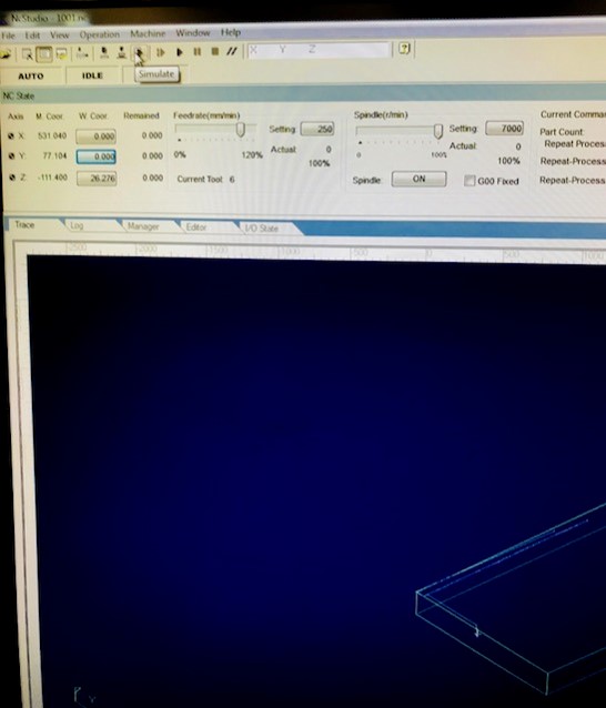
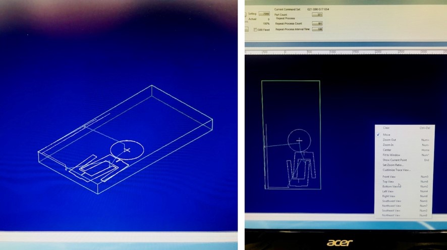
- Then in order to ensure that the design layout is as I expected, I played simulate functionality. And everything was ok. I also rightclicked on the simulation area and chose top view.
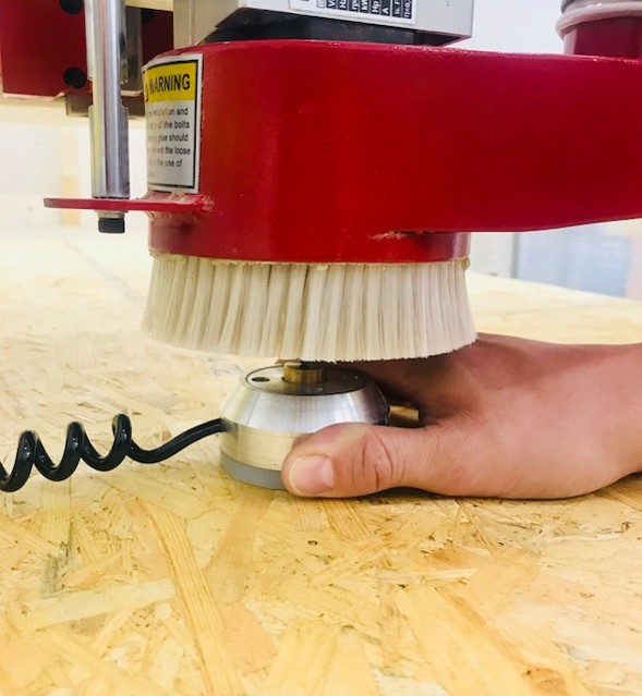
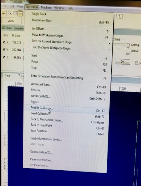
- Now it is time to set z axis. There are 2 ways: manually and automatically. I decided to do it in an automatic way. I placed the metal piece under the milling bit. Then in the software, I chose operations > mobile calibrations. Then The bit moved down toward the metal piece and detected the Z axis.
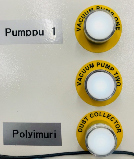
- Then I turned vcuum pump one, vacuum pump two and the dust collector of the machine, on. And I started the process.
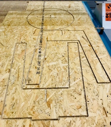
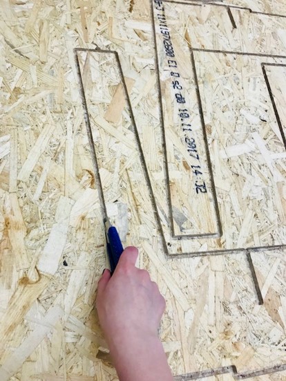
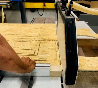
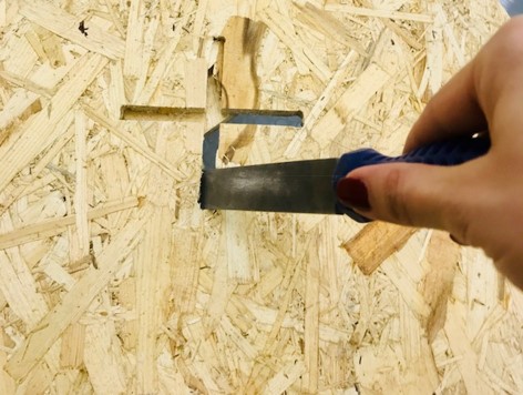
- Once it was done, since it did not cut through completely, as our instructor, Eino, suggested I started to remove the pieces using a cutter. But after 15 minutes I was feeling numb and pain in my wrist and I could cut only a very small piece.
- I called my friend to come and help me with this. And he also found it difficult. So we asked the machine's operator opinion regarding this and he suggested that we could use different machines there to make the task easier. So first we cut extra pieces around the design using a machine.
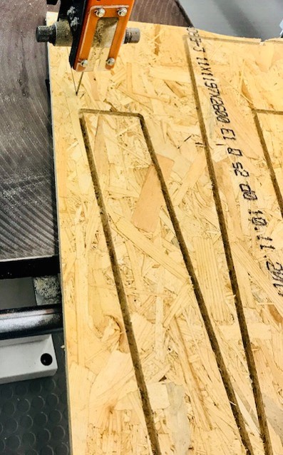
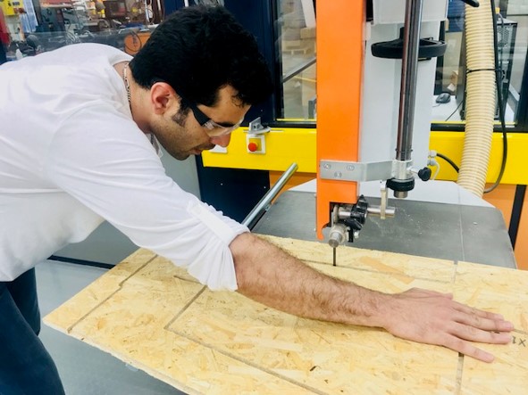
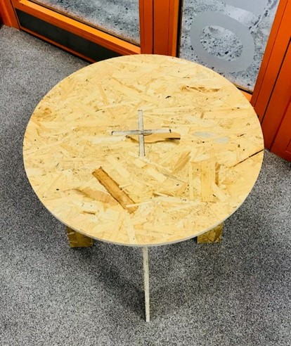
- Then we used the electronic saw machine to separate the 3 pieces, which I put them very close together for the sake of not wasting material. It was still a tedious and time consuming task.
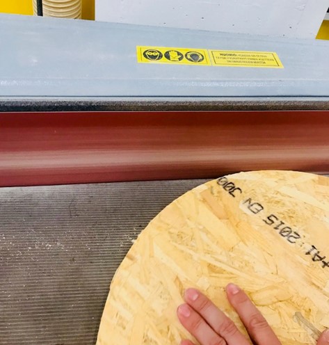
- Then we polished some parts using a machine.
- And also polishing some small parts using file.
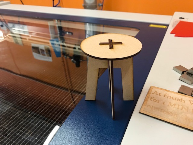
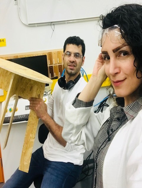
- Although I still have pain in my wrist, I am happy with the result!
Original Design Files
3D Design (.f3d)3D Design (.stl)
CAM Setting (.f3d)
CAM Setting (.stl)
.nc file