Week 4: Computer-Controlled Cutting
This week's tasks:
- Group assignment:
- characterize your lasercutter, making test part(s) that vary cutting settings and dimensions.
- Link to the Group Assignment Page
- Individual assignment:
- Cut something on the vinylcutter.
- Design, lasercut, and document a parametric press-fit construction kit, accounting for the lasercutter kerf, which can be assembled in multiple ways.
Vinylcutting
Challenges that I faced while vinylcutting:
- Generally speaking, working with vinyl cutting machine is easy in my opinion. The only challenge for me was figuring out how to adjust the sheet inside the machine when I had for example a small piece of sheet or a big roll of sheet. And I figured it out by experience.
- Secondly, once it happened that I was cutting a very detailed design and all around the design was exfoliating and actually I did not figure out what the problem was. I just repeated cutting and it was OK in the second time.
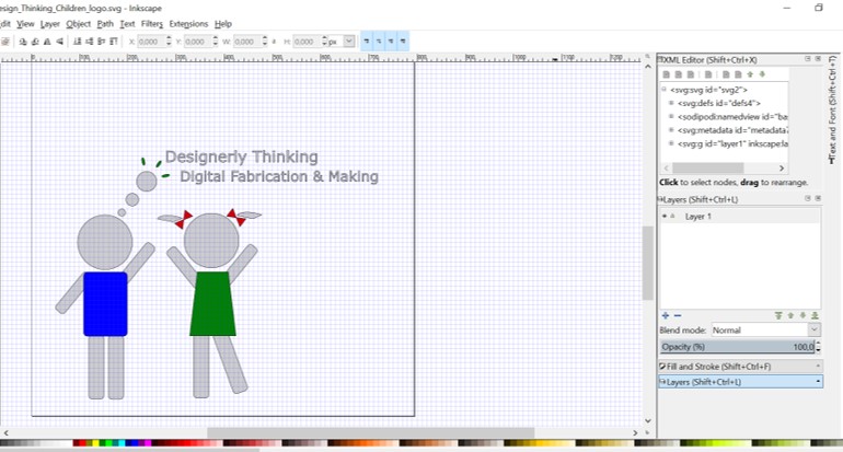
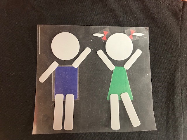
Since I wanted to have a colorful result, first I designed the whole idea, then I seperated all the colors and saved the items with the same color in a same file.
Considerations for less waste of material:
- Placing the design in the left bottom of the document.
- Or, resizing the document to approximately the same size as your design.
- It is easier if you draw a box around you design. Later on when you want to peel the design from the sheet, it will be easier and faster.
- Inkscape
- VinylCutting Machine
- Heating Print Press
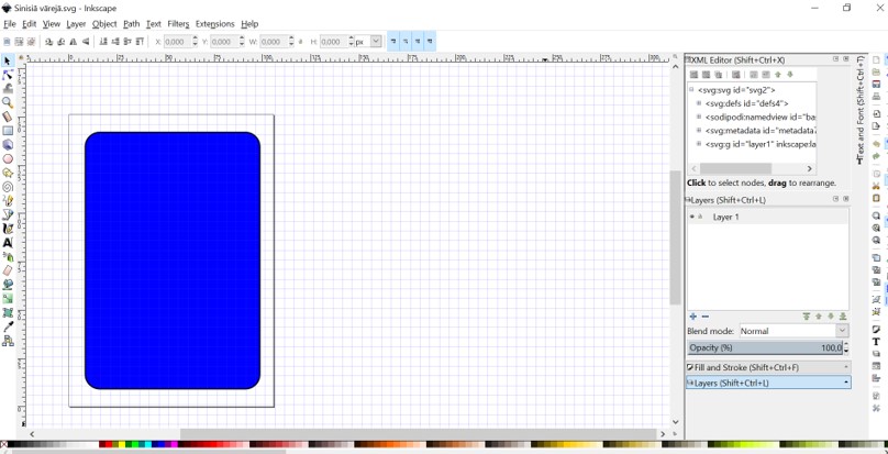
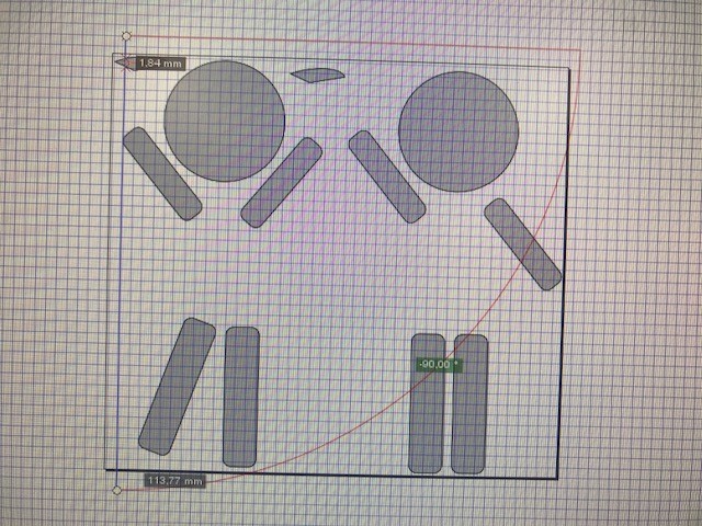
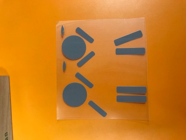
- I created my design idea in a single file..
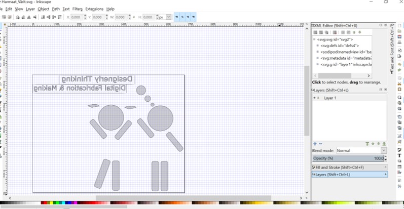
- I created a file for gray parts, I also reversed them.
- Red parts.
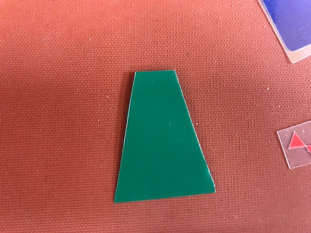
- Green parts.
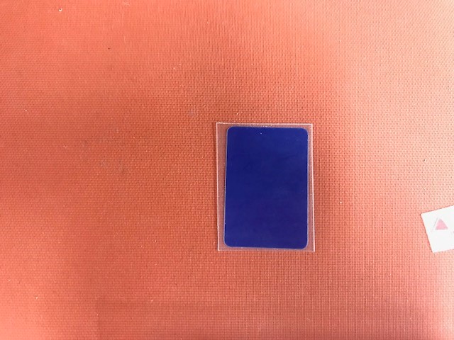
- Blue parts.
- Now all the colors are ready for vinylcutting.
- I explain how to use and how to set the vinylcutting machine that we have in fab lab Oulu in the next section. So in this section I focus on the process not on the machine.
- I cut each file with a specific color separately on the sheet with the same color.
- Cutting gray parts.
- I cut it from the other way around mistakingly. So I did it again. The shiny surface should be toward down.
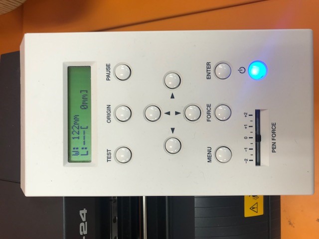
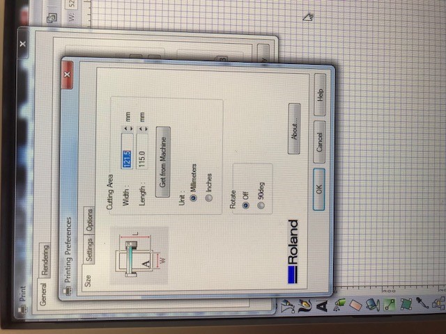
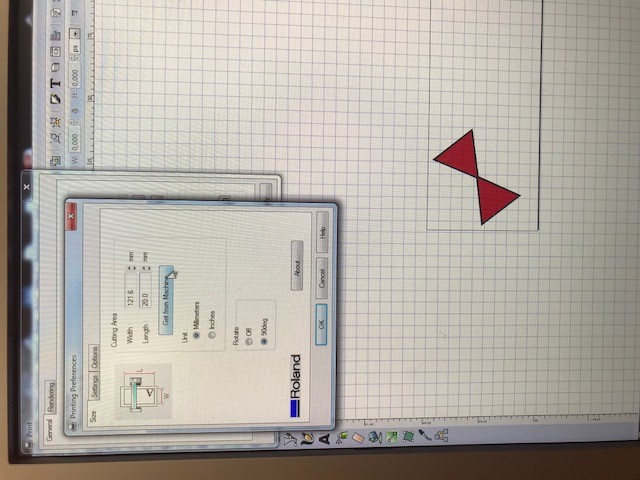
- Setting the edge by pressing the button with down arrow and selecting edge and then pressing enter. It says the width is 122mm.
- Then I opened the file in the computer with Inkscape and used Ruler tool to measure the height of my design.
- Then I pressed ctrl+p and chose the device and then to the preferences tab. Here I got the width from the machine and I entered the height by myself (I measured it in the previous step by ruler.)
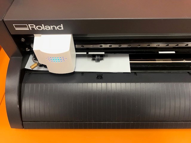
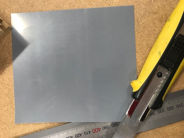
- I cut around the design with cutter to make a box around.
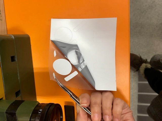
- I removed it with this tool as you see in the picture.
- And here is the result.
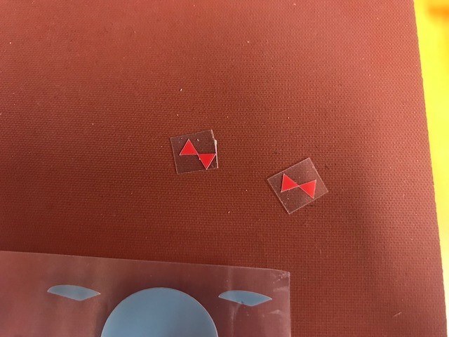
- Cutting red parts.
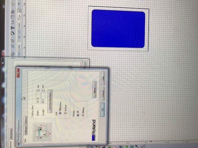
- Cutting blue parts.
- Cutting green parts. I cut this part by hand.
- I Oriented all parts on the Tshirt.
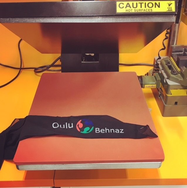
- I changed the orientation a bit since I wanted the gray part to be under the blue and green parts. First, I pressed the gray parts using heating machine. I forgot to take picture at this point. I also added a text to it later.
- Then I pressed blue, green and red parts.
- Here is the final result.
- I also did the same process to print another design on one of my scarfs.

Instructions for Working with RONALD GAMMA-1 GS-24 Vinyl Cutter in Fab Lab Oulu:
What is a vinyl cutting machine?
This blade is used to cut out shapes and letters from sheets of thin self-adhesive plastic (vinyl). Wikipedia
Image Resource: Screenshot from User's Manual

- Border stroke: 0,5 pt
- Separate different colors in different files.
- There are some white strips, which are kind of signs for placing the rollers in the right place. Rollers should be placed on the white ribbons.
- On which white strip should you set the pinch roller? It depends on the width of the sheet.
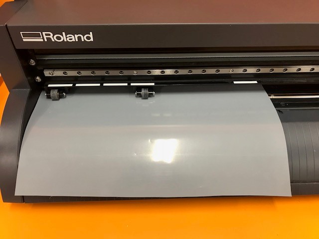
- Place the sheet inside the machine from the less slippery side.
- Lock it. Once I forgot to lock it and it was continuing to rolling nothing for 2,3 minutes.
- Take the edge using the operation panel. And press enter. It calculates the width of the sheet from the left pinch roller to the right pinch roller. Settings in the computer:
- Calculate the height of your design with ruler tool.
- Press print.
- Choose the device, that you are going to cut with.
- Preferences: Get from machine: It will takes the width of the sheet from the machine.
- Enter the height that you took with ruler tool.
- Rotate: off
- And ready to go.
Press-fit construction kit
Technology Used:- Inkscape
- Laser cutting
- Fusion 360
I found it very useful to design and make a paper stand with 2 legs. Becuase I sometimes print some articles and read them and most of the time I find it difficult and not easy for the neck to bend on the paper and for the hand to keep the paper all the time. So I thought I could make the plane of the stand like pieces of puzzle. In this way it is wasy to carry the stand everywhere with you (e.g. library, home, office). One just need to assemble the pieces easily and fast :-)
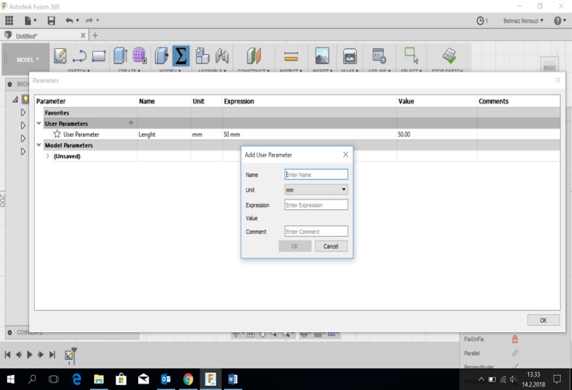
- In Fusion 360 > Modify > Change Parameters > user parameters > clicking on the + icon > specifying name, unit and value > OK
-
Defining parameters
Lenght: 50mm: the lenght of each piece
half_lenght: lenght/2: 20mm Kerf: the widht of the removed material when something is cut: 0.08mm.
material_tickness: 3mm: the tickness of MDF that I used.
slot width: 10mm: the width of each slot. slot depth: 10mm: the depth of each slot.
For those pieces with indent the slot width would be: slot_width - kerf: 9.92mm
For those pieces with indent I considered a parameter named "half_lenght_for_interior": 20.4mm
For those pieces with outdent the slot width would be: slot_width + kerf: 10.08mm
For those pieces with indent I considered a parameter named "half_lenght_for_exterior": 19.96mm

-
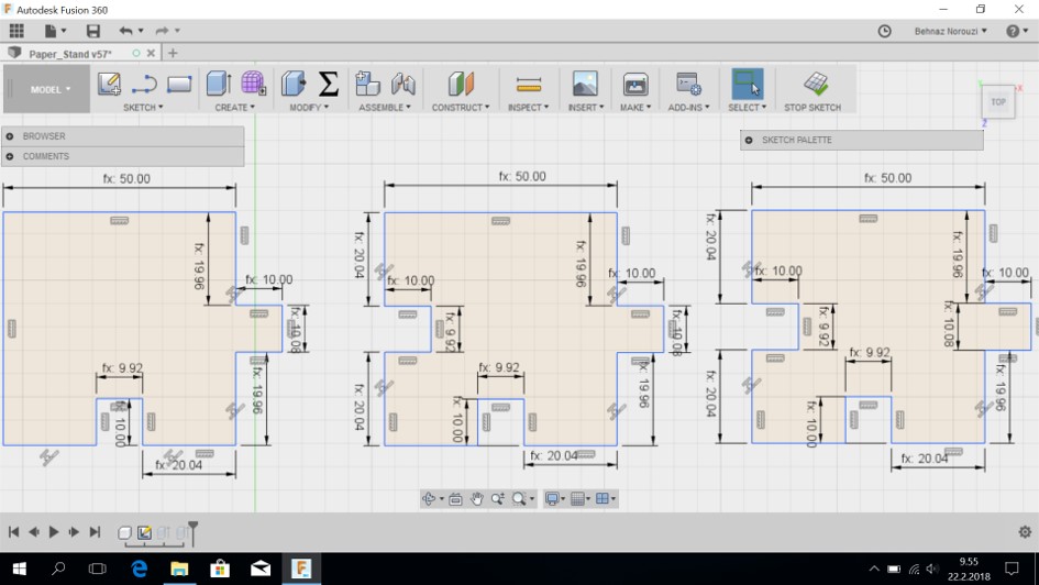
Designing different shapes that are needed.
After calculating and creating the parameters that I need for designing different shapes that I need, I started to draw the shapes. I had the overall of 15 pieces. 9 of the pieces had different shapes and I drew them individually and I copied and pasted the other similar ones. For drawing each shape, I used sketch > line. And then for applying the specific parameter (that I had previously created), to the drawn line, I used Sketch > Sketch Dimension. Here a box appears and asks for the value. Instead of inserting the value as a number, I started to type the name of one of the parameters that I had created before.
For example for the shape located in the right side of the screen that you see in the picture bellow, for the slot width I typed "slot_width - kerf". Slot width is 10mm and kerf is 0.08 mm. So slot_width minus kerf gave me the value of 9.92 mm for the width of the slot with indent. Each side of the shape has the value of 50 mm. So considering that in the shape that I have just explained as an example, I used the parameter "half_lenght_for_interior" with the value of 20.04 mm for 2 sides connected to the slot (slot is in the middle). So the overall lenght of the side would be 20.04 + 20.04 + 9.92 = 50 mm.
The same logic goes for the other pieces as well. In the following I provide some pictures demonstrating different shapes that I designed.


-
A holistic view of all the shapes

-
To export as pdf
file: new drawing: from design
-
It asks you to switch to modeling mode.

-
Here hit OK

-
Here change the scale to 1 to have the actual size of your design

-
And now output it as pdf

-
Then I imported the pdf file into Inkscape and set the border stroke style and finally laser cut it.
-
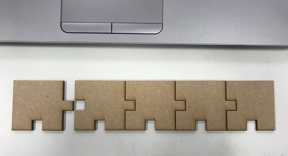
And this is the final result of the plane of the stand.


Some parts are still a bit loose for example the side parts, but the pieces in the center are tight enough. Yet I have not figured out what the reason is. I will try another time by changing the parameter for kerf and if it goes well I will design the legs of the stand later on.
- I changed the kerf size to 0.01 mm. Some pieces are tight enough and fit together perfectly. But I faced the same problem again. The left piece is loose although its size is the same as other pieces. So there might be a problem with the machine! I do not know.

Instructions for Using LASER CUTTING Device: EPILOG Laser Fusion 75 WATT in Fab Lab Oulu
Considerations:- Document type (for sending print order): PDF
- Stroke Style: 0,020 mm
- In order to prevent waisting material, place your design elements so close to each other and at the top left of the document.
- Compressor should be ON
- Air Cleaner should be ON
- One should always watch it when the laser cutting machine is working. There is a high possibility of fire every moment.
- Ctrl + p
- Choose the machine (printer)
- Check "Toldellin koko" (The true size)
- General: Job type:
- Raster: created with pixel-based program or captured with a camera or scanner. More common in jpg, gif and png. When using raster programs it is like you paint an image.
- Vector: created with vector software. When using a victor program, you draw the outline of the shapes.
- Combined: when it both cuts and engraves.
- Advanced:
-
Here you define the material or choose the saved ones: It depends what material you are going to choose, e.g. MDF 3 mm cut-les 2.0. --> Load --> OK (These are some saved settings for a starting point)
When you load the file and press OK, you will notice that in "General# tab the adjustments for the selected material are usually there (someone has tested and adjusted previously). -
I used the default setting for chosen material (MDF 3mm):
- Speed:how fast the laser moves throughout the material: 10%
- Power:the power of the laser beam: 80%
- Frequency:the frequency of the laser pulses: 20%
- Tulosta (print)
Find the other images and documentations related to this machine here (This link is also the source of the two following pictures)
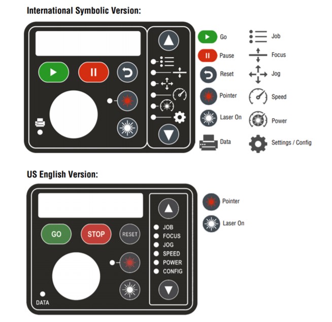
- "Jog" feature: On the fusion control panel, the jog feature is used for moving the laser and setting the start point of the engraving activity.
- Select "jog", using up/down buttons.
- Use the joystick to move the laser around the table.
- When it is in the desired and correct place, push the joystick inside, to set the jog.
- "focus feature": It is used for setting the table to a correct height for engraving.
- Focus has 2 speeds. "2 arrows" is for the high speed. And "1 arrow" for low speed. It is better to choose "1 arrow", in order to achieve more convenient focus setting.
- Place the aluminum piece (2 inch) inside the machine.
- Set the table height using up and down of joystick. When the surface of the material encounters the head of the aluminum piece, the height of the table is well adjusted.
- After achieving the desirable and correct height, Push the joystick inside to set the focus.
- Caution: bring out the piece after you set the height of the table.
- "Job Feature": For choosing the job in your laser system.
- Use up/down buttons on the fusion control panel to select "job".
- Use the joystick up/down to go through the jobs listed, until you find the job that you want.
- Press the "start" button on the fusion control panel.
Original Design Files
3D PiecesPDF file of the Pieces
Files for Vinylcutting of my Design