Electronics production
- The assignment is to make the FAB (tiny)ISP in-crcuit programmer
- connect arduino to my computer and upload arduino as Ip Sketch
- connect my ISP to arduino using ISP communication i open terminal and start typing this command
sudo apt-get install flex byacc bison gcc libusb-dev avrdude
sudo apt-get install gcc-avr
sudo apt-get install avr-libc
sudo apt-get install libc6-dev
cd ~/Desktop
wget http://academy.cba.mit.edu/classes/embedded_programming/firmware.zip
nano Makefile
in terminal
make clean
rm -f main.hex main.lst main.obj main.cof main.list main.map main.eep.hex main.elf *.o usbdrv/*.o main.s usbdrv/oddebug.s usbdrv/usbdrv.s
then type
make hex
avr-gcc -Wall -Os -DF_CPU=20000000	 -Iusbdrv -I. -DDEBUG_LEVEL=0 -mmcu=attiny44 -c usbdrv/usbdrv.c -o usbdrv/usbdrv.o
avr-gcc -Wall -Os -DF_CPU=20000000	 -Iusbdrv -I. -DDEBUG_LEVEL=0 -mmcu=attiny44 -x assembler-with-cpp -c usbdrv/usbdrvasm.S -o usbdrv/usbdrvasm.o
avr-gcc -Wall -Os -DF_CPU=20000000	 -Iusbdrv -I. -DDEBUG_LEVEL=0 -mmcu=attiny44 -c usbdrv/oddebug.c -o usbdrv/oddebug.o
avr-gcc -Wall -Os -DF_CPU=20000000	 -Iusbdrv -I. -DDEBUG_LEVEL=0 -mmcu=attiny44 -c main.c -o main.o
main.c:88:13: warning: always_inline function might not be inlinable [-Wattributes]
 static void delay ( void )
             ^
avr-gcc -Wall -Os -DF_CPU=20000000	 -Iusbdrv -I. -DDEBUG_LEVEL=0 -mmcu=attiny44 -o main.elf usbdrv/usbdrv.o usbdrv/usbdrvasm.o usbdrv/oddebug.o main.o
rm -f main.hex main.eep.hex
avr-objcopy -j .text -j .data -O ihex main.elf main.hex
avr-size main.hex
   text	   data	    bss	    dec	    hex	filename
      0	   1986	      0	   1986	    7c2	main.hex
then type
make fuse
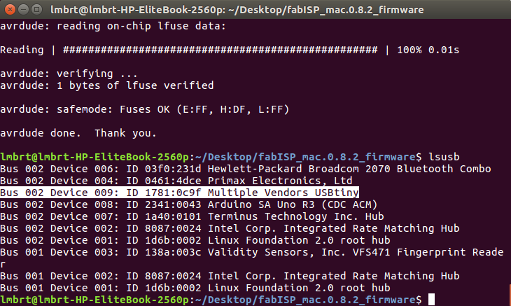
avrdude -c stk500v1 -b19200 -P /dev/ttyACM0 -p attiny44 -U hfuse:w:0xDF:m -U lfuse:w:0xFF:m

avrdude: AVR device initialized and ready to accept instructions

Reading | ################################################## | 100% 0.02s

avrdude: Device signature = 0x1e9207 (probably t44)
avrdude: reading input file "0xDF"
avrdude: writing hfuse (1 bytes):

Writing | ################################################## | 100% 0.01s

avrdude: 1 bytes of hfuse written
avrdude: verifying hfuse memory against 0xDF:
avrdude: load data hfuse data from input file 0xDF:
avrdude: input file 0xDF contains 1 bytes
avrdude: reading on-chip hfuse data:

Reading | ################################################## | 100% 0.01s

avrdude: verifying ...
avrdude: 1 bytes of hfuse verified
avrdude: reading input file "0xFF"
avrdude: writing lfuse (1 bytes):

Writing | ################################################## | 100% 0.02s

avrdude: 1 bytes of lfuse written
avrdude: verifying lfuse memory against 0xFF:
avrdude: load data lfuse data from input file 0xFF:
avrdude: input file 0xFF contains 1 bytes
avrdude: reading on-chip lfuse data:

Reading | ################################################## | 100% 0.01s

avrdude: verifying ...
avrdude: 1 bytes of lfuse verified

avrdude: safemode: Fuses OK (E:FF, H:DF, L:FF)

avrdude done.  Thank you.
then type
make program
avrdude -c stk500v1 -b19200 -P /dev/ttyACM0 -p attiny44 -U flash:w:main.hex:i avrdude: AVR device initialized and ready to accept instructions Reading | ################################################## | 100% 0.02s avrdude: Device signature = 0x1e9207 (probably t44) avrdude: NOTE: "flash" memory has been specified, an erase cycle will be performed To disable this feature, specify the -D option. avrdude: erasing chip avrdude: reading input file "main.hex" avrdude: writing flash (1986 bytes): Writing | ################################################## | 100% 2.88s avrdude: 1986 bytes of flash written avrdude: verifying flash memory against main.hex: avrdude: load data flash data from input file main.hex: avrdude: input file main.hex contains 1986 bytes avrdude: reading on-chip flash data: Reading | ################################################## | 100% 1.45s avrdude: verifying ... avrdude: 1986 bytes of flash verified avrdude: safemode: Fuses OK (E:FF, H:DF, L:FF) avrdude done. Thank you. avrdude -c stk500v1 -b19200 -P /dev/ttyACM0 -p attiny44 -U hfuse:w:0xDF:m -U lfuse:w:0xFF:m avrdude: AVR device initialized and ready to accept instructions Reading | ################################################## | 100% 0.02s avrdude: Device signature = 0x1e9207 (probably t44) avrdude: reading input file "0xDF" avrdude: writing hfuse (1 bytes): Writing | ################################################## | 100% 0.01s avrdude: 1 bytes of hfuse written avrdude: verifying hfuse memory against 0xDF: avrdude: load data hfuse data from input file 0xDF: avrdude: input file 0xDF contains 1 bytes avrdude: reading on-chip hfuse data: Reading | ################################################## | 100% 0.01s avrdude: verifying ... avrdude: 1 bytes of hfuse verified avrdude: reading input file "0xFF" avrdude: writing lfuse (1 bytes): Writing | ################################################## | 100% 0.01s avrdude: 1 bytes of lfuse written avrdude: verifying lfuse memory against 0xFF: avrdude: load data lfuse data from input file 0xFF: avrdude: input file 0xFF contains 1 bytes avrdude: reading on-chip lfuse data: Reading | ################################################## | 100% 0.01s avrdude: verifying ... avrdude: 1 bytes of lfuse verified avrdude: safemode: Fuses OK (E:FF, H:DF, L:FF) avrdude done. Thank you.lsusb
and i find this name in devices connected to my computer this means that my ISP is working fine
Bus 002 Device 004: ID 1781:0c9f Multiple Vendors USBtiny
- FabISP
- modified firmware
FABISP

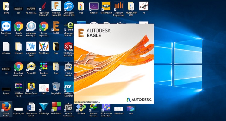
I downloaded a rondomly usbtiny circuit based on ATtiny44 and 45 i tried to understand how the circuit works with that attiny lower speed microcontrollers and finaly i buid my circuit in Eagle Autodesk


Fab modules
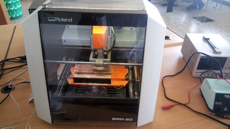
After designing and exporting our design we need to provide the (*.rml) file which will be used by our Roland monofab SRM 20 in milling process.
Generating (*.rml) file
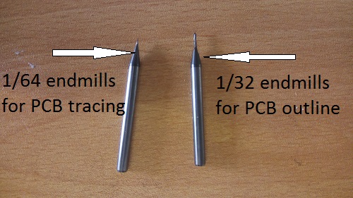
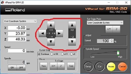
any web brower will work here just go to fabmodules website then click on Image and browse where your exported png fine has been saved, after immage has been opened click on output Format then click on Roland mill(.rml) then click on process then choose pcb traces(1/64) for circuit milling, after choosing thr process then choose output mashine in fiels located on left side of the fabmodules web on my side i choose to use SRM-20 set x0(mm); y0(mm); z0(mm);to 0 this means the mashine is going to start from the orgin point you set on your milling mashine exactly.
then under process pannel click on calculate in order to generate rml file before saving the rml file chech if all connection has been removed if not try to export the image again but now use high resolution than previous


set up monofab SRM-20 and milling
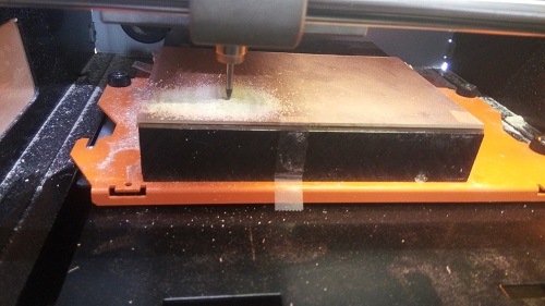
you have to be carefull on this step otherwise you may break the endmills so be care full
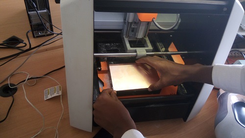
First atach double sided tape on bottom of your pcb and then overlap it to the base of mashine chech well if the pcb if fixed because the PCB must no move it has to be well fixed on a plate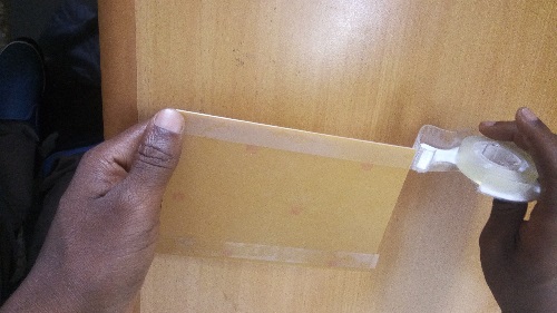


soldering,hero shot and programing
again be care full on this step on active components (zener,LED,ATtiny) you must follow they orintation cannection on board like all chips pin one is in parallel with a dot upward on it, this image was taken under digital microscope in order to know the polarites of LED


programing
 my hardest part i faced in this fabacademy is this one after making my board i tried to program it by usinG window 10 and it fail, after 2 days of testing and fail i moved to lunix and at the beginning i want to instal dual boot on my PC. But in case of making a partition i made a mistake and i erase my whole pc files (it was my first time to install lunix OS in Pc)i instralled lubuntu os and it crush before completing i shift to kali and the same it didn't get installed ony my pc after one more day i fund elementary OS is also lunix version i like it outlike but it didn't succed in programing my Board so i decide to reinstall my win10 for other uses and finaly i fund ubuntu 16 and now it working fine with my ISP
On programing i follow this instruction
this is how i did:
my hardest part i faced in this fabacademy is this one after making my board i tried to program it by usinG window 10 and it fail, after 2 days of testing and fail i moved to lunix and at the beginning i want to instal dual boot on my PC. But in case of making a partition i made a mistake and i erase my whole pc files (it was my first time to install lunix OS in Pc)i instralled lubuntu os and it crush before completing i shift to kali and the same it didn't get installed ony my pc after one more day i fund elementary OS is also lunix version i like it outlike but it didn't succed in programing my Board so i decide to reinstall my win10 for other uses and finaly i fund ubuntu 16 and now it working fine with my ISP
On programing i follow this instruction
this is how i did:

after i move to desktop by typing
then download firmware froam FabAcademy repository by typing
unzip the downloaded firmware
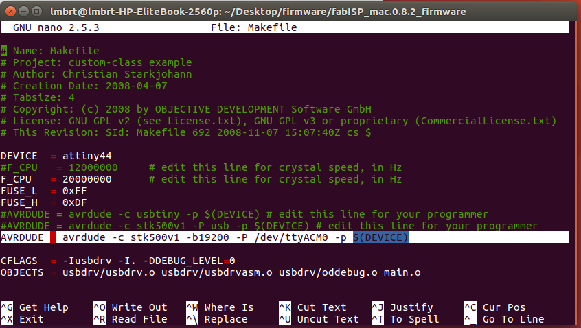
I have to edit firmware according to my programer
am using arduino as isp to do that i typein new opened windows i comment all two line for AVR and USBTiny programer and i write a new line like this
AVRDUDE = avrdude -c stk500v1 -b19200 -P /dev/ttyACM0 -p $(DEVICE)then CTRL+SHIFT+X keys to exit nano Makefile
 then i continue by typing
I got a message
I got a message
I got a message
I got a message
.JPG) every thing seems to be fine I am done with ISP programing now i have to check if my ISP is being recognized by my Computer i did this by typing
every thing seems to be fine I am done with ISP programing now i have to check if my ISP is being recognized by my Computer i did this by typing
 After checking every thing i upload the blinking shetck to my arduino uno using my Fabbed ISP
