NETWORKING AND COMMUNICATIONS
- Demonstrate workflows used in network design and construction
- Implement and interpret networking protocols
i designed two board with nRF24L01 transciever modules to link them the board i designed used atmga 238P microcontroller
Board Design

 i made this board for this assignment and for for interface in order to save the resources the reason why i used this modules is that this nRF24L01 transcieve modules consume low power that power consumed by led and it use SPI protocal in it communition where you have to decide the channel has to play as transimmision channel and which one can be used as reception channel, other thing this modules use the some band width as RC communication which I am using now in my project so in this can help in case i want to make my own transimmission system this is small introduction about nRF24L01
The nRF24L01 is a highly integrated, ultra low power (ULP) 2Mbps RF transceiver IC for the 2.4GHz ISM (Industrial, Scientific and Medical) band. With peak RX/TX currents lower than 14mA, a sub μA power down mode, advanced power management, and a 1.9 to 3.6V supply range, the nRF24L01 provides a true ULP solution enabling months to years of battery lifetime when running on coin cells or AA/AAA batteries, this modules can help in case you are designing a small IoT because one modules can send command to other 6 modules without needing of server
now the most part of this assignment to think on how you can send some data via network so now in order to learm learn much more about this modules and to know How they work i designed a small network of 2 board having two Led each so one is a master and the second is slave master is connected to my computer where i send led controll command the the slave is connected any where not far to 100m so i can turn ON and OFF all led using one board(master) after soldering my board i figured out that i forget to add voltage regulator for nRF24L01 because those modules use only supply voltage ranges from1.9v to 3.6v
so i troubleshoot and look the way i can solder the 3.3v voltage regulator on board. like this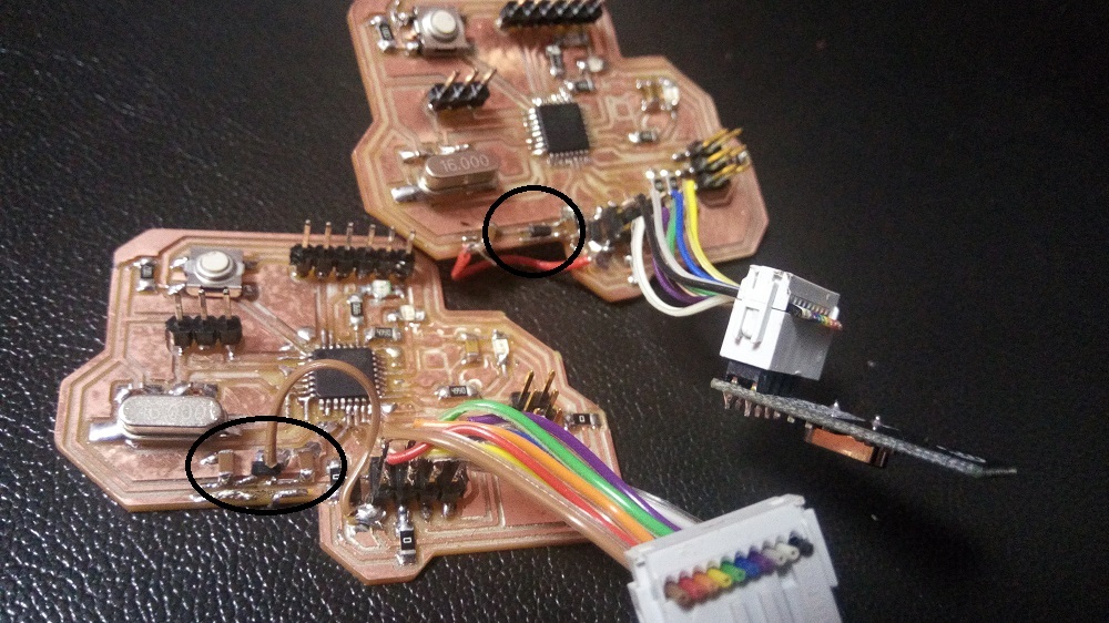

Embedded Programing
i upload the following shetch in the master board
#include#include "RF24.h" RF24 radio(9, 10); int led = A2; //declare LED onnected pin on my board int led1 = A3; //declare LED1 onnected pin on my board const uint64_t pipes[2] = { 0xF0F0F0F000LL, 0xF0F0F0F0FFLL}; //defining two pipe where one is going to be used as reading pipe and other pipe as writting pipe this nRF23L01 can not use one pipe for both writting and reading like other modules like bluetooth modules /// initializing the program void setup(){ Serial.begin(9600); /// starting serial communication where all command will be send from (you can use bluetooth or serial monitor radio.begin(); /// starting radio communication to link all board together radio.setDataRate(RF24_250KBPS); /// set radio communication DataRate to 250 kBs per sec radio.setChannel(100); /// set radio communication channel you can use up to 124 channel for communication radio.setRetries(15,15); radio.openWritingPipe(pipes[1]); /// opening writting pipe where master board will send comand throught radio.openReadingPipe(1, pipes[0]); /// opening reading pipe where master board will receive feedback from slave board radio.startListening(); pinMode(led1, OUTPUT); /// set LED1 as output pinMode(led, OUTPUT); /// set LED as output } void loop(){ if(Serial.available()){ char data[32] = ""; byte i = 0; while(Serial.available()){ data[i] = Serial.read(); i++; delay(2); /// in case there is any signal from serial communication my board start reading that data with interval of 2 milliseconds } data[i] = 0; radio.stopListening(); radio.write(&data, 32); /// send all data reecieved from serial communication over radio link radio.startListening(); if (data[0] == '1') digitalWrite(led, HIGH); /// if data received is equal to 1 turn LED ON) if (data[0] == '2') digitalWrite(led, LOW); /// if data received is equal to 0 turn LED OFF) if (data[0] == '3') digitalWrite(led1, HIGH); /// if data received is equal to 3 turn LED1 ON) if (data[0] == '4') digitalWrite(led1, LOW); /// if data received is equal to 4 turn LED1 OFF) if (data[0] == '5') digitalWrite(led, HIGH), delay(1000),digitalWrite(led, LOW); /// if data received is equal to 5 turn LED ON for 1 sec and turn it OFF back) } if(radio.available()){ char data[32] = ""; radio.read(&data, 32); Serial.println(data); // printing data from slave board over serial monitor or serial communication } }
for the slave i uploaded the following sketch:
//SCK -> 13 //MISO -> 12 //MOSI -> 11 //CSN -> 10 //CE -> 9 #include#include "RF24.h" RF24 radio(9, 10); /// set modules vs board communication pin int led = A2; //declare LED onnected pin on my board int led1 = A3; //declare LED1 onnected pin on my board const uint64_t pipes[2] = { 0xF0F0F0F000LL, 0xF0F0F0F0FFLL}; //defining two pipe where one is going to be used as reading pipe and other pipe as writting pipe this nRF23L01 can not use one pipe for both writting and reading like other modules like bluetooth modules /// initializing the program void setup(){ radio.begin(); /// starting radio communication to link all board together radio.setDataRate(RF24_250KBPS); /// set radio communication DataRate to 250 kBs per sec radio.setChannel(100); /// set radio communication channel you can use up to 124 channel for communication radio.setRetries(15,15); radio.openWritingPipe(pipes[0]); /// opening writting pipe whereslave board will send feedback to master board throught radio.openReadingPipe(1, pipes[1]); /// opening reading pipe where slave will listern all comand from the master board radio.startListening(); pinMode(led1, OUTPUT); /// set LED1 as output pinMode(led, OUTPUT); /// set LED as output } void loop(){ if(radio.available()){ char data[32] = ""; radio.read(&data, 32); if (data[0] == '1') digitalWrite(led, HIGH); if (data[0] == '2') digitalWrite(led, LOW); if (data[0] == '3') digitalWrite(led1, HIGH); if (data[0] == '4') digitalWrite(led1, LOW); if (data[0] == '5') digitalWrite(led, HIGH), delay(1000),digitalWrite(led, LOW); radio.stopListening(); radio.write(&data, 32); //writing back the value readed from radio link to master board radio.startListening(); } } }
from this code here there is a small video i made on
after completing all testing
i decided to edit my board for any one want to use buy adding 3.3 v regulator in order to provide stable and prevent nRF24L01 where the supply voltage need to be in l=ramge of 1.9v to 3.6 v