INPUT DEVICE
- Demonstrate workflows used in circuit board design and fabrication
- Implement and interpret programming protocols
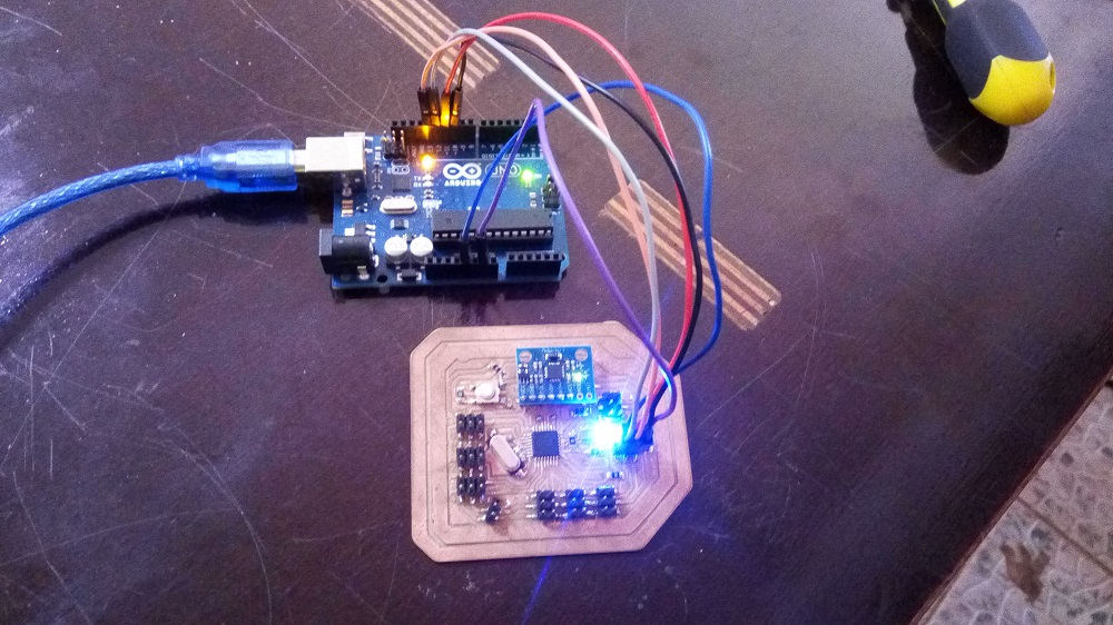
I decided to organize the two exercise "input" and "output" and my project controller together, to make a board I will use in a project.This week I'll make a first version of the board,using atmega 328p, MPU 6050 (gyroscope and ACCELEROMETER) and the other pin i will let them connected to pin header for preview layout of my flighter controller so that i can ready the value RC receiver
Board Design

Download Boards files
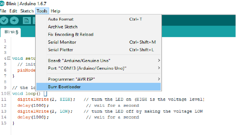
BURNING BOOTLOADER ON THE CHIP


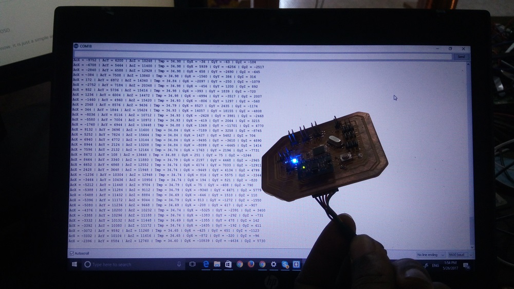
Reading Accelerometer and Gyroscope values
to ready the values of Gryoscope and i used the following code#includeconst int MPU_addr=0x68; // I2C address of the MPU-6050 int16_t AcX,AcY,AcZ,Tmp,GyX,GyY,GyZ; void setup(){ Wire.begin(); Wire.beginTransmission(MPU_addr); Wire.write(0x6B); // PWR_MGMT_1 register Wire.write(0); // set to zero (wakes up the MPU-6050) Wire.endTransmission(true); Serial.begin(9600); } void loop(){ Wire.beginTransmission(MPU_addr); Wire.write(0x3B); // starting with register 0x3B (ACCEL_XOUT_H) Wire.endTransmission(false); Wire.requestFrom(MPU_addr,14,true); // request a total of 14 registers AcX=Wire.read()<<8|Wire.read(); // 0x3B (ACCEL_XOUT_H) & 0x3C (ACCEL_XOUT_L) AcY=Wire.read()<<8|Wire.read(); // 0x3D (ACCEL_YOUT_H) & 0x3E (ACCEL_YOUT_L) AcZ=Wire.read()<<8|Wire.read(); // 0x3F (ACCEL_ZOUT_H) & 0x40 (ACCEL_ZOUT_L) Tmp=Wire.read()<<8|Wire.read(); // 0x41 (TEMP_OUT_H) & 0x42 (TEMP_OUT_L) GyX=Wire.read()<<8|Wire.read(); // 0x43 (GYRO_XOUT_H) & 0x44 (GYRO_XOUT_L) GyY=Wire.read()<<8|Wire.read(); // 0x45 (GYRO_YOUT_H) & 0x46 (GYRO_YOUT_L) GyZ=Wire.read()<<8|Wire.read(); // 0x47 (GYRO_ZOUT_H) & 0x48 (GYRO_ZOUT_L) Serial.print("AcX = "); Serial.print(AcX); Serial.print(" | AcY = "); Serial.print(AcY); Serial.print(" | AcZ = "); Serial.print(AcZ); Serial.print(" | Tmp = "); Serial.print(Tmp/340.00+36.53); //equation for temperature in degrees C from datasheet Serial.print(" | GyX = "); Serial.print(GyX); Serial.print(" | GyY = "); Serial.print(GyY); Serial.print(" | GyZ = "); Serial.println(GyZ); delay(333); }
conclusion
my Board is reading input value well and i hope it will work for my projectDownload files
MPU 6050 CODEPCB BOARD