[WEEK04] Erectronics Production
What I made
I made cicuit board with milling machine and manual soldering.
1. PCB fabrication
I made PCB boards for FabISP with milling machine and fiber laser cutter. FabISP is a programmer for AVR microcontrollers designed by various makers. So I tried to make them of different versions on each machine.
| Milling machine | hello.ISP.44 |
| Fiber Laser cutter | hello.ISP.44.res |
1.1 Milling Machine
The machine that I used was Roland MDX-40.

At first, I shaped the surface of a follow board to level the platform. And then, I set the PCB material "FR1" upon it.

I used the following endmills.
- trase:endmill 60°
- interior:hatching endmill 1.27mm

I created NC code file with Fab Module.
| input format | file name | output format | process |
| image(.png) | hello.ISP.44.traces.png | Roland mill(.rml) | PCB traces(1/64) |
| image(.png) | hello.ISP.44.interior.png | Roland mill(.rml) | PCB outline(1/32) |
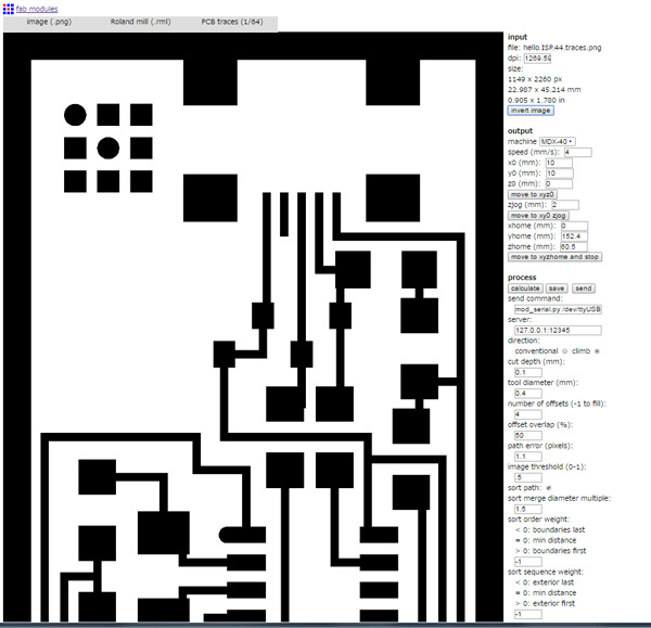
The origin and the number of rotation ware set on Roland Vpanel for MDX-40.

I milled the trace. And then I cutout the outline after changing the mills .


Download
hello.ISP.44.trace.rml: Download the file
hello.ISP.44.interior.rml: Download the file
1.2 Fiber Laser Cutter
I tried to make PCB board of another design with another way.The laser cutter I used was trotec speedy 100 flexx. This model can switch between CO2 lazer and fiber laser. So I milled the trace with fiber lazer mode and cutout the outline with CO2 lazer mode. At first, I modeled 2D data for lazercutting based on "hello.ISP.44.res.traces.png" with Illustrator. The settings was as below.
- Black/Engrave/fiber laser
- Red/Cutting/CO2 laser


I set the resolution of the raster data for 600dpi and engraved the board. But, some areas were short-circuit. So I changed it to 1000dpi and retried. The next one was successful.

 I checked wheather there was any short circuit and any lines were connected using digital multimeter.

Download
hello.ISP.44.res.traces.ai:
Download the file
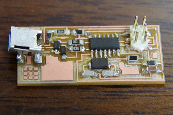
2. Assembly
I soldered the following components to the PCB board using a soldering iron. It was the first time soldering surface mount parts. So I desoldered with desolder brade many times. Though the circuit had been completed, the soldered part was not shine and smooth. I need to practice more.
| Part name | Quantity |
| ATTiny 44 microcontroller | 1 |
| Capacitor 1uF | 1 |
| Capacitor 10 pF | 2 |
| Resistor 100 ohm | 2 |
| 1 Resistor 499 ohm | 1 |
| Resistor 1K ohm | 1 |
| Resistor 10K | 1 |
| 6 pin header | 1 |
| mini USB connector | 1 |
| 0 ohm resistors | 2 |
| Cystal 20MHz | 1 |
| Zener Diode 3.3 V | 2 |
3. Programming
I tried to program to the circuit above to make it FabISP. I used Mac on this process. At first, I Downloaded and Installed the following software.
- CrossPack for AVRR Development "CrossPack-AVR-20131216.dmg"
- Xcode (This software had been already installed.)
cd ~/Desktop/
Unzip the firmware.zip directory on my desktop.
unzip fabISP_mac.0.8.2_firmware.zip
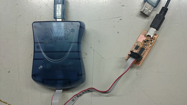
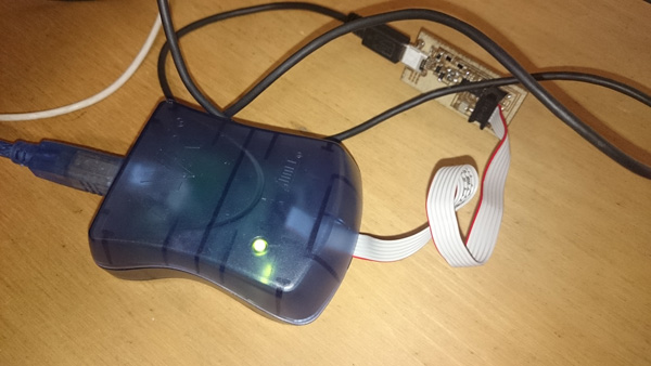
I plugged the mini USB connector for the FabISP into my computer and the AVRISPmk2 into the 6-pin programming header. And I made sure that the green light was lighten.
 Then I programmed the board in accordance with the instruction.
cd Desktop/fabISP_mac.0.8.2_firmware
make clean

make hex
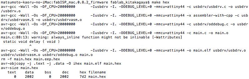
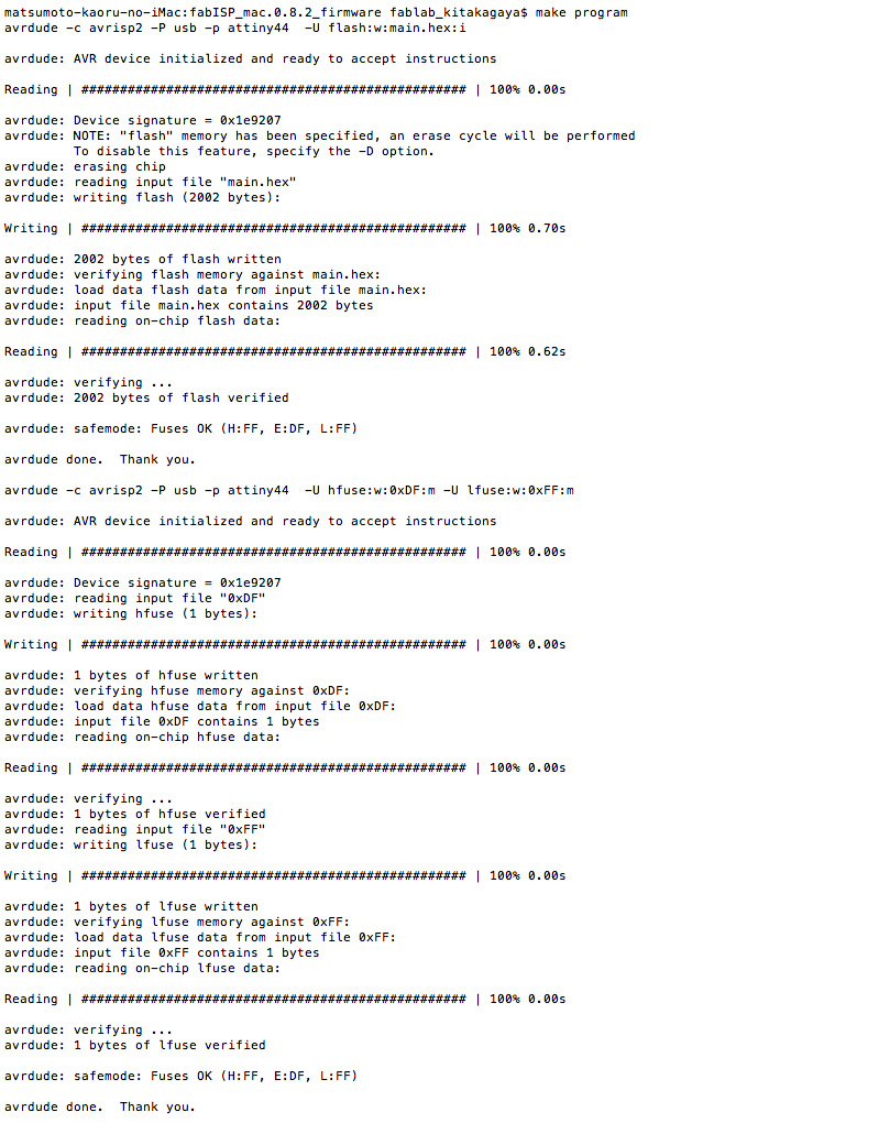
make fuse
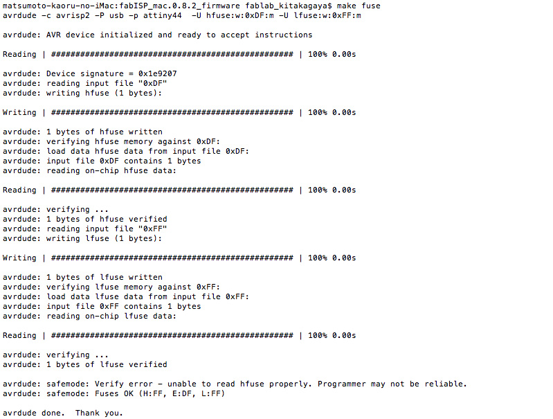
make program
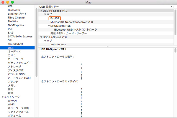
It seemed to be successful. So I checked the System Profiler and verifed my FabISP was working correctly.
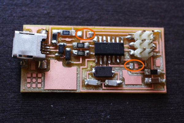
At last, I removed two 0ohm resisters to use this board as a programmer.
4. Additional challenge
I tried to program another board using my FabISP.
Assembly
I assemled the board made with a fiber laser cutter (20MHz resonator version)

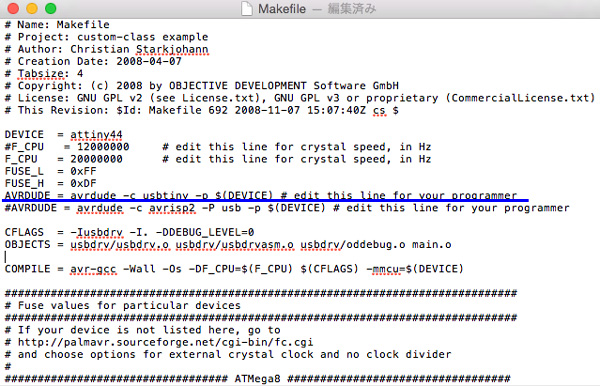
Edit Makefile
I editted the makefile because I was going to use FabISP as a programmer. - Remove the "#" in front of the line with "usbtiny" in it - Add a "#" to beginning the line with the "avrisp2" in it to comment it out.
Programming
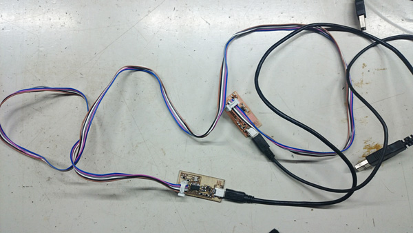
I connect my FabISP to the 6-pin programming header on the board.Each board connect to my computer with mini USB cable.
I programmed it in the same way as the previous. The same message displayed, so I thought it was sucessful. But "FabISP" wasn't listed in the system profiler. The computer doesn't recognize it as a FabISP or even any other devices.
Debugging
At first, I checked that there was no short circuit with digital multimeter. There seemed to be no problem. And I tried to program the board using AVRISP. When I connected them to the computer, the yellow light was lighten.
So I think there is a defect somewhere. Certainly, many solder joints doesn't look shiny and smooth.But I still can't identify where the problem is. It is a remaining task.