The logic inside the PastEtruder
As the electronics was a little bit bigger, the code is also a bit longer...
The PastEdruder is programed with MPLAB-X and the XC8 compiler, the same combination i used for
the Fab-Pic. In fact it is the same controller...
First make some configuration-settings and define some names for the pins to make the code more readable:
              #define RS PORTCbits.RC2

              #define EN PORTCbits.RC3

              #define D4 PORTCbits.RC4

              #define D5 PORTCbits.RC5

              #define D6 PORTCbits.RC6

              #define D7 PORTCbits.RC7


              #define heater_1 PORTCbits.RC0

              #define heater_2 PORTCbits.RC1

              #define stepper_dir PORTAbits.RA3

              #define stepper_step PORTAbits.RA5

              #define spritze_dir PORTBbits.RB7

              #define spritze_pwm PORTBbits.RB6


              #define btn_up PORTBbits.RB5

              #define btn_down PORTBbits.RB4

              #define btn_left PORTBbits.RB3

              #define btn_right PORTBbits.RB2


              #define external_dir PORTBbits.RB1

              #define external_step PORTBbits.RB0


              #pragma config FOSC = HS1    //extern oszilator 4-16mhz

              #pragma config PLLCFG = ON   //PLL enable, CPU=32 MHz

              #pragma config PWRTEN = ON   //PowerOnTimer on

              #pragma config WDTEN = OFF   //Watchdog Timer off

              #pragma config XINST = OFF   //Extended Instruction Set off, no support by free compiler

              #pragma config SOSCSEL = DIG //PORTC.0 and PORTC.1 digital I/O, not second oszilator
As you can see, almost all pins are used. RS, EN, D4 to D7 are used for the display.
After this we define some globale variables:
              int temp_1_ist, temp_2_ist;

              int temp_1_soll = 2045;

              int temp_2_soll = 2045;

int motor_current_ist;

int motor_current_soll = 0;

int temp;

int menue = 0;

int stepper_manual = 0;

int lcd_in_progress = 0;

float temp_1_ist_display = 20;

float temp_2_ist_display = 20;

int temp_1_soll_display = 20;

int temp_2_soll_display = 20;
Folowed by two subroutines: temp_read and temp_check.
temp_read just starts the ADCs and read in the values for both heaters and the motor-current:
  void temp_read(void)

  {

      ADCON0 = 0b00000001;     //Select AD-Channel 0

      ConvertADC();     //start AD-Conversion

      while(BusyADC());     //wait for conversion to finish

      temp_1_ist = ((ADRESH)<<8)|(ADRESL);    //read in the result


      ADCON0 = 0b00000101;     //Select AD-Channel 1

      ConvertADC();     //start AD-Conversion

      while(BusyADC());     //wait for conversion to finish

      temp_2_ist = ((ADRESH)<<8)|(ADRESL);    //read in the result


      ADCON0 = 0b00001001;     //Select AD-Channel 2

      ConvertADC();     //start AD-Conversion

      while(BusyADC());     //wait for conversion to finish

      motor_current_ist = ((ADRESH)<<8)|(ADRESL);    //read in the result*/

    }
temp_check is a kind of controller for the heaters and the dc-motor. It should be a PID-style, but
it is only the Quick-n-Dirty solution. Works fine!
    void temp_check(void){

        temp_read();

        if (temp_1_ist <= (temp_1_soll)) heater_1 = 1;

        else heater_1 = 0;


        if (temp_2_ist <= (temp_2_soll)) heater_2 = 1;

        else heater_2 = 0;


        if ((motor_current_ist <= motor_current_soll) && !stepper_manual) spritze_pwm = 1;

        else spritze_pwm = 0;

    }
temp_check is called by a timer-interrupt every 5ms. This way the heaters are safe for overheating and the controller works without the PID
In the main-loop first some variables are setuped, the ADCs and timers are configured and the pins are configured as In- or Outputs:
//CONFIG ADCs
ANCON0 = 0b00000111; // Just AN0 AN1 AN2 are an analog input, all other pins are digital
ANCON1 = 0b00000000;
ADCON1 = 0b00000000; //No special triggers, Ref is Vdd and Vss
ADCON2 = 0b10111100; //result is right justified, 8 Tads, Clock = 32Mhz / 4
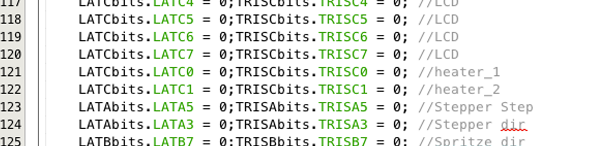
//config outputs
LATCbits.LATC2 = 0;TRISCbits.TRISC2 = 0; //LCD
LATCbits.LATC3 = 0;TRISCbits.TRISC3 = 0; //LCD
LATCbits.LATC4 = 0;TRISCbits.TRISC4 = 0; //LCD
LATCbits.LATC5 = 0;TRISCbits.TRISC5 = 0; //LCD
LATCbits.LATC6 = 0;TRISCbits.TRISC6 = 0; //LCD
LATCbits.LATC7 = 0;TRISCbits.TRISC7 = 0; //LCD
LATCbits.LATC0 = 0;TRISCbits.TRISC0 = 0; //heater_1
LATCbits.LATC1 = 0;TRISCbits.TRISC1 = 0; //heater_2
LATAbits.LATA5 = 0;TRISAbits.TRISA5 = 0; //Stepper Step
LATAbits.LATA3 = 0;TRISAbits.TRISA3 = 0; //Stepper dir
LATBbits.LATB7 = 0;TRISBbits.TRISB7 = 0; //Spritze dir
LATBbits.LATB6 = 0;TRISBbits.TRISB6 = 0; //Spritze dir
//config inputs
LATBbits.LATB5 = 0;TRISBbits.TRISB5 = 1; //button up
LATBbits.LATB4 = 0;TRISBbits.TRISB4 = 1; //button down
LATBbits.LATB3 = 0;TRISBbits.TRISB3 = 1; //button left
LATBbits.LATB2 = 0;TRISBbits.TRISB2 = 1; //button right
LATBbits.LATB1 = 0;TRISBbits.TRISB1 = 1; //external_dir
LATBbits.LATB0 = 0;TRISBbits.TRISB0 = 1; //external step
//Timer1 for step-driver
T1CON = 0b00000011; //Config Timer1
IPR1bits.TMR1IP = 1; //Setting Timer1 to high-prio
PIE1bits.TMR1IE = 0; //Disable Timer1 Interrupt
PIR1bits.TMR1IF = 0; //rest TMR1-Interrupt flag
RCONbits.IPEN = 1; //enable High/Low-Prio
ei(); // master switch to enable interrupt
INTCONbits.GIE_GIEH = 0; //disable all High-Prio-Interrupts
INTCONbits.PEIE_GIEL = 1; //enable all Low-Prio-Interrupts
After this the LCD is fired with data for the first time. Not a big deal with the XC8-included lib:
  // LCD Init

    Lcd_Init();

    sprintf(s, "This is ");

    Lcd_Set_Cursor(1,1);

    Lcd_Write_String(s);

    sprintf(s, "PastExtruder!");

    Lcd_Set_Cursor(2,1);

    Lcd_Write_String(s);
As you can see, first a string is filled with sprintf, then this string is send to the display after setup which line should be used.
Then the program loops in a while-loop. Every time it loops the buttons left and right are read in to
setup a variable called "menue". With this variable is choosed which menu-display is active.
No matter in which menu-mode you are, the timer-interrupt lets the pic check the temperature of the heaters every 5ms...
The code is mainly commentaded and easy to read i think, so here it is:
    if (menue == 0)  //show the actual temperatures and the motor-current

    {

        INTCONbits.GIE_GIEH = 1; //enable all High-Prio-Interrupts

        if (temp_soll_update == 1){

            saved_temp_1 = (temp_1_soll_display / 0.265) + 1970;

            saved_temp_2 = (temp_2_soll_display / 0.265) + 1970;

            temp_1_soll = saved_temp_1;

            temp_2_soll = saved_temp_2;


            temp_soll_update = 0;

        }

        saved_temp_1 = temp_1_ist;

        saved_temp_2 = temp_2_ist;

        temp_1_ist_display = (saved_temp_1 - 1970) * 0.265;

        temp_2_ist_display = (saved_temp_2 - 1970) * 0.265;

        sprintf(s, " T1    T2    MC ");

        Lcd_Set_Cursor(1,1);

        Lcd_Write_String(s);

        sprintf(s, "%2.1f  %2.1f   %i        ", temp_1_ist_display, temp_2_ist_display, motor_current_ist);

        Lcd_Set_Cursor(2,1);

        Lcd_Write_String(s);

        sleep(250);

    }


    if (menue == 1)  //setup the temperature of heater 1

    {

        INTCONbits.GIE_GIEH = 0; //disable all High-Prio-Interrupts

        sprintf(s, "Temp 1:         ");

        Lcd_Set_Cursor(1,1);

        Lcd_Write_String(s);

        sprintf(s, "%i deg. C             ", temp_1_soll_display);

        Lcd_Set_Cursor(2,1);

        Lcd_Write_String(s);

        if (btn_up == 0) {

            temp_1_soll_display++;

            temp_soll_update = 1;


            sleep (100);

        }

        if (btn_down == 0) {

            temp_1_soll_display--;

            temp_soll_update = 1;

            sleep (100);

        }

    }


    if (menue == 2)  //setup the temperature of heater 2

    {

    INTCONbits.GIE_GIEH = 0; //disable all High-Prio-Interrupts

    sprintf(s, "Temp 2:         ");

    Lcd_Set_Cursor(1,1);

    Lcd_Write_String(s);

    sprintf(s, "%i deg. C             ", temp_2_soll_display);

    Lcd_Set_Cursor(2,1);

    Lcd_Write_String(s);

    if (btn_up == 0) {

        temp_2_soll_display++;

        temp_soll_update = 1;


        sleep (100);

    }

    if (btn_down == 0) {

        temp_2_soll_display--;

        temp_soll_update = 1;

        sleep (100);

        }

    }


    if (menue == 3)   //setup the motor-current

    {

        INTCONbits.GIE_GIEH = 0; //disable all High-Prio-Interrupts

        sprintf(s, "Motor Current:  ");

        Lcd_Set_Cursor(1,1);

        Lcd_Write_String(s);

        sprintf(s, "%i  mA            ", motor_current_soll);

        Lcd_Set_Cursor(2,1);

        Lcd_Write_String(s);

        if (btn_up == 0) {

            motor_current_soll++;

            sleep (100);

        }

        if (btn_down == 0) {

            motor_current_soll--;


            sleep (100);

        }

    }


    if (menue == 4)  //drive the motors by hand to fill-in material

    {

        INTCONbits.GIE_GIEH = 1; //enable all High-Prio-Interrupts

        sprintf(s, "Manual drive   ");

        Lcd_Set_Cursor(1,1);

        Lcd_Write_String(s);

        sprintf(s, "                ");

        Lcd_Set_Cursor(2,1);

        Lcd_Write_String(s);

        if (btn_up == 0) {

            spritze_dir = 1;

            stepper_dir = 1;

            spritze_pwm = 1;

            stepper_manual = 1;

            while (!btn_up){

                if (motor_current_ist >= motor_current_soll) spritze_pwm = 0;

                else spritze_pwm = 1;

            }

        }

        if (btn_down == 0) {

            spritze_dir = 0;

            stepper_dir = 0;

            spritze_pwm = 1;

            stepper_manual = 1;

            while (!btn_down){

                if (motor_current_ist >= motor_current_soll) spritze_pwm = 0;

                else spritze_pwm = 1;

            }

        }

        stepper_manual = 0;

        spritze_pwm = 0;

    }


    if (!btn_left) {

        menue--;

        if (menue < 0) menue = 4;

        while (!btn_left);

        sleep (100);

        }


    if (!btn_right) {

        menue++;

        if (menue >= 5) menue = 0;

        while (!btn_right);

        sleep (100);

        }
Finaly there is the code for the external-interrupt. This Pin is connected to the step-signal of my smoothie-board and reads in
the extruder-commands writen in the g-code:
  if (INTCONbits.INT0IF == 1)

     {

         stepper_dir = external_dir;

         stepper_step = external_step;

         if (INTCON2bits.INTEDG0 == 0) INTCON2bits.INTEDG0 = 1;

         else INTCON2bits.INTEDG0 = 0;


         INTCONbits.INT0IF = 0;

     }
Thats all, wasn´t too much, don´t you think ;)
And here is the whole mplab-project-folder for you to download:
ZIP-File