Output devices

This week was about output devices, such as RGB Leds, LED arrays (Charlieplexing), LCD screens, motors and sound speakers, but also electrical safety. See also the link to the global lecture.
The assignment: Add an output device to a microcontroller board and program it to do something.
In the previous week, I relatively spend a lot of time soldering and making my own boards with the Modela milling machine. Although some attempts had been succesful, my Fabkit still needed more love and care for it to be a fruitful base. So after Emma's informative local lecture, that is what I started with.
Tip: Do not solder (or use small/big machinary) right after surgery...
LED it be-ep
Without going into the details, this initial approach was not the best idea. I needed to give myself some recovery time, but also really wanted to progress. So thinking of creative alternatives I could do at home, I thought it would also be interesting to experiment with making my own (copper) paper circuits (with sticker LEDs) and the Touch board for sound output. As I have a lot of such interesting material around, it would be a waste not to try it! Also, sound output and LED action was what I wanted to implement for my final project, so all things considered, I think this was the best direction to go.
Using conductive paint from Bare conductive, I had painted simple circuits before. As in my experience this takes some time to dry and can get a bit messy, I decided to trial sticky copper tape. In addition, I used 3V batteries and cool stuff from Chibitronics, particularly LED stickers. The complex circuit with LED effects I started off with did not work, so I made a simple LED circuit which worked with firmer sticking. I used semi-transparant paper (and could also use transparent fabric) which hides the circuit in an easy and elegant way. For making and programming more complex boards, adding the microcontroller (ATtiny85) sticker is an interesting option. All together, I found this a nice and accessible approach for board making and LED output that I would like to explore further in future .
Charlieplexing
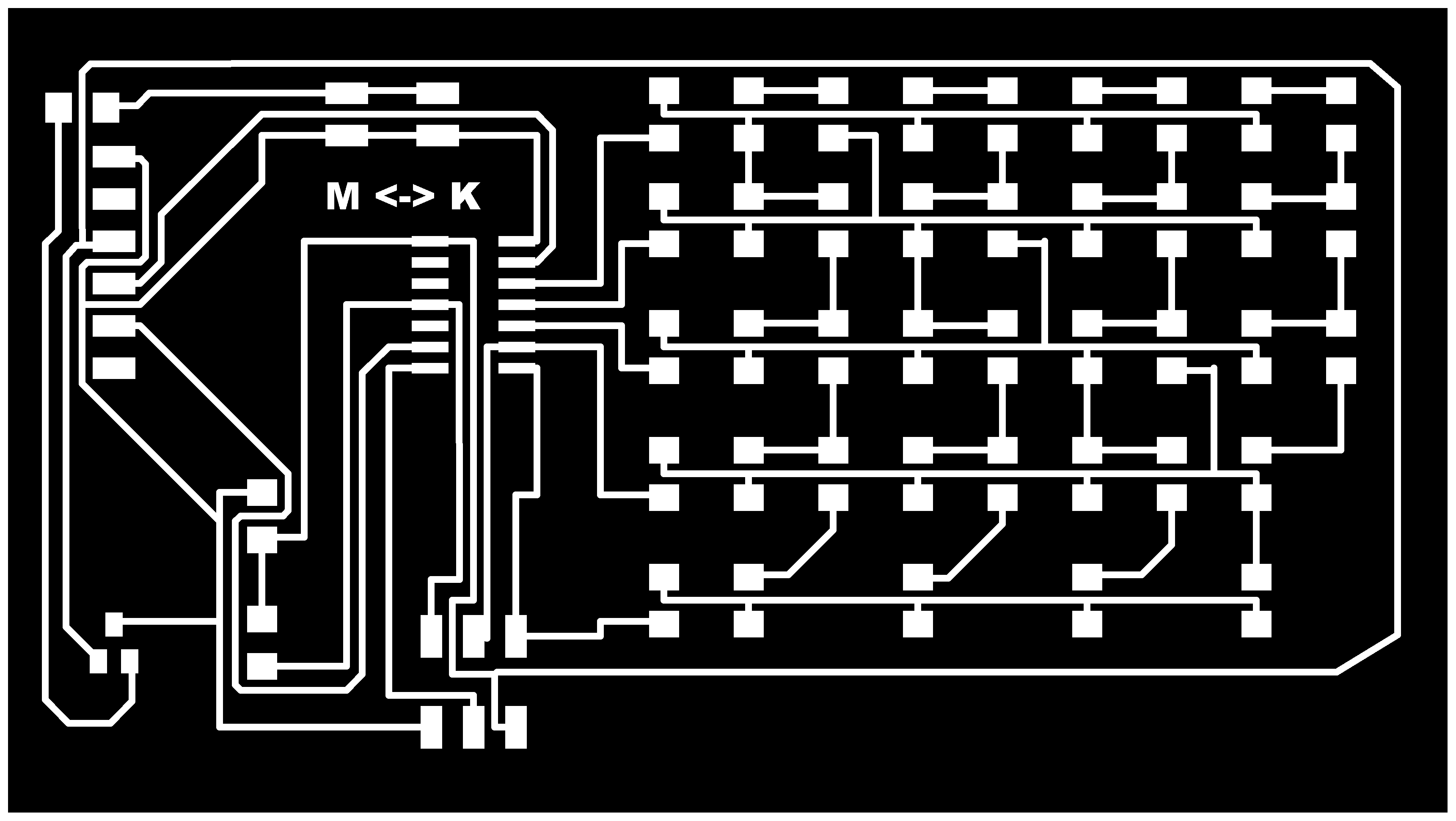
Another interesting approach I found for LED array display is charlieplexing, a technique for driving a multiplexed display in which relatively few I/O pins on a microcontroller are used to drive an array of LEDs. Charlieplexing is basically a method to control n * (n-1) LEDs using only n I/O ports of a microcontroller. Thus for example with 5 I/O ports, you can control 5 x 4 = 20 LEDs independently. See also Instructables and Makezine. If one I/O port is set to L, then the other ports can be set to either H or Z. For every port set to H, exactly one LED will be activated.
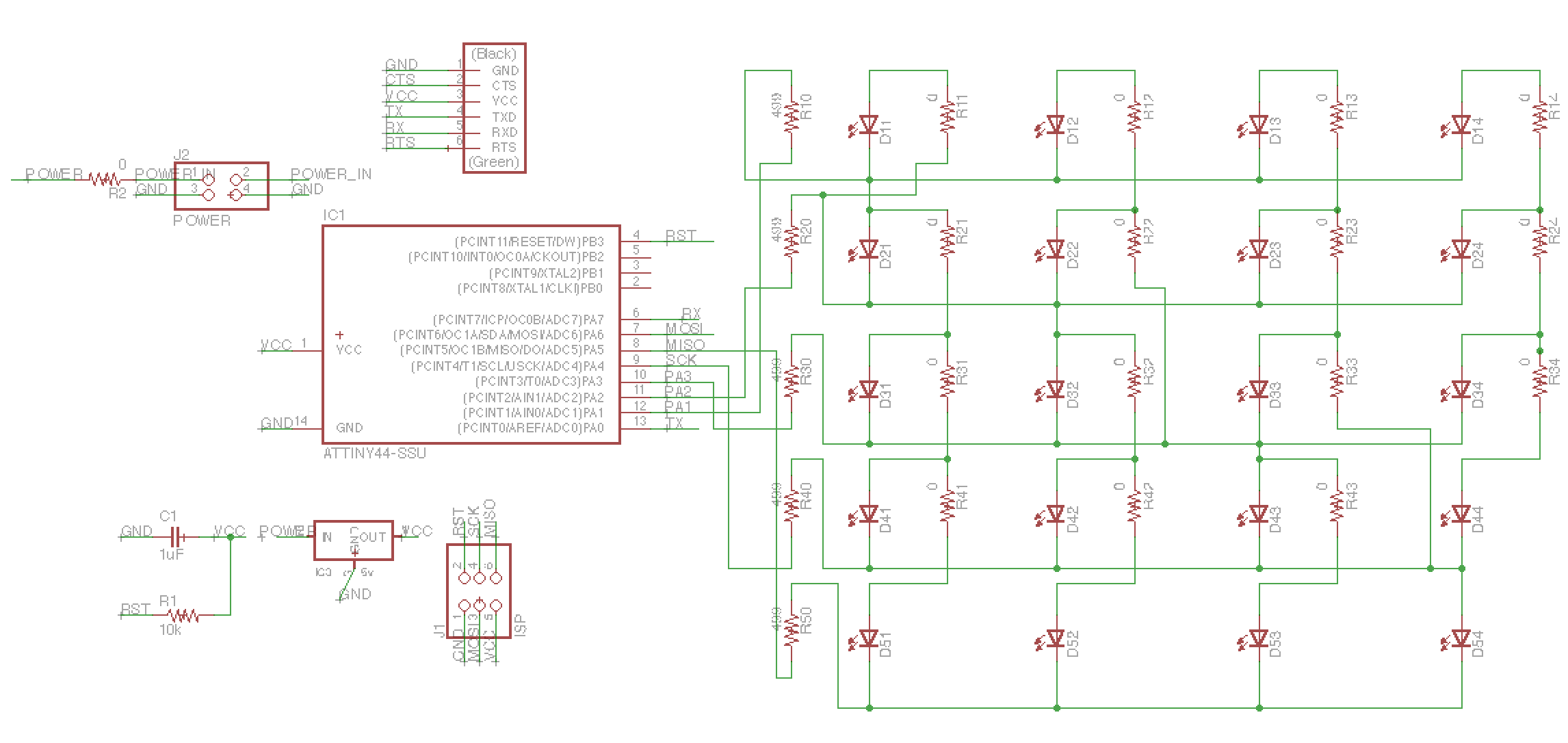
Using Eagle and the Modela I designed a board for Charlieplexing. This was based on Neil's board, but definitely needed some tweaking to comply with the design rules. The first board I tried to mill got side tracked just at the very right end, probably because the lines of the cut file were not the proper width (even though I had followed the fab tutorial: 20 pixels should be 1mm for the Modela). During the second one, the milling machine just stopped right in the middle, so it was better to delete the job (from the Modela and using the terminal). The third one came out ok-ish after some sanding and manual cutting. It was frustrating that it did not come out perfect, as I had checked all the settings, carefully fastened and selected the right end mill, made sure the tape was put on the right way (no crossing lines) to ensure a flat base, etc. The issue was probably that the copper plate itself was a bit bend (so I should have even more carefully placed the tape to correct this) and that the default settings from the Fab modules had not been automatically set to default, so one should always remember to check these as well.
All in all, it is a useful board design for LED action in my final project. Also, I added a FTDI connection to the design.
 Mind the datasheet
When designing circuit boards, such as for Charlieplexing, it is useful to read the datasheet(s) of the electronic components, such as LEDs and micro controllers. It is particularly useful for the power requirements (helpful for not damaging the component, calculating which resistors are needed, etc) and the pin outs (useful for rightly connecting and adressing the component).
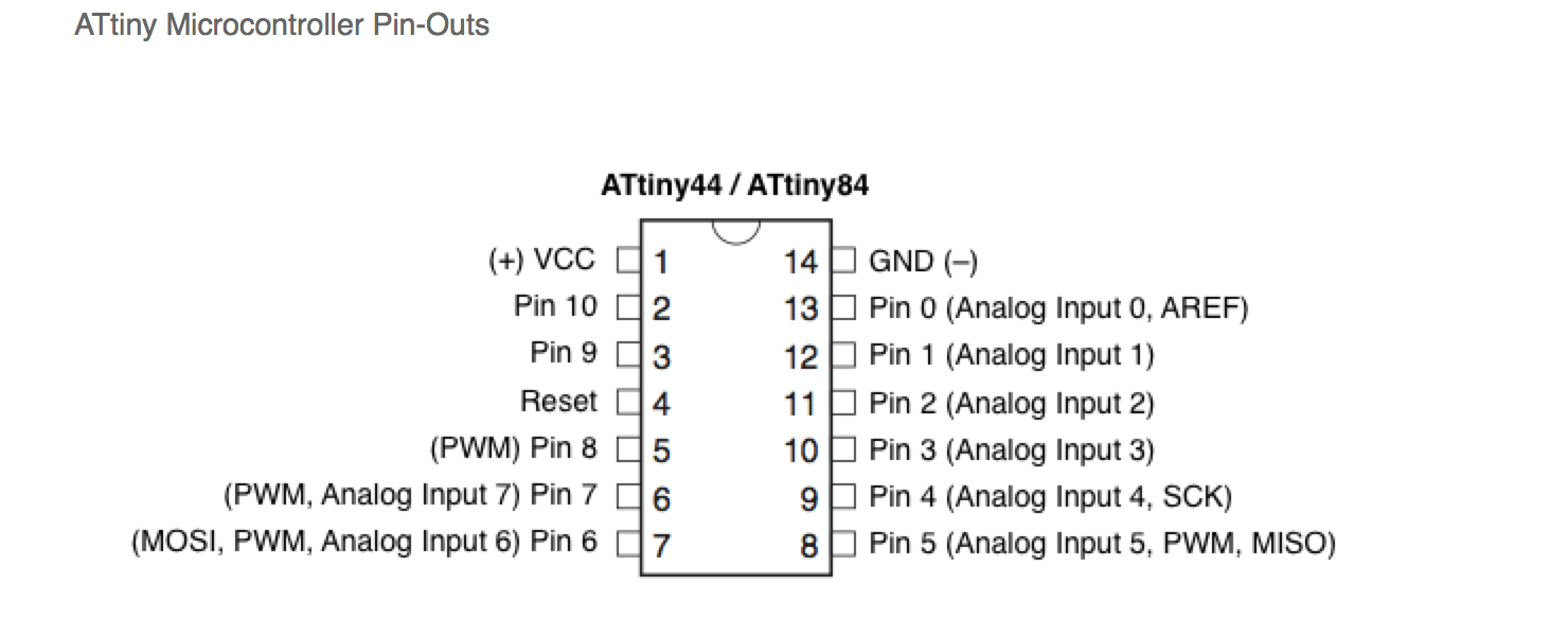 I found that LEDs of different colour can take different current (e.g. green and red more than blue ones). Furthermore, the ATtiny44 datasheet (as discussed during the Embedded programming week) shows that the operating voltage is 2.7-5.5V, which means that if you connect VCC to more than 5.5V, you burn the ATtiny. Consequently, to generate a fixed output voltage I used a 5V regulator.
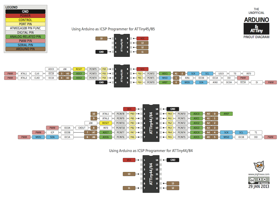
Also the limited i/o pinouts on the ATtiny44 are important to consider. Charlieplexing is a useful technique for driving LEDs with relatively few i/o pins (so that you can use limited hardware, and do not always need to use more powerful Arduino/Fabkit kind of microcontrollers with more pins). Furthermore, Arduino defines its own pin numbering for microcontrollers which is different from Atmel's numbering. I found this pin out schematic very useful for understanding and defining the pins, particularly when coding in the Arduino IDE.
Hacking sound
For my final project, I wanted to add different sound fragments to specific objects. According to the Dutch saying "Van het kastje naar de muur" (from cabinet to the wall), my idea is that the cabinet (het kastje) says "ga naar de muur" (go to the wall) and the wall (de muur) says "ga naar het kastje" (go to the cabinet). Realizing this gets a bit lost in translation, I also wanted to implement the sound fragment "Please, don't stand so close to me" from The Police's song as I thought it would be nice to combine this with the distance sensor (used in the input devices week). Now for adding such sound, a number of things are needed in terms of electronic board design: recording (via a microphone), storing (on or off the board) and playing sound (through a speaker).
The first thing I came up with was to use stand-alone voice recorder modules which are often used in message greeting cards. I found these to be a cheap (±E4,-) and accessible way to record and add voice output. A nice idea for everyone that wants to hack and add sound to objects. However, the sound quality of the ones I tested was not great; just enough for adding a simple (noisy) voice fragment, but not for MP3 quality song output. For realizing the latter, I configured the Touch Board and used its functionality for capacitive touch and MP3 Player. I got a micro-SD card reader (from the HEMA) to record MP3's from my computer on a micro SD card and then to transmit, store and play it from the board (see also the Bare coductive page). I lost my touch board while travelling to the States (security?), but hopefully it will somehow be returned to me again as I would like to demonstrate it here...
Creating mp3 sound output
For creating the voice mp3's I used Audacity (a simple sound production tool) and its different effects (such as pitch and speed) and media.io, an online audio converter. I re-bought The Police song from iTunes (there are different versions, but I prefer The Police greatest hits version) and used this tool for cutting mp3s. Result: Depending on the touch input (associated with the different sound fragments) it plays the different sound output. Sounds good!
Files
- MP3 Sound fragment Go to the wall (ga naar de muur)
- Mp3 Sound fragment Go to the cabinet (ga naar het kastje)
- Charlieplexing (Eagle files: .brd & .sch | Cut .png file & Traces .png file)


")
")


")
soldering the board was able to initialize")
