Networking and communications

Recitation: The state of the Fablab network
This week I spend most of my time networking and communicating at CHI2016 (world's most renowned conference in the area of Human Computer Interaction), in San Jose to present this work:
Assignment: Design and build a wired and/or wireless network connecting at least two micro-processors.
Learning outcomes:
- Demonstrate workflows used in network design and construction
- Implement and interpret networking protocols
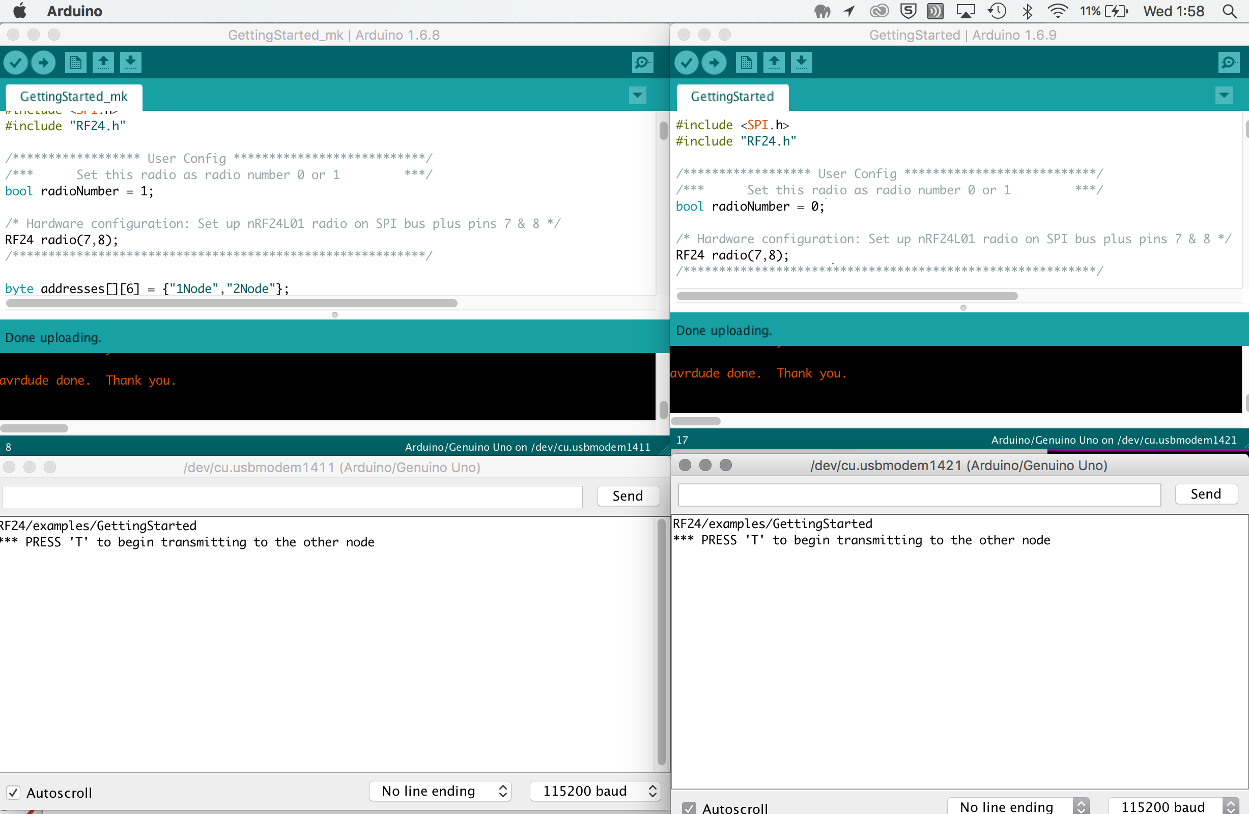
For the assignment and potentially making my final project run stand alone from a computer, I decided to first explore with the nRF24L01(+) 2.4GHz Wireless Transceiver. I mostly followed this tutorial (warning: lots of Comic sans), using two Arduino Unos (which could be replaced by Fabkits), male/female jumper wires, two usb- cables and the two radio modules. I carefully followed the details of the Pinout and connections to Arduino (Using the Arduino pin for TMRh20 RF24 Library colomn in the tutorial table). For the library, the easiest thing I found was to go to Sketch > Include libary - and select the desired library from there. After I got it running for 1 node, I added the other Arduino and changed the code (from 1 to zero). When pressing T, the (rx) lights of the Arduino's were reassuringly flashing. For obtaining two serial monitors in Arduino, I downloaded an extra newer version of Arduino (1.6.9), so to have two instances running. However even after that was working, and also having selected the right ports and baud rate, I did not get the final message of receiving. Maybe I mistook the top view?
 Update
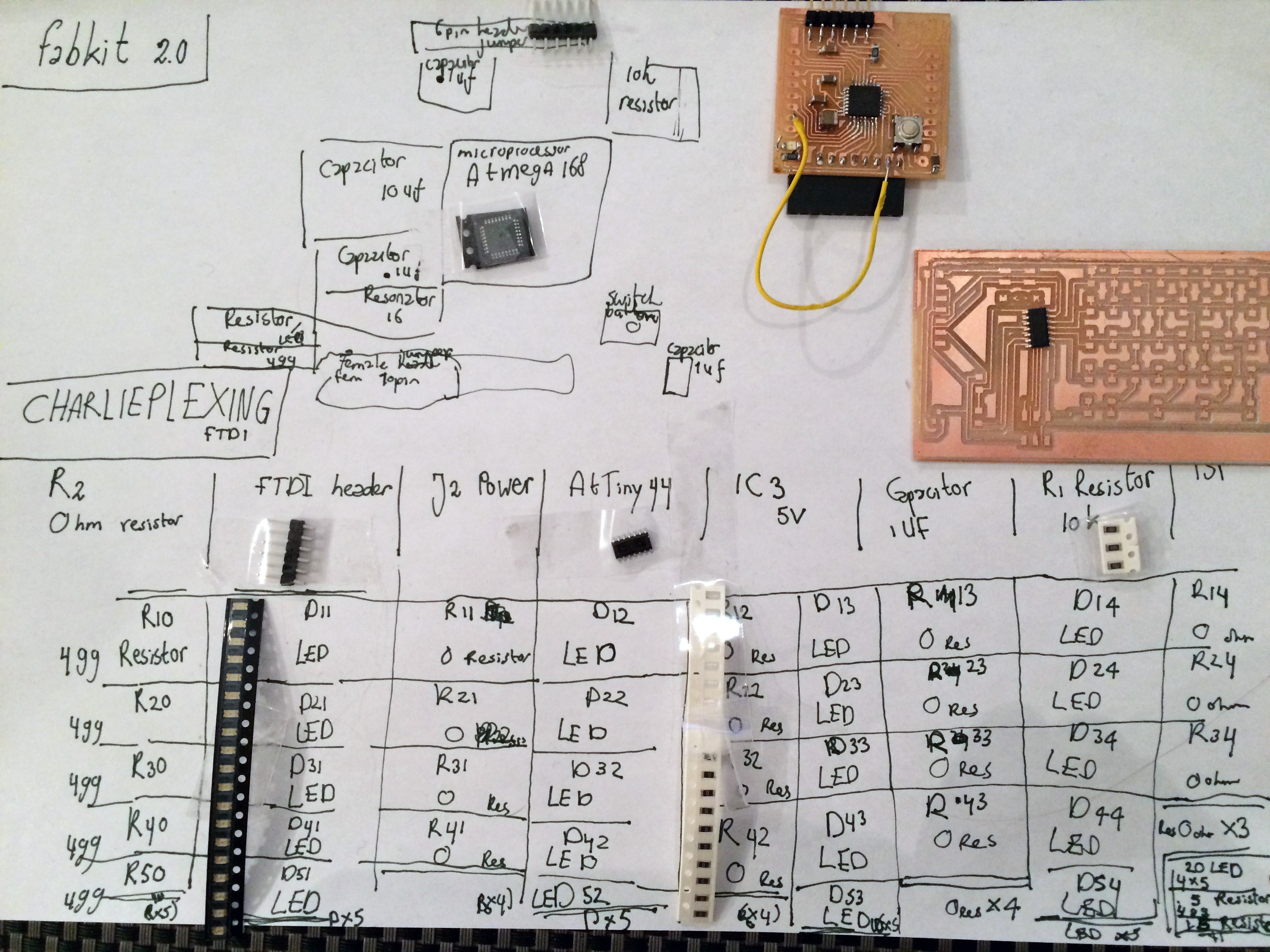
Without an abandunce of working fabkits around, I continued on the neverending journey of getting my own fabkit to work, so to also test communication with this. After extensive testing with the multimeter, the microcontroller still burnt (because the wire that replaced a lacking trace had moved and caused a short...). On the positive side, in the process, I learned how to use the reflow machine at my university for resoldering the microcontroller (and about getting better soldering results with flux -though because of allergens it was better not to explore further). This particularly worked well for soldering the ATtiny44 microcontroller which has more space between the pins. What also worked well for transportation between labs was writing down and sticking all the needed components on a sheet.
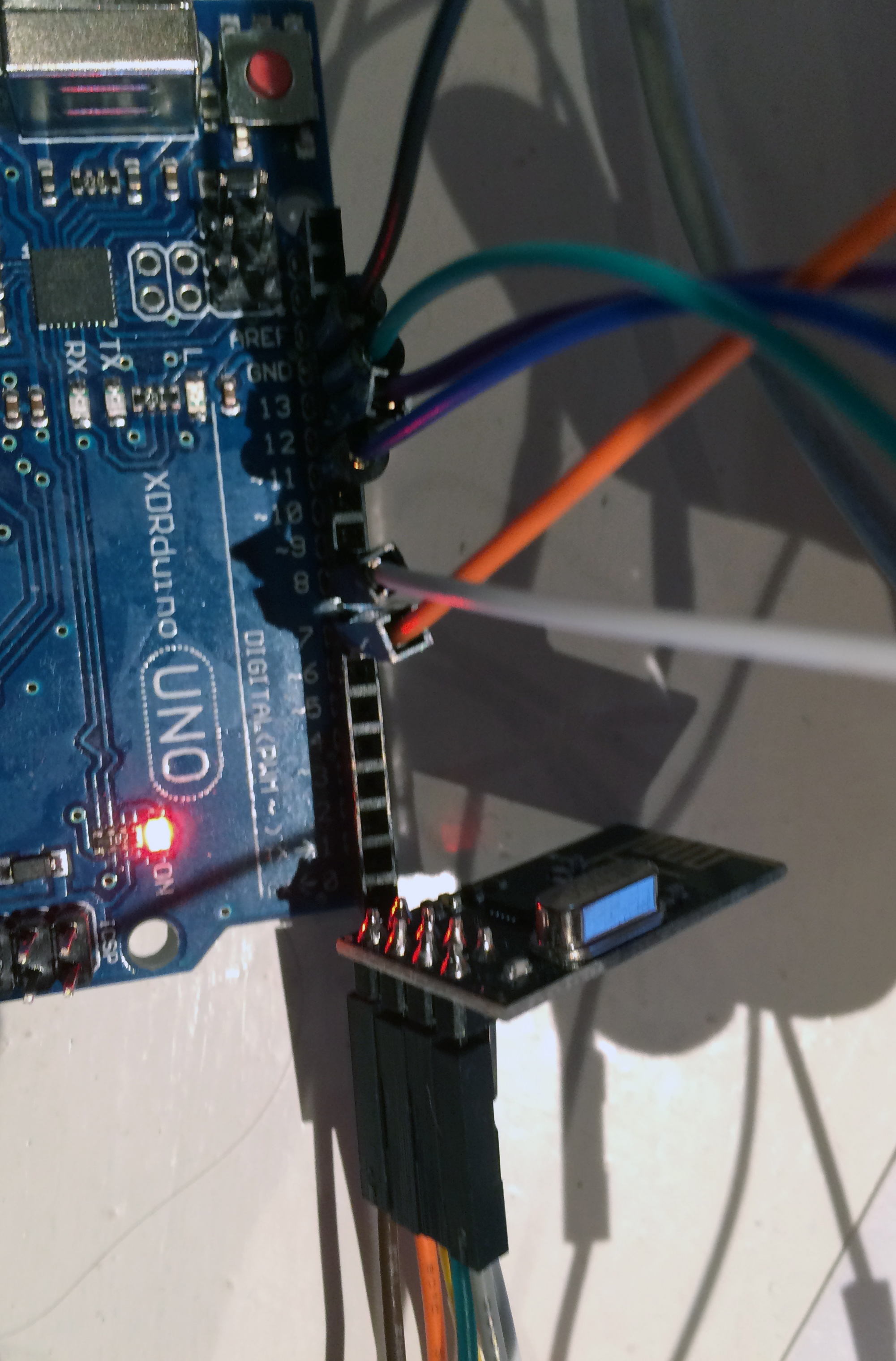
 Also, I got the RF communication to work. As stated in the tutorial, often power issues can be to blame. However, in this case, I found that there was an error in the tutorial; after inverting the top view and rewiring, the connection worked indeed!
Finally: more communication
For my final project, I also worked on serial communication between (1) my ATtiny44 board for Charlieplex animation, and (2) Touch board (with Atmel's ATMega32U4 microprocessor) for sound output with ultrasonic distance sensor. The reason for doing this was that I wanted LEDs reacting to the sensed distance, as well react in parallel with sound.
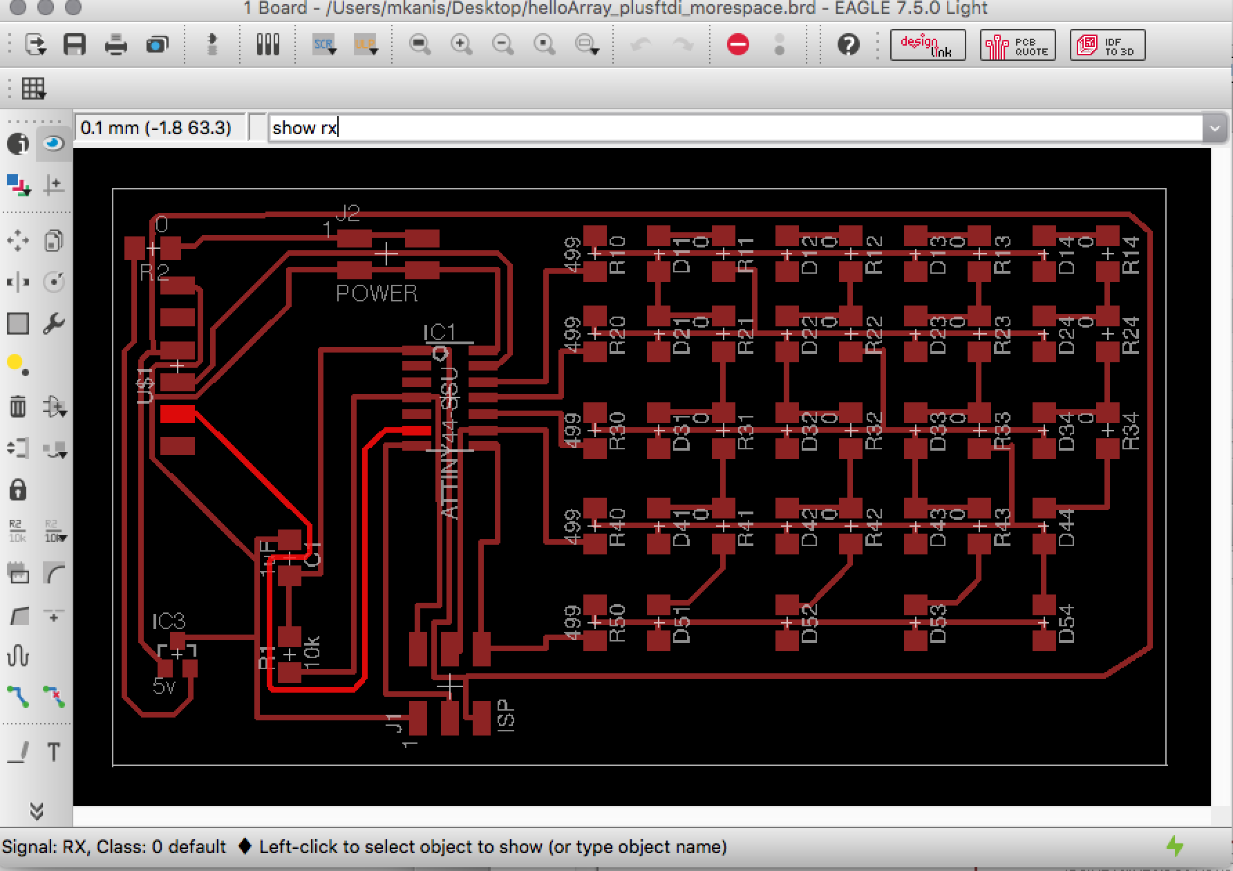
To accomplish this, I used Arduino's serial library (#include <SoftwareSerial.h>) and the TX and RX pinouts of the boards (ATtiny44 board: #define rx 7 / #define tx 0 - Touch board: #define rx 0 | #define tx 1). More precisely, what was needed was the connection between the TX pinout of the Touch board for byte transmission (the TX/RX pin outs on the Touch board turned out to correspond the same as for the Arduino Uno), with the RX of the Charlieplex board on the receiving end. For rightly wiring the connections of my Charlieplex LED board, I used the Show command in Eagle to identify VCC, GND and RX.
 The code could be seen as my own communication protocol and works like this (on 'master' Touchboard):
} if (distance <= 6){
MP3player.playTrack(muur);
serial.write(1);
}
else if (distance <= 12){
MP3player.playTrack(kastje);
serial.write(2);
}
else {
// does not play audio and should then show neutral LED
serial.write(3);
}
delay(500);
}
The code on the 'slave' Charlieplex board then checks if the serial port is available (while (mySerial.available()) {) and then plays a different animation sequence depending on the serial communicated case 1, 2 or 3; the distance scenario sensed via the other board (as simply shown in the video).
Tips
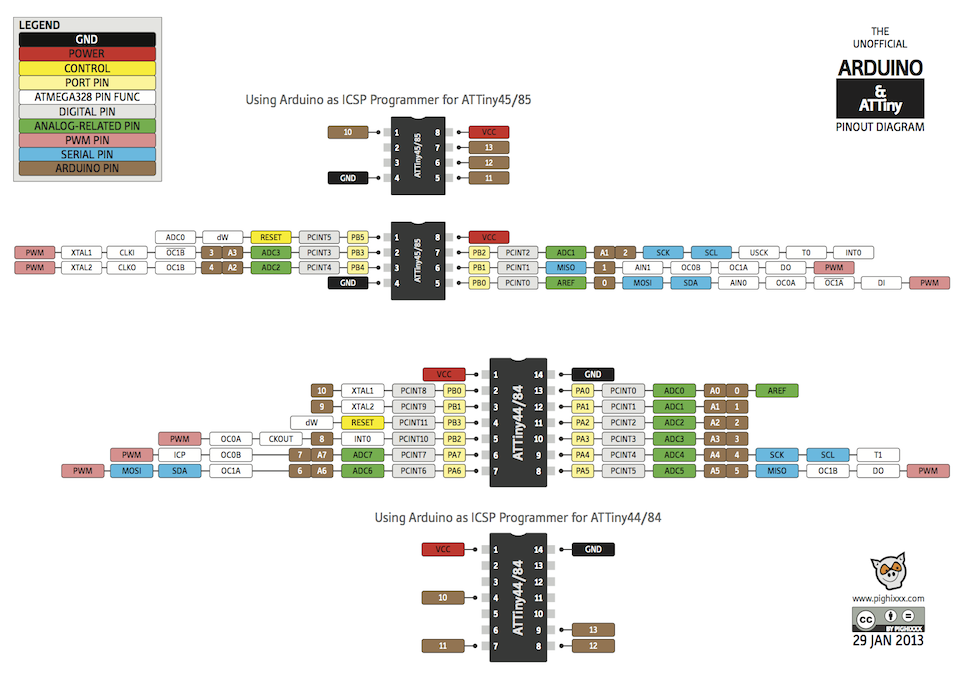
- ATtiny/ Arduino pinout diagram (for identifying the Arduino IDE corresponding pin outs)
- Make sure to declare the serial port correctly (SoftwareSerial serial(rx,tx);)
- The baudrate (e.g. serial.begin (9600);) and timing (e.g. delay(500)) that is written in the code of both boards should be alike (or else the boards will not function synchronously)
I have
- Described the design of the networking process using words/images and screenshots.
- Explained the programming processes used
- Outlined problems and how I fixed these
- Included original design files and code
Files
- Code for nRF24L01 communication between boards (.ino)
- Code tip: For board number 1- bool radionumber = 0 / For board number 2: bool radionumber = 1
- Code for serial communication between my ATtiny44 board for charlieplex animation (simple LED animation code | fancy LED animation code) and touch board for sound output with ultrasonic distance sensor (.ino)


