Computer-controlled machining

Assignment: Make something big (on a CNC machine)
Bigger, Better
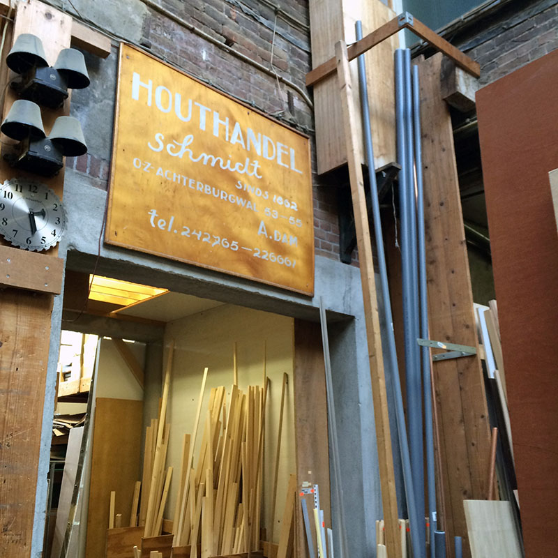
This week was about big machinary, namely the Shopbot. It is a powerful milling machine that can get you killed (if not careful), but can also make big nice things, such as boats and furniture. Neil Gershenfeld told about the do's and don'ts of Computer-controlled machining and Mickael gave us the necassary practical and safety training on site. We got our wood (2500 x 1220 x 9 mm) from Houthandel Schmidt in Amsterdam, a nice shop (more than 150 years old) just around the corner from the Waag's Fablab Amsterdam.
 The milling machine can do vector cutting and 3D engraving with various materials such as wood and styrofoam. The advantages of CNC milling are precise cut lines on large scale (without the typical burned colour look you can get with laser cutting).
Meten = Weten (meaSURE!)
With the Shopbot, it is important to always know for sure (measure or ask if you do not know). Choose the right milling bits and settings depending on the job and material, as it is preferable to not set fire... (e.g. ignited by little hot pieces of wood flying around). Thus setting up typically takes much longer than with a laser cutter, and should not be done in a haste or blurry state of mind.
The most important thing are the safety procedures and steps (see picture). Another important aspect of the Shopbot is that the inner corners of the vector files should be prepared with 'dog bones' to have a cleaner corner. Also, lines should be joint together and not be double (as I experienced myself...). To join the lines, you can select all lines in PartWorks software and Edit - Join lines to correct this. You can prepare the design in vector-oriented programs such as Adobe Illustrator, Inkscape or Fusion 360 and export it as .AI .DXF or .PDF file. After (at the Waag), we use PartWorks 2 (similar to VCarve) to prepare and export the right tool paths (such as drilling, milling or pocketing) and settings (such as end mill selection and material thickness), and Shopbot software to run the job.
Stronger, Faster
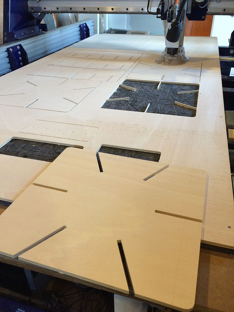
First thing I did when milling, was fixating the wood to the sacrificial layer (with normal hand drilling machine). I put in quite a lot of them to stop the wood from 'dancing'.
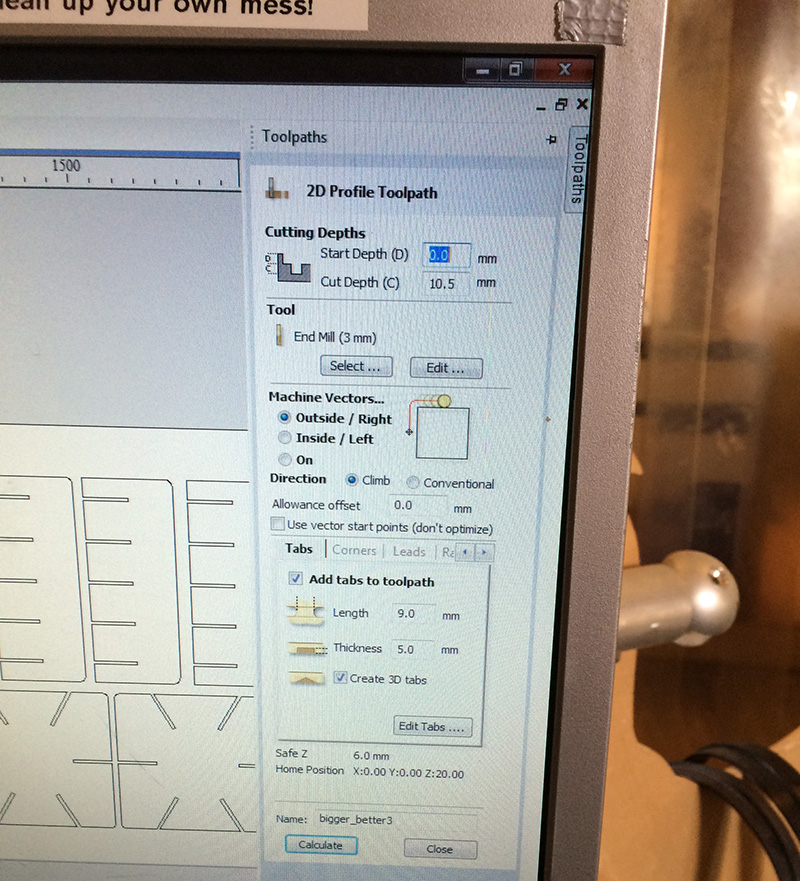
Then, I created a toolpath (using PartWorks), which holds different settings that Shopbot needs to perform its job. When preparing the files, it is important to add 'tabs' to the design to ensure additional proper fixation while milling. The settings for the tabs I added were not default (as shown in picture), but were strong enough to hold it, because the big pieces were heavy enough.
 Different bits and settings
When using the Shopbot I was really grateful for the help I got from my fellow Fab stars; It is very ensuring to go through the process together when faced with all the Shopbot parameters and aspects to think of.
One of such aspect is to make sure to select all the pieces in the software. In my case, the indicated time (only 12 min) signalled that I had not selected it all (the job took about an hour machining on the Shopbot).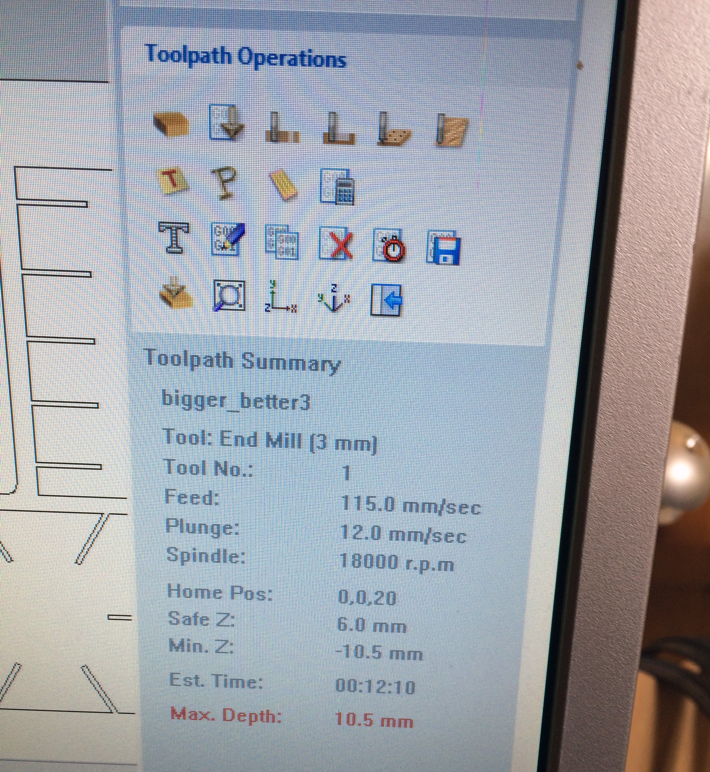 Another aspect to consider are end mills. There are several types of end bits to select from for different types of jobs and materials. Particularly, there are ‘up-cut’ end mills which cut in upward direction and ‘down-cut’ ones which cut downwards. Bits can also have different number of flutes (few is usually enough, but important for calculating proper feed and speed rates). Additionally, the bits come in a variety of end shapes, such as ball (rounded) and flat-end versions. I selected a 3mm up-cutting end mill. For selecting the right bit for your project, see also this link.
 Settings overview
- Tabs: 9 mm length | 5mm thickness | 3D tabs
- Cut depth = 10.5mm (9mm wood width, thus purposefully cutting into sacrificial layer)
- Machine vectors: outside /right
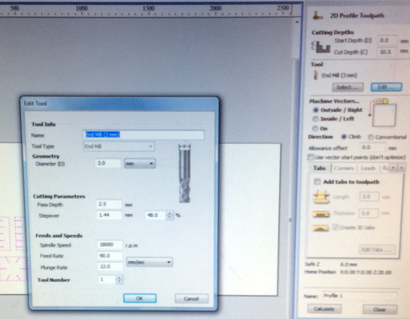
- End mill: 3mm
- diameter: 3mm
- pass depth: 2.5mm
- stepover (11.44 | 48 %): not important for this profiling job
- Feed rate: 115 mm/s (increased during)
- Plunge rate speed (z-axis): 12 mm/s
- Spindle speed: 18000 (set manually)
Additional steps
Once we prepared my file in the PartWorks software (such as adding tabs), there are still some steps to take, namely:
- Check and fix the collet and end mill (used 3mm end mill)
- Make sure it is tight enough (or call someone to do it)
- Make sure the material has been properly fixed with screws all in
- Set the x,y and z axis.
- In the Shopbot software, pressing ‘K’ will display the keyboard enabling you to set the x-,y- and z- axis before starting to cut. Pressing 'move to', will make it go to the specified location
- You can control the x- and y-axis of the Shopbot with the arrow keys (additionally press the CTRL key for a faster journey). The Page up and Page Down keys control the Z- axis. Use the metal plate with alligator clip on the machine to set the Z-axis (make sure it makes an electric circuit by tipping the end mill with the metal plate and looking at the green dot in the Shopbot software).
- If in doubt run an airjob (e.g. I set the z-axis to 60 instead of 0 to perform one)
- Turn on the extraction
- Pull back your hair, wear safety glasses, remove everything and everyone away from the Shopbot,...
- Turn the key to start the spindle (do not leave it in when not milling).
- Set the spindle speed (my manual setting: 18000)
- Check again (if not sure ask), and start milling
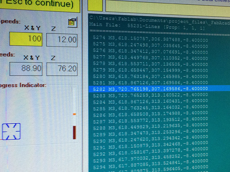 If something goes wrong, just hit the space bar to pause the machine. You can also pause the machine to tweak the settings. For example, when everything was going smoothly (you can hear by the sound the machine makes), I increased the speed (feed rate) from 90, to 100, to 115.
Tips
- Tutorial explaining the Shopbot basics (such as different upward and downward cutting end mills with different flutes for more or less precision)
- When creating a toolpath in the Shopbot software, make sure to select everything that you want to mill...
- Leave enough space for the screws
- When making a complex press fit kit, remember or mark their placement on the sheet, so the different parts that need to be put together will not get mixed up
- In PartWorks, it is not possible to scale by entering exact numbers so make sure to design with proper sizing beforehand (using .DXF the size might change)
- Watch the Shopbot explained in this youtube movie (and there are many more)
 Making something BIG!
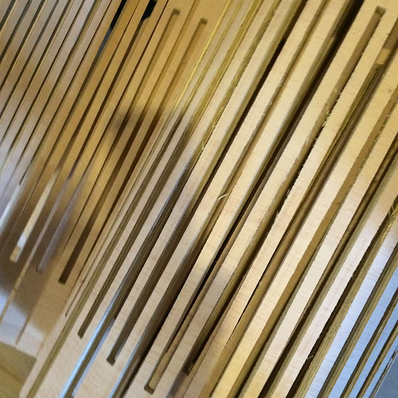
The assignment of this week was to make something BIG. Big like furniture size. The real challenge was to come up with something that would work, without using screws or glue, thus with press-fit and in a total of 3-4 hours (as to equally divide machine time between all). We allocated Friday morning to do some initial testing together (9.0 mm fit was good) and wondered the rest of the day what to make, particularly with the flexures (flexible wood) that Eva had set up based on other's previous work (e.g. such as these). Thinking that it would be nice to use its flexible features for expandable bags, foldable round corners, holders for crates, seating, dynamic storage,... In the process of defining what to make, I set up a Pinterest account with some really nice examples of CNC milling.
 One idea was to use the flexures for a dynamic door opening for a round cornered cabinet (kastje). I also toyed with the idea of adding handles and holes to the flexture for additional fabric to make a bag, and the idea of making a miniature Amsterdam scenary, but those nice ideas were not really 'big' enough.
Parametric design in Fusion 360
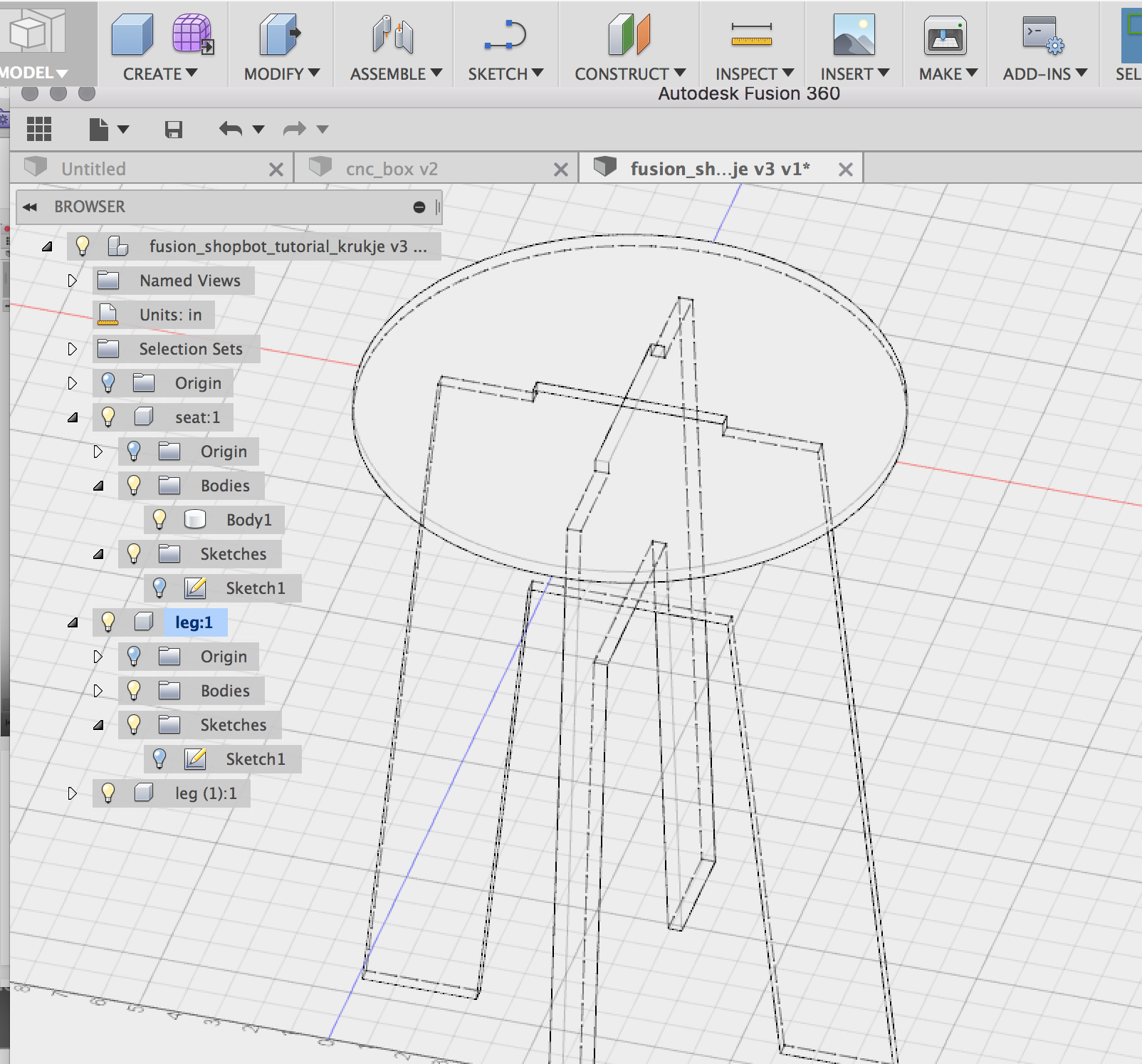
For adding some flexibility into the design file itself, parametric design comes in again. Using a prametric process, enables easy manipulation and editing of the end result using certain parameters or variables (e.g. for material thickness). Using Dynamic symbols in Illustrator duing the week of laser cutting, enabled me to experiment a bit with the parametric process. However, as it was cramping my creative style, I did not use it to full extent. So this week I further explored parametric modelling with Fusion 360, a program that is more suited for such process (as also explained here). For this purpose, I found this really instructive tutorial for flat-pack furniture design for designing a stool while setting various parameters, such as width and height of the legs. It was also a nice way to learn more about Fusion.
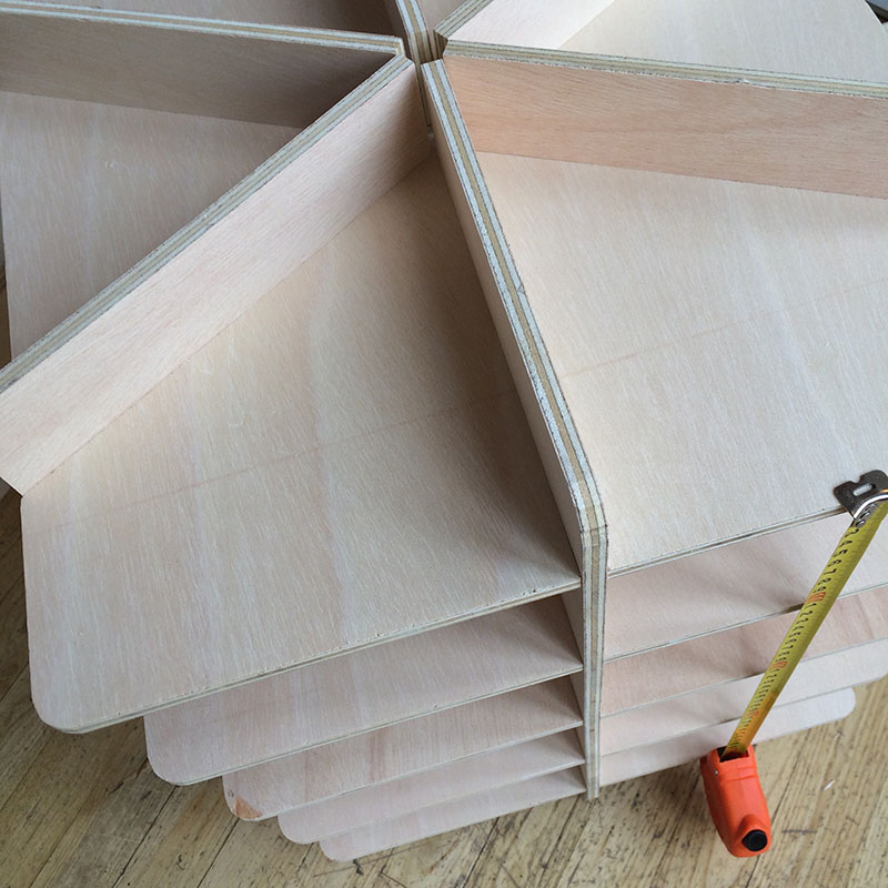
 The big * in the end
During my inspirational search on-line, I saw a lot of chairs and tables, and no(t so many) creative cabinets. I thought it would be nice to have an open one, for putting things like my phone, fab 3D output, and modem/router (yes, a bit nerdy). A cabinet also features in my final project. So in the end, using 123D Make and illustrator, that was what I designed for Shopbot milling (based on my 'mural' design in week 3). The star shape might make it a bit less functional, but adds a creative touch. And still, if you put a pillow on top you can sit on it!
 Files
Files


")


")


")


")
")
")


