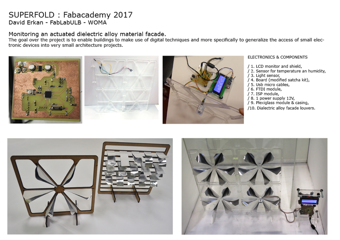
SUPERFOLD FINAL PROJECT
Analogies between nature, geometry and structure.
1. THE IDEA
Origami studies:
1. My project goes about using origami structures as a mean to explore performing architecture.
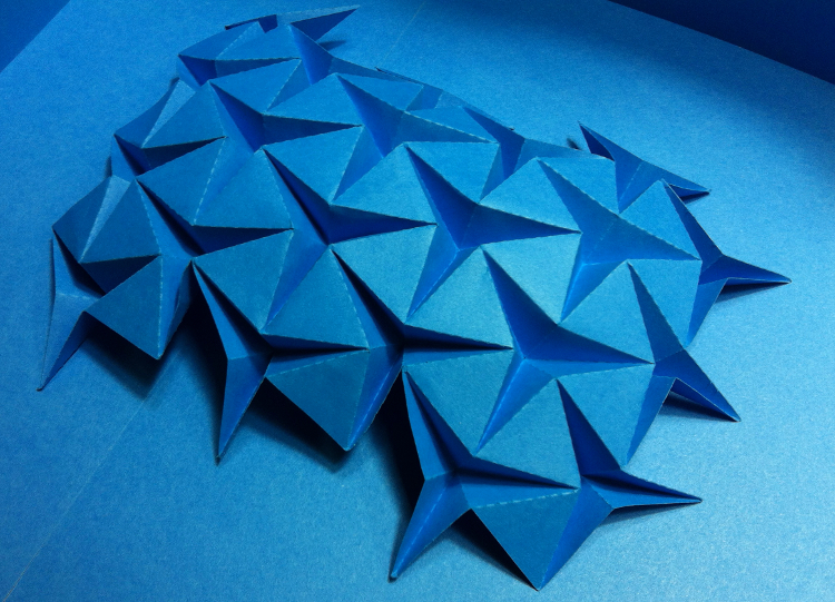
I initially dowloaded different type of origami patterns to test them and find out how easy it is to fold them.
The first origami produced was scored and then folded.
I realized that although scoring the pattern did help the folding,
it also damaged the paper in the process of folding.
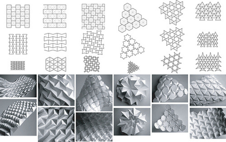
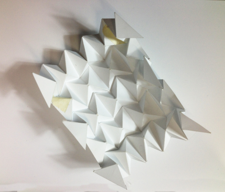

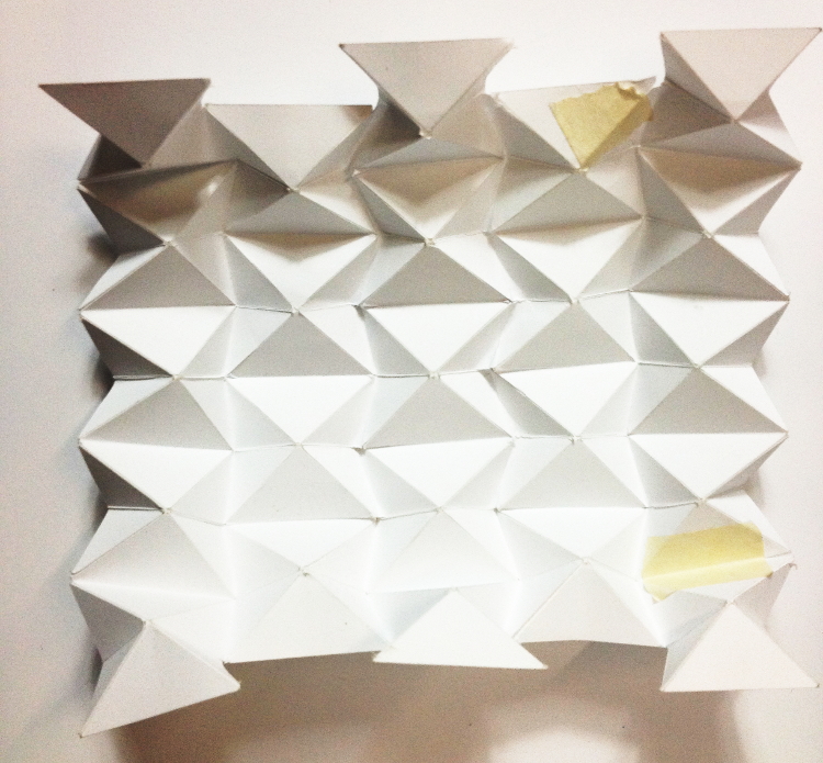
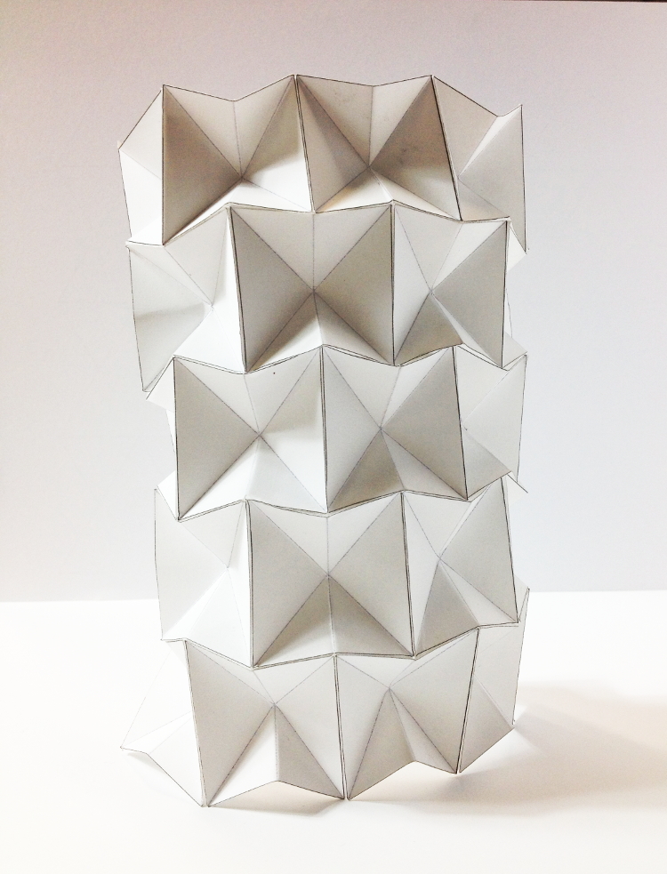
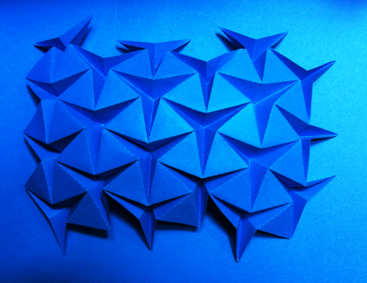
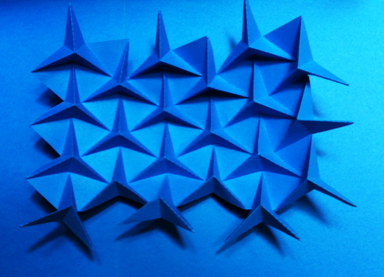
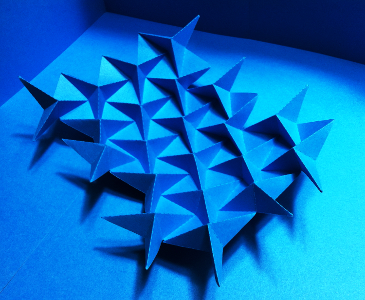
2. Then I decided to laser cut the next pattern. This time, it worked very nicely and the origami produced aquired very good elastic properties, since the paper wasn't damaged in the process. In the following steps, I will keep eploring further the tesseltion patterns and several other patterns in order to famliarise with the different types. Il wil also be looking into building larger version of them and experiment with several sort of material to find out which one will be more suitable for my project.
For my final project, i have decided to work on the principal of an actuated facade with the electric alloy material.
2. THE DESIGN
I started to explore facade skin possibilities trough sketches (Week 1).
Then I made a study about louver behavior trough an origami exercice applied to architecture (Week 2).
I also explored material behavior and worked on more detailed sketches.
2.1. Facade skin studies
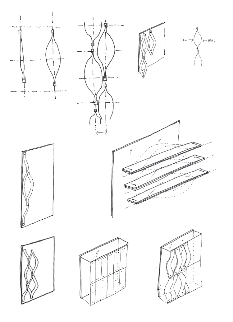
After doing a lot of research about the subject and biomorphic façade systems, I sketched my first ideas.
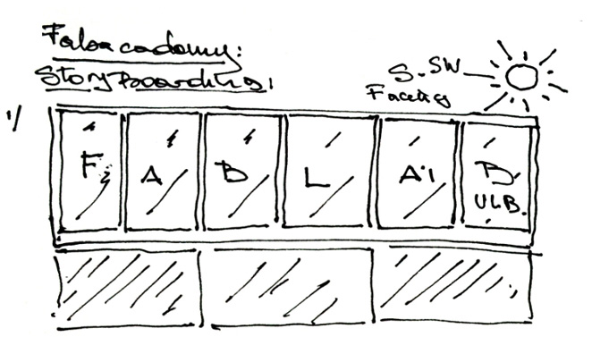
almost completly glazed and poorly insulated. It is therefore exposed to overheating during summer. Besides
the rooms right behind contain the laser cutter and the milling machine; those machines generate already a lot
of heat on their own. So the idea of my project is to work on a sunshading system for that façade. The
underlaying subject of my project is to work on transformable architecture, in this particular case it would
concern a dynamically reactive façade.
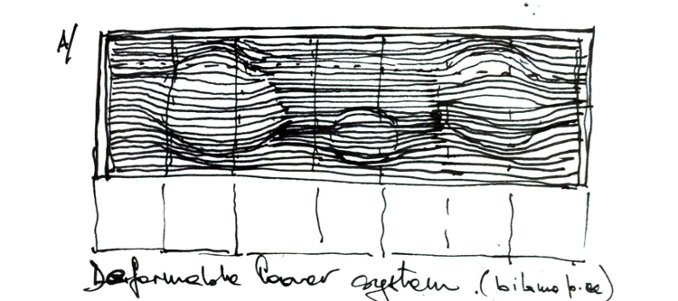
to the mateial behavior.The principle would rely on a parametric louver system that would be able to bulge on demand. Several projects that have tried to deal with the subject inspired me to work on the subject.
The pattern system used for the façade of the Institut du monde arabe building in Paris, from architect Jean Nouvel;
The façade system of the railway info box building in Basel, from architects Herzog & De Meuron; the lotus dome from Studio Rosegaarde; works from Periphérique Architecture, Adeli Capron and Daniel Denis.
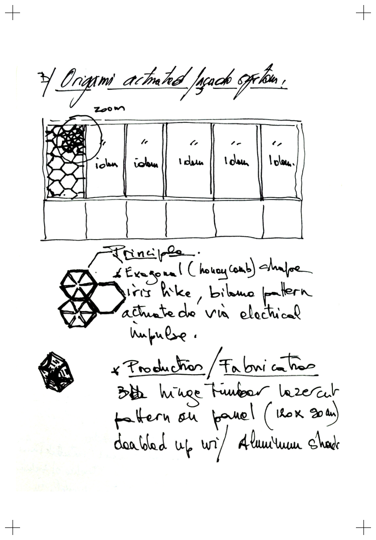
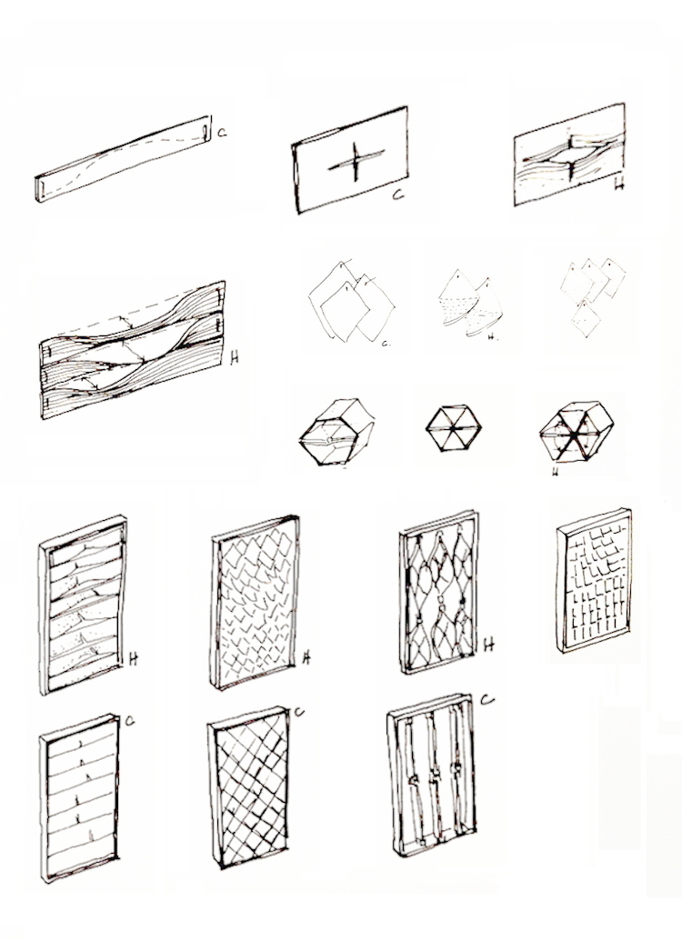
allowing the façade to transform/ bulge with the help of a linear end effector. The exagonal iris honeycomb dielectric alloy shape pattern actuate via electrical inpulse. The prototype can be made with 3D hinge timber lasercut pattern or panel ( approximatively 120cm * 90cm) doubbled up with aluminium sheet.
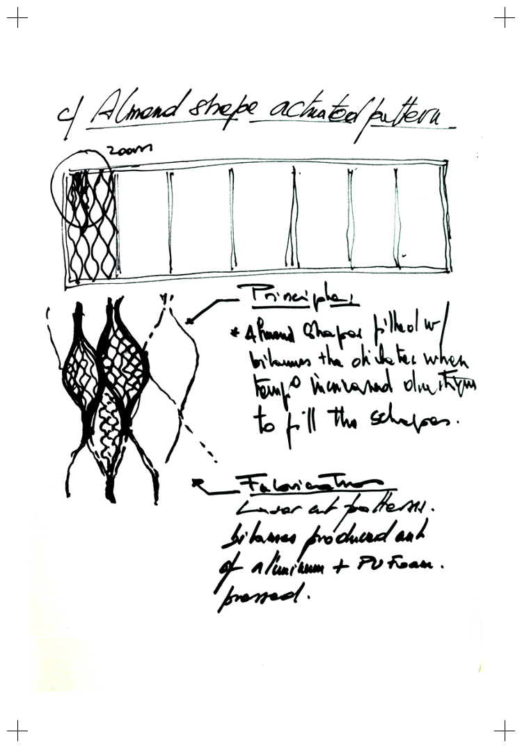
from the sun heat, according to the behavior of a heat reacting, biomorphic alloy material.
The almond shapes are filled with dielectric alloy filaments that expand when temperature increases up to the point they fill the shapes. The prototyping can be done with dielectric alloy laser cut patterns produced out of aluminium and PU pressed foam.
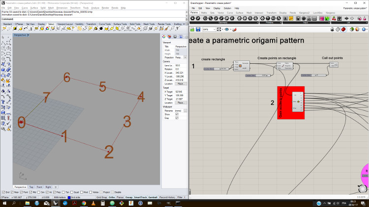
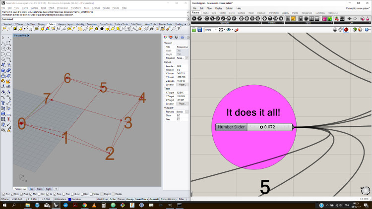
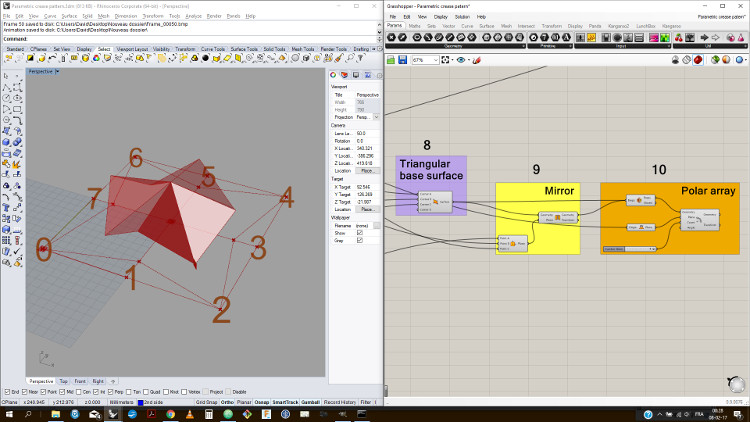
I experimented on a facade actuation system trough an exercice on Rhino 3D software with an origami exemple.
This study has been developped in the assignement Week 2.
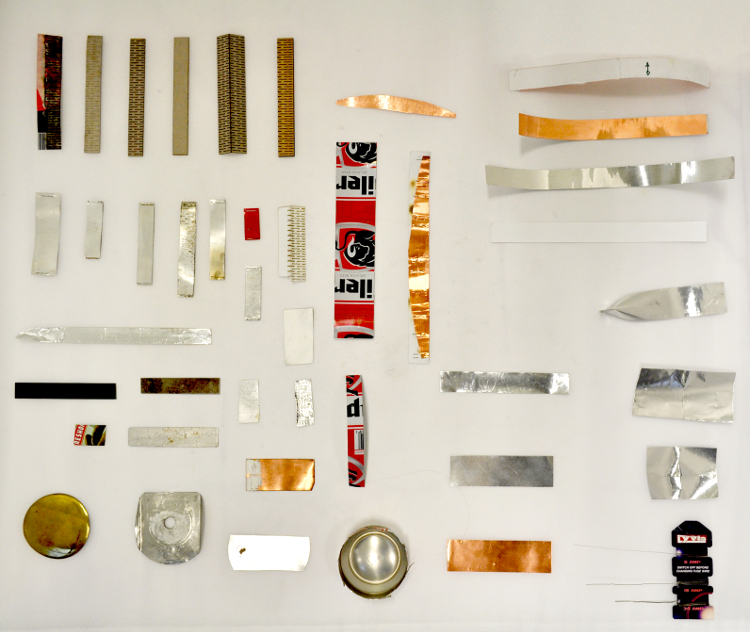
2.3. Material behavior studies
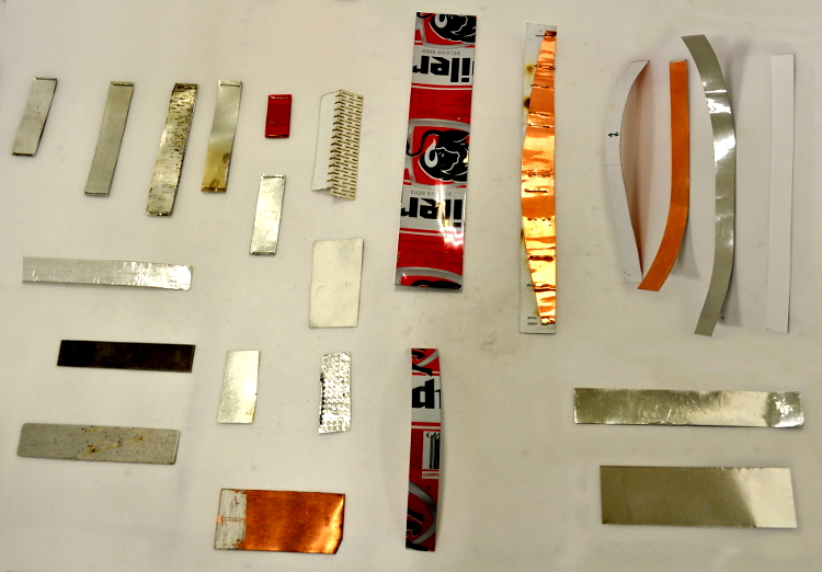
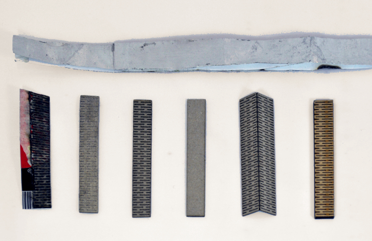
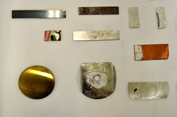
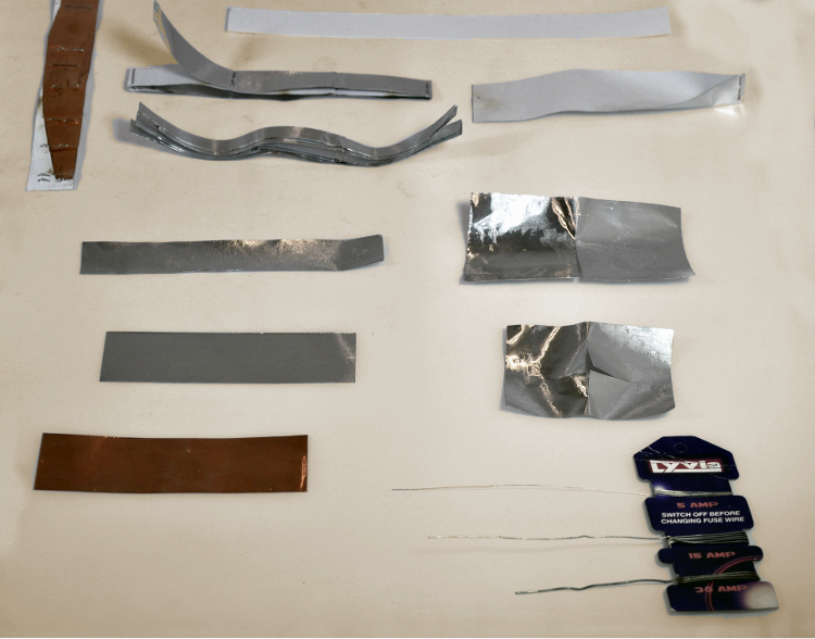
I started exploring the electric alloy materials trough different combinations.
I selected different samples and started to work on their behavior while heated.
The sample board shows that the metallic reactions weren't effective except for the aluminium sheets.
The cardboard and the timber samples didn't react well. The paper fixed to an aluminium sheet was the most effective combination.
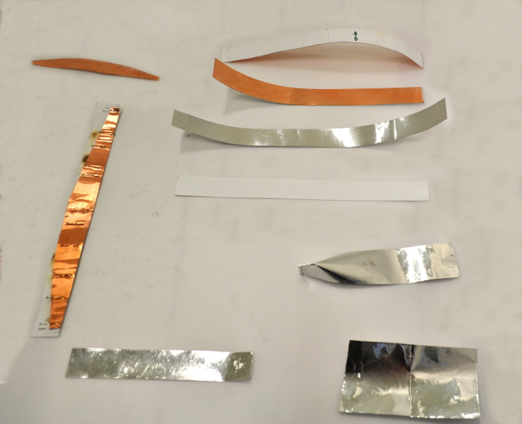
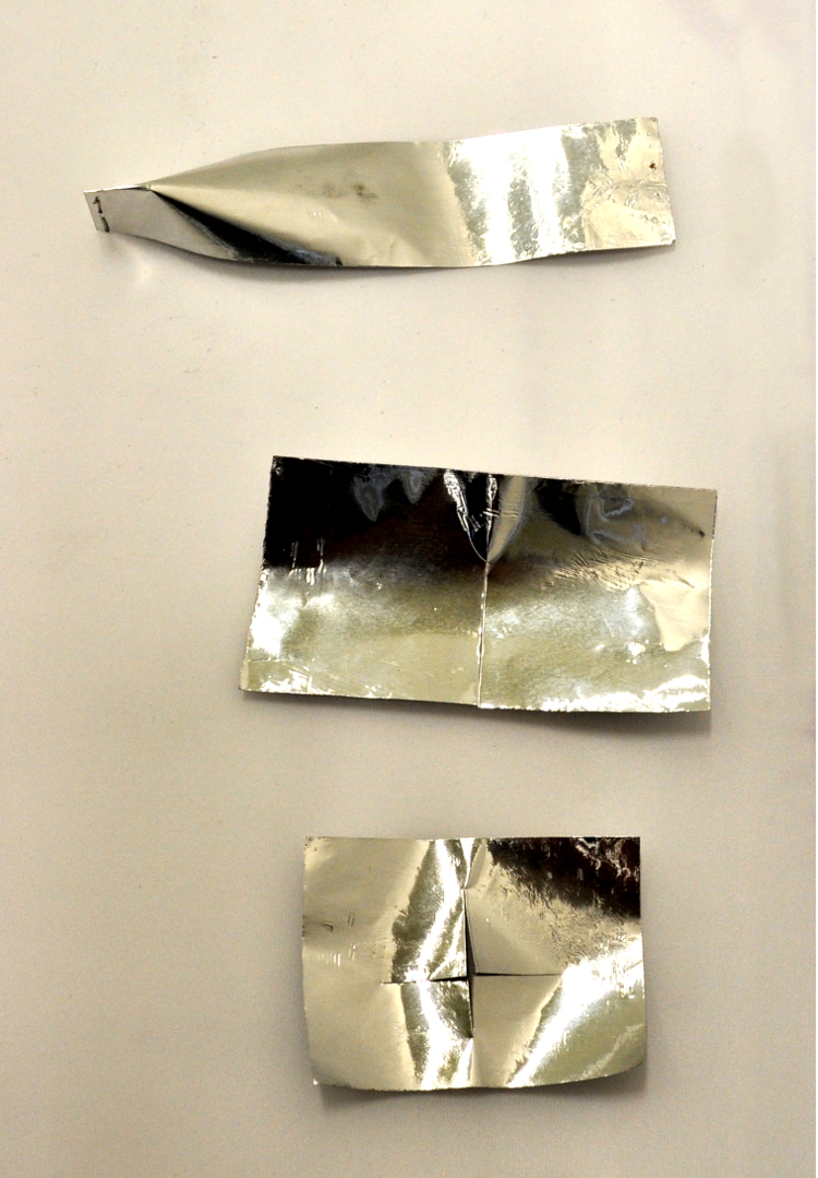
Having chosen the material combinations for my prototypes, I started exploring different shapes and forms that allow a better movement.
On top of that, I had a look at different methods to fix the facade louvers.
I realised that for a dielectric alloy material to move; only one side / point, should be fixed. Otherwise it prevent its movement.
3. THE ELECTRONICS
3.1. Schematics/ layout:
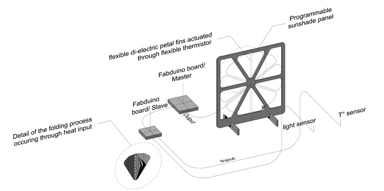
I designed a schematic layout which would monitor the temperature and lighting conditions on the dielectric alloy material facade.
3.2. Circuit for Final project:
I have been working on electrical exercices throughout the Weeks 10 & 13 assignements.
Hardware I have been using:
/ 1. LCD monitor and shield,
/ 2. Sensor for temperature an humidity,
/ 3. Light sensor,
/ 4. Board (modified satcha kit),
/ 5. Usb micro cables,
/ 6. FTDI module,
/ 7. ISP module,
/ 8. 1 power supply 12V,
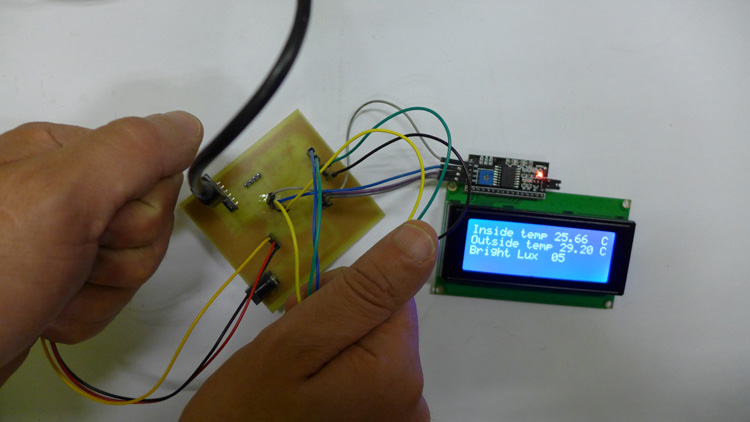
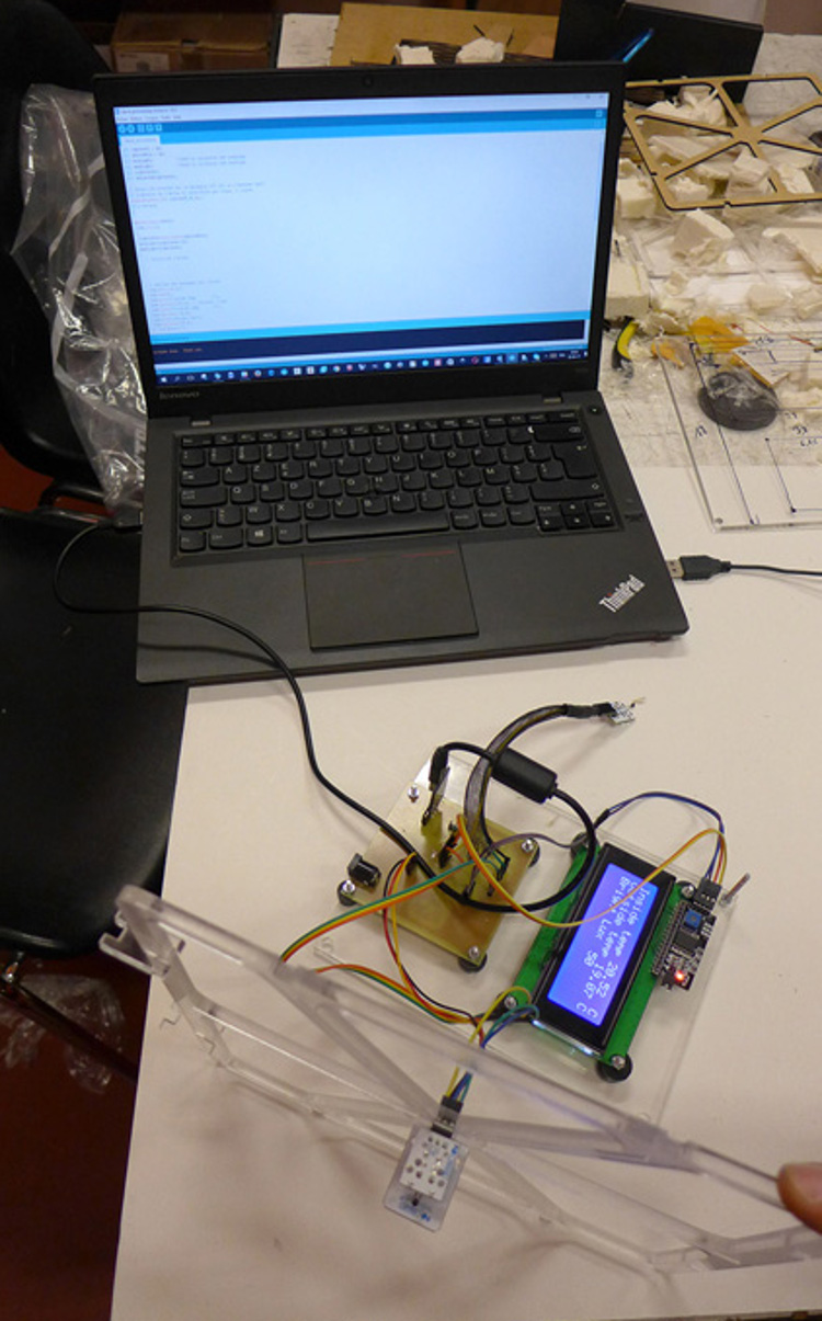
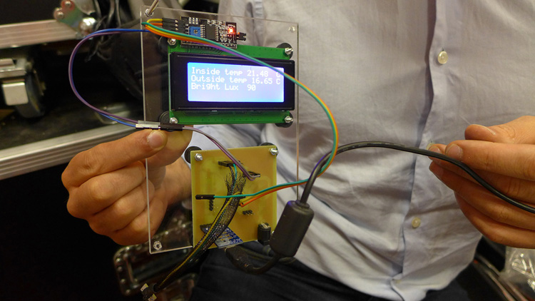
3.3. Working tests:
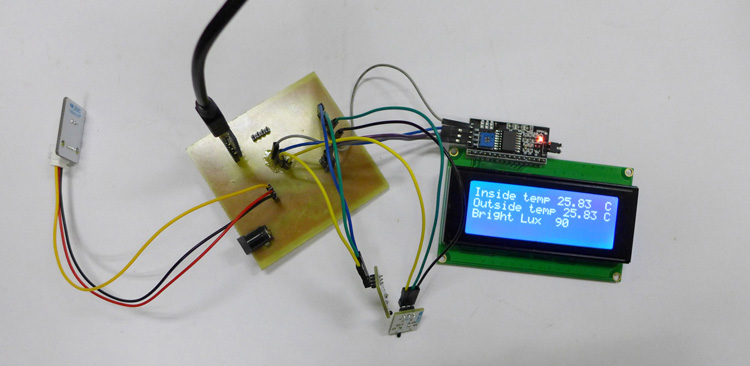
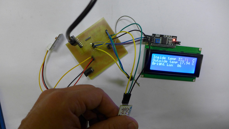
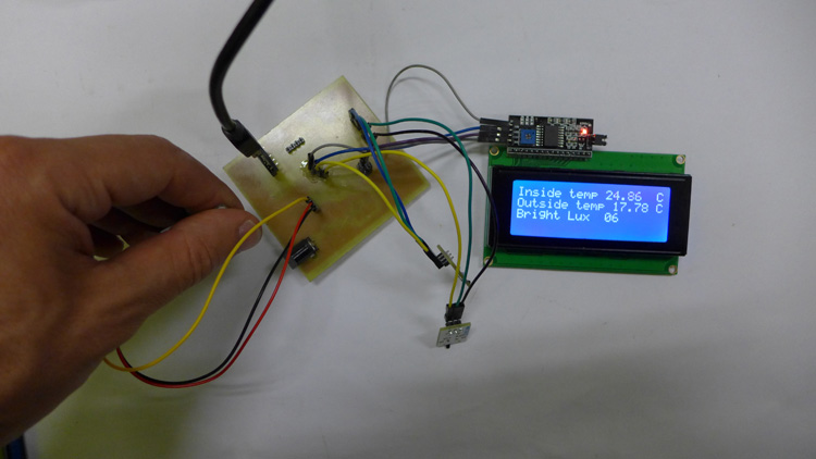
I have done a serie of successful tests with light et heat sensors.
Test 01: variation of the inside temperature log when the sensor is heated.
Test 02: variation of the brightness log when the sensor is covered.
Test 03: variation of the outside temperature log when the sensor is heated.
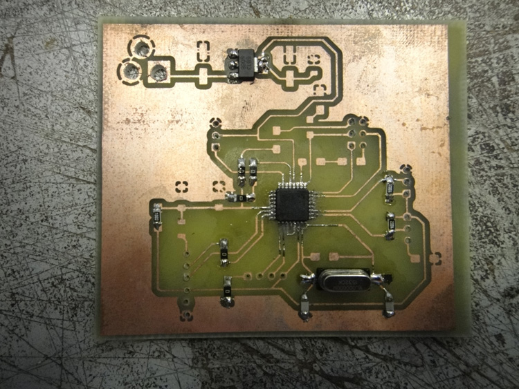
3.4. My own board:
I have designed and produced my own board based on a Satsha kit.
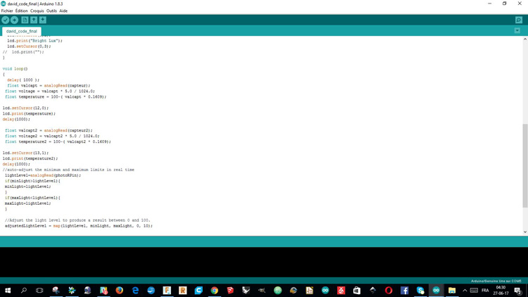
3.5.Code:
I have been adapting the code I used in Week 13 assignement.
                                    #include
                                   #include
                                   int capteur = A1;
                                   int capteur2 = A2;
                                   int photoRPin = A0;
                                   int minLight;          //Used to calibrate the readings
                                   int maxLight;          //Used to calibrate the readings
                                   int lightLevel;
                                   int adjustedLightLevel;

                                   // Ecran LCD branché sur la backpack LCD I2C (a l'adresse 0x27)
                                   // Dimension de l'écran 20 caractères par ligne, 4 lignes
                                   LiquidCrystal_I2C lcd(0x3F,20,4);
                                   void setup()
                                   {

                                   Serial.begin(9600);
                                     lcd.init();
                                   {
                                    lightLevel=analogRead(photoRPin);
                                    minLight=lightLevel-20;
                                    maxLight=lightLevel;
                                   }
                                     // Initialize l'ecran


                                     // Affiche des messages sur l'ecran
                                     lcd.backlight();
                                     lcd.home();
                                     lcd.print("Inside temp        C");
                                     lcd.setCursor(0,1); // colonne, ligne
                                     lcd.print("Outside temp       C");
                                     lcd.setCursor(0,2);
                                     lcd.print("Bright Lux");
                                     lcd.setCursor(0,3);
                                   //  lcd.print("");
                                   }

                                   void loop()
                                   {
                                     delay( 1000 );
                                     float valcapt = analogRead(capteur);
                                    float voltage = valcapt * 5.0 / 1024.0;
                                    float temperature = 100-( valcapt * 0.1609);

                                   lcd.setCursor(12,0);
                                   lcd.print(temperature);
                                   delay(1000);

                                    float valcapt2 = analogRead(capteur2);
                                    float voltage2 = valcapt2 * 5.0 / 1024.0;
                                    float temperature2 = 100-( valcapt2 * 0.1609);

                                   lcd.setCursor(13,1);
                                   lcd.print(temperature2);
                                   delay(1000);
                                   //auto-adjust the minimum and maximum limits in real time
                                    lightLevel=analogRead(photoRPin);
                                    if(minLight>lightLevel){
                                    minLight=lightLevel;
                                    }
                                    if(maxLight
4. PROTOTYPING
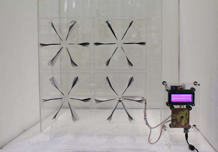
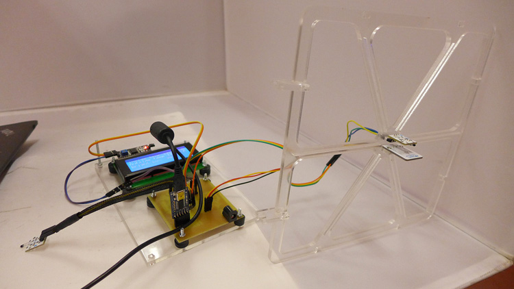
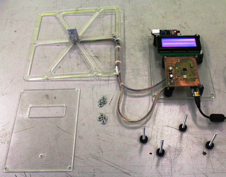
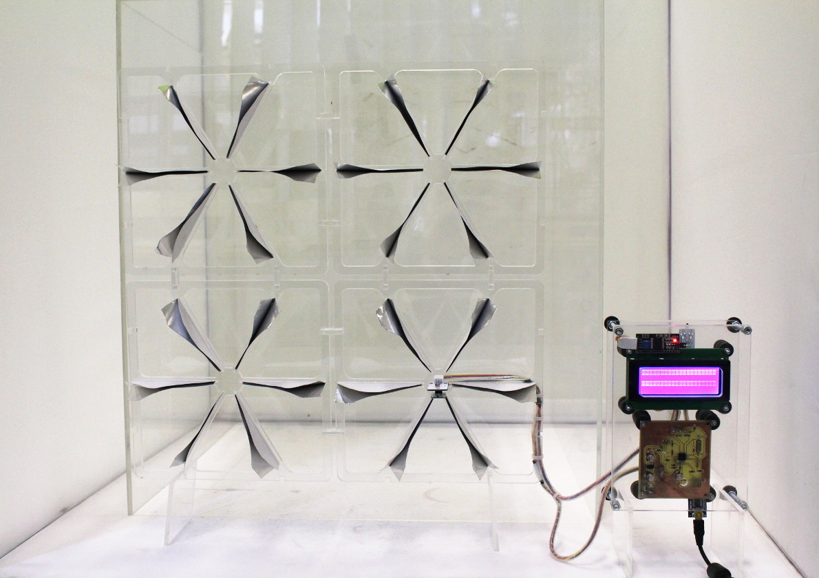
4.1. Overal view of the Final project:
I started working on 3 major elements for my prototype: the facade modules, the casing for the electronics and a
clean layout for the power supplied and the cabling. The facade module integrates a physical support in perspex
that houses the external temperature and lighting sensors and the dielectric alloy material petals. The prototype
is composed of 4 modules.
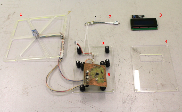
The complete prototype includes the following components:
/ 1. Sunshade modules including biomorphic petals, photo & temperature sensors;
/ 2. Interior temperature sensor;
/ 3. lcd screen for displaying interior and, exterior temperature & brightness level;
/ 4. Front casing;
/ 5. Back casing;
/ 6. Circuit board.
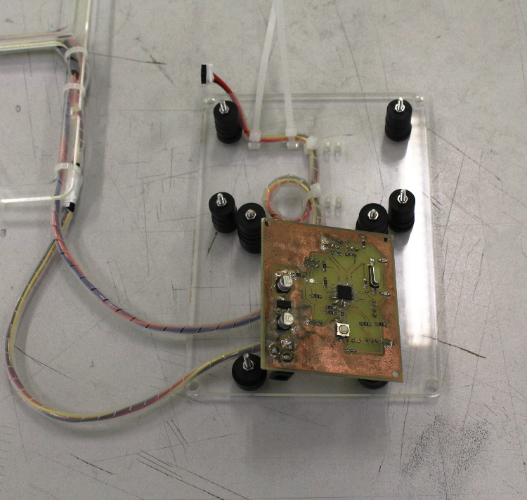
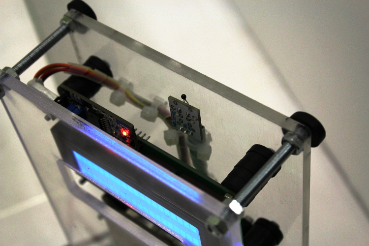
4.2. Electronics:
Step 1: Making sure the electronics is working.
The first step towards building a fully working prototype is to make sure that the electronics and the dsiplay
is working properly.
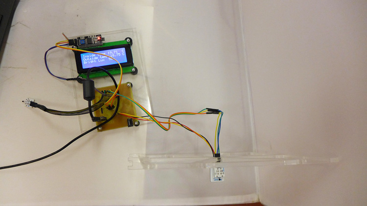
I therefore started design an initial casing to test foortprint of the prototype and make sure everything will
nicely into it.
That allowed me to fix properly the board, the display, the temperature sensor, and the FTDI port ont the back face
of the casing I designed, and to verify the casing footprint capacity. It was only after doing this, that I was able
to connect all the wires and test my circuit integration.
Now that I have a fully working test, including my casing and the wired module, I can go back to the drawing board
to improve the wiring integration and the overal ergonomy of the installation.
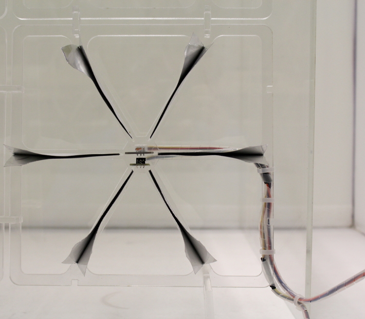
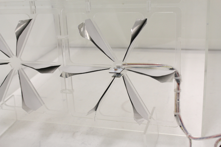
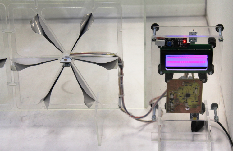
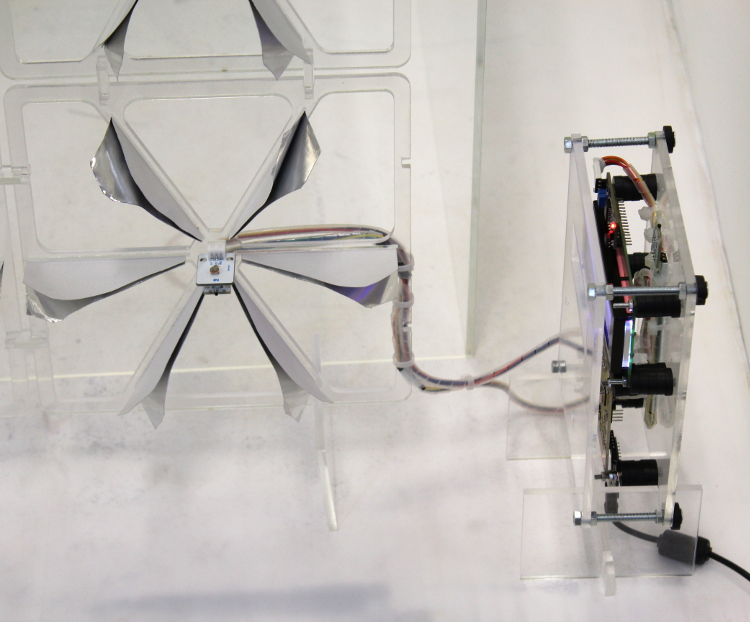
4.3. The modules:
Overal view of the final modules including the petals and the cabling: the prototype is composed of 4 modules
of which one includes the photo and temperature sensor. Project is designed to be fit on eisting building façades,
and is therefore going to heavily exposed to weather conditions (UV's, rain...). I therefore went for perspex as
a choice of material for my Final project, since it is easy maintainace, longlasting, resisting to tuff weather
conditions and finally very nice looking and light weight.
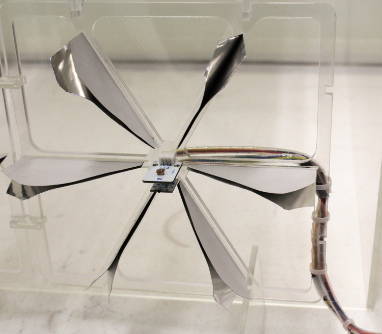
Detailed view of the module containing the photo and temperature sensor: this view also shows that I looked at
integrating the cabling in such a way that I dont end up with wires all over the module and to make sure it doesn't
prevent the petals from oprerating.
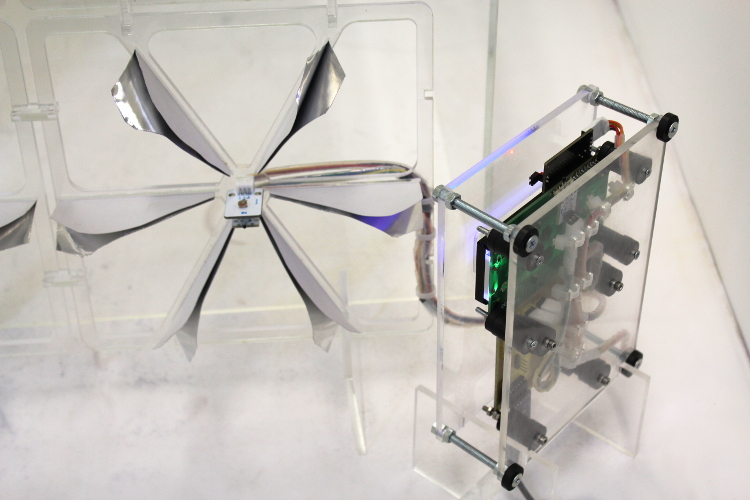
The module was studied to be as flexible as possible:
The module embarking the sensors implied some cabling, a special care was taken tighten it and to embed it as much
as possible into the frame of the module
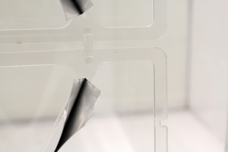
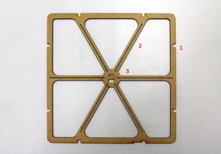
The modules are connected to each other as a pressfit kit, no glue is requiered. All the grooves were studied to fit tight
together, this results into nice, simple and minimal connections for assembling the modules together.
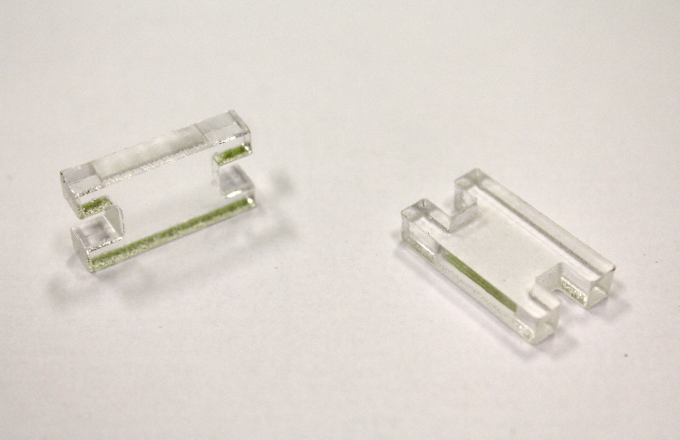
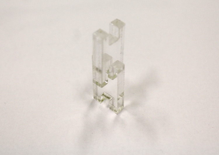
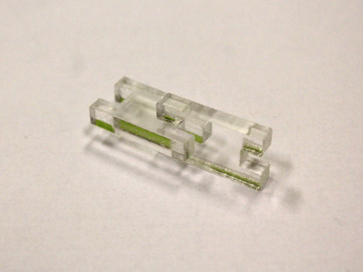
Detailed view of the pressfit hinges.
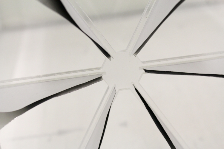
The petals are indented and glued into radially branched, purpose made slots.
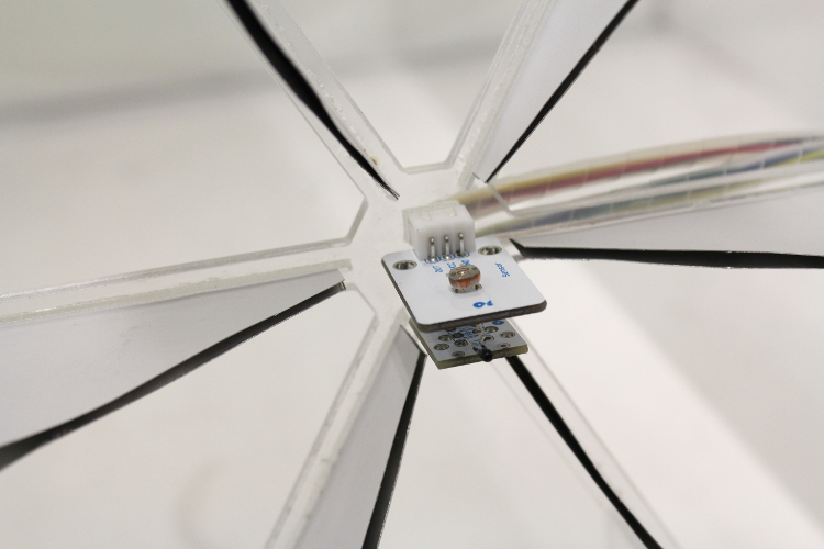
The two sensors are tightly inserted into custom cutouts designed specifically for that particular module.
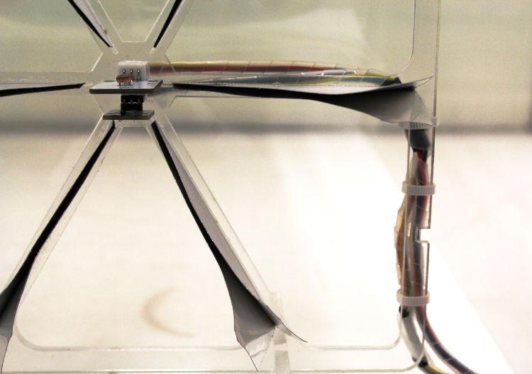
Detailed view of the cabling dressign and integration.
4.4. The casing:
The electronics are integrated in a purpose designed perspex casing.
Now that I have a completely working test module including an initial test design for the casing, I can
improve the design of the casing to integrate the wiring into it.
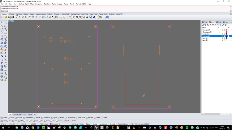
This is a screenshot of the new design for the casing, that I will be laser cutting.
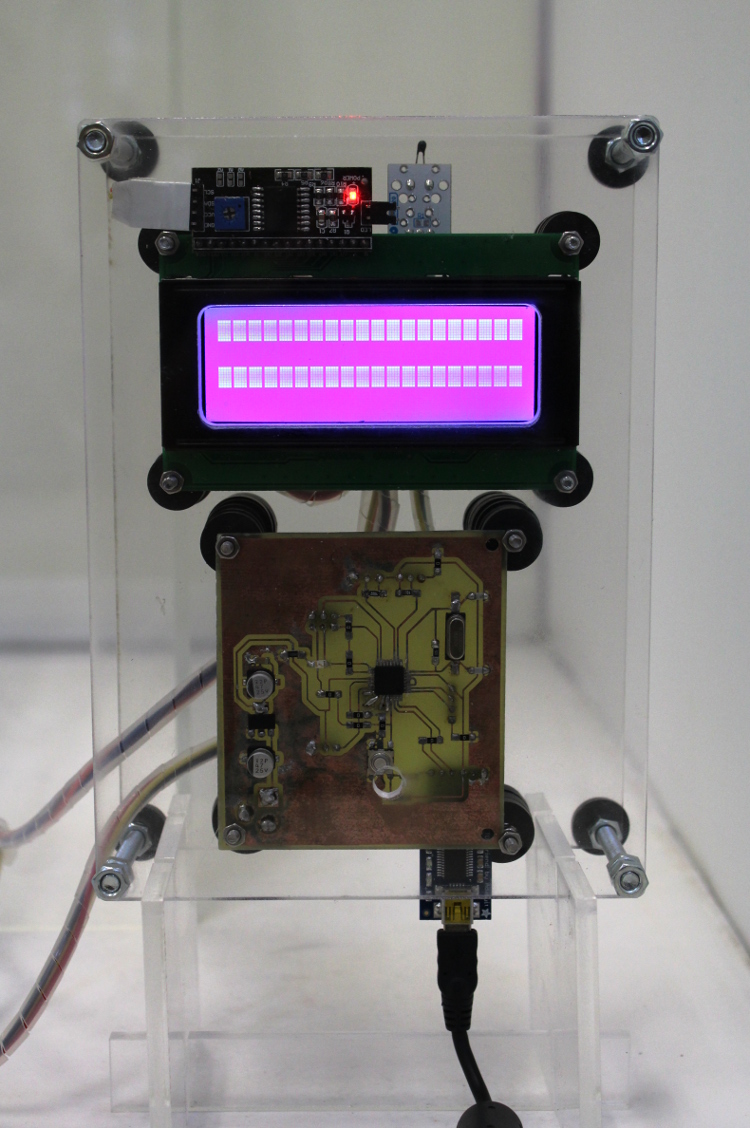
Overal front view of the completed casing.
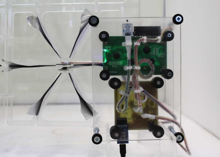
Overal back view of the completed casing.
The new design of the casing implied to hide a maximum of fittings towards the back of the casing.
That implied first to lift up the board and the display to pass all the wires and connections behind them.
In ordrer to achieve that, I had to make use of a number of spacers and bumpers to hold them.
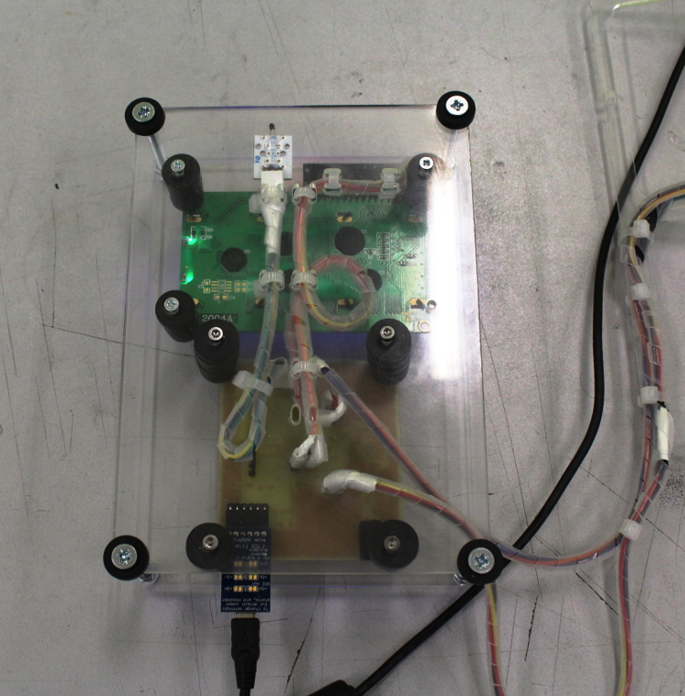
I also had to make sure to sort out the wire problem, I therefore had to laser cut a series of cutouts
on the back face in of the casing in order to be able to tighten properly on top of it. The cabling was also
dressed with transluscent PET coil wire in order to assemble it and to integrate within the overal desgn.
4.5. Design ergonomy:
The overal design of the installation was carefully studied to make it accessible and confortable to maintain,
modify or upgrade the system.This as much valid when it comes to adding axtra modules, as it is when it comes
to modifying the layout of the circuit board, or to adding extra sensors or end effectors
(FTDY port, sensors, shielsds...). Finally a hole was
laser cut into the front face to acces the reset button
The spacers allow to easily remove the front face or to increase the space within the box if one needed to add
extra components.
The connections are easily accessible without having to open the casing.
The same goes for most of the sensors or other input devices. The wire connectors are carefully grouped in
bunches and tighten to the frame to make it easy to remove any input.
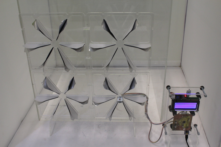
4.6. Final project shots:
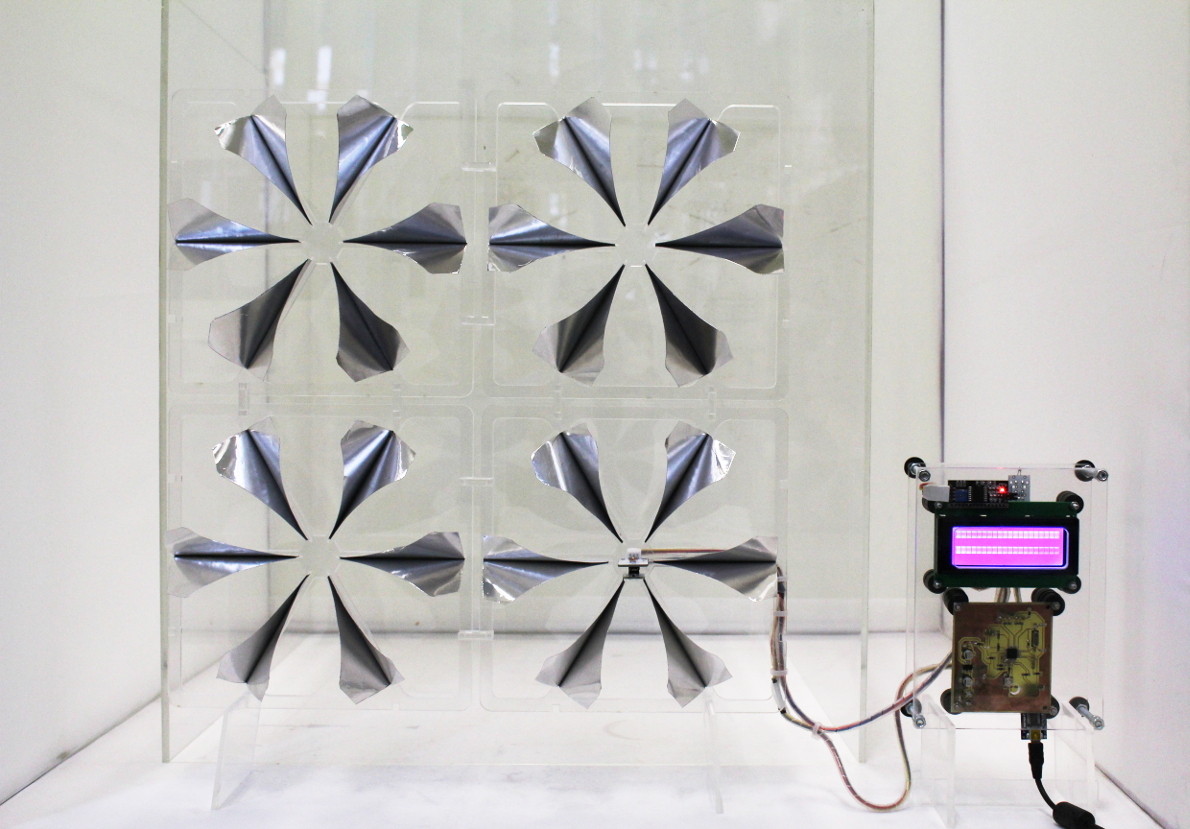
This is a front view of my Final project with the petals closed.
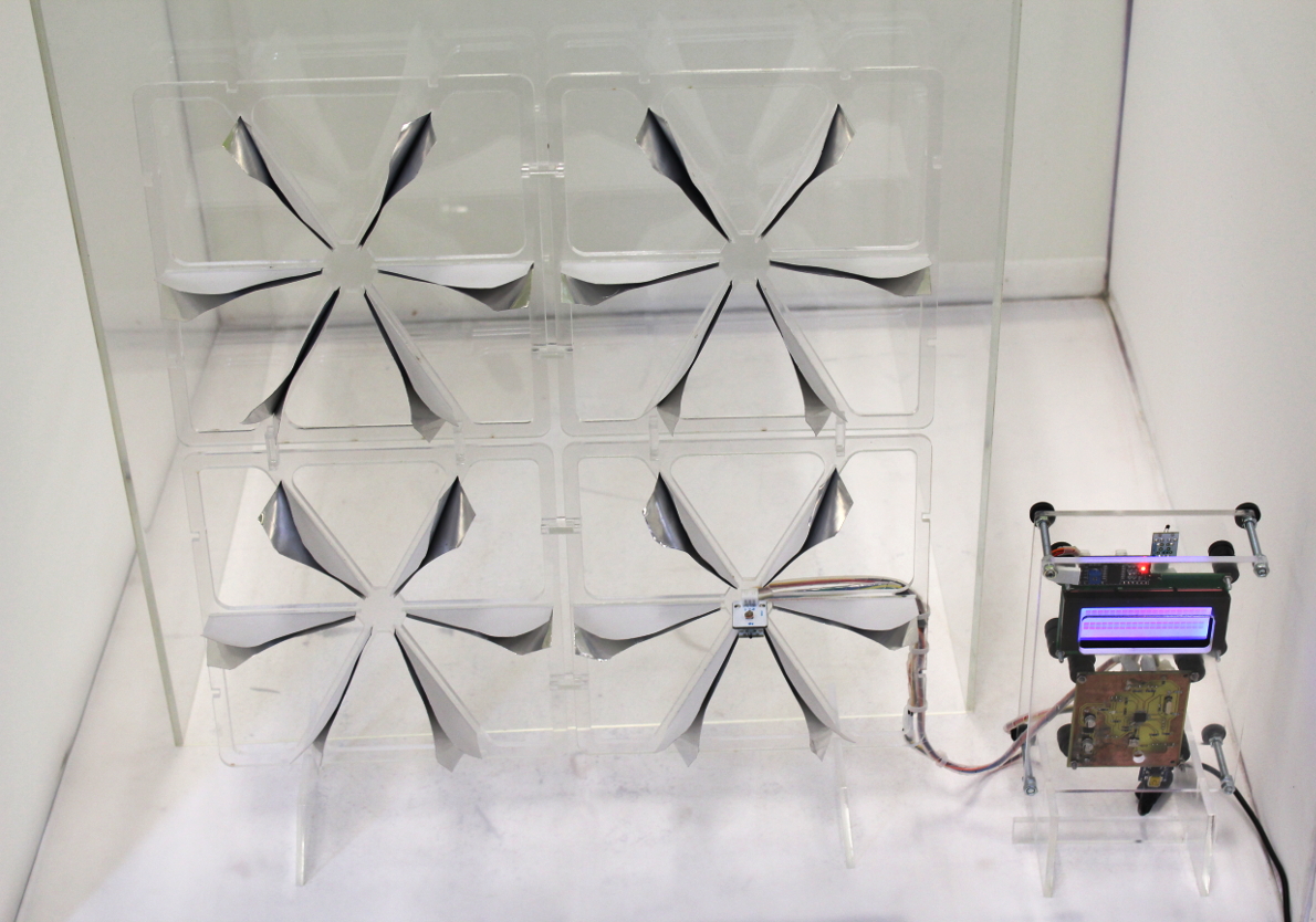
This is a front view of my Final project with the petals closed.
This is a front view of my Final project with the petals partially open.
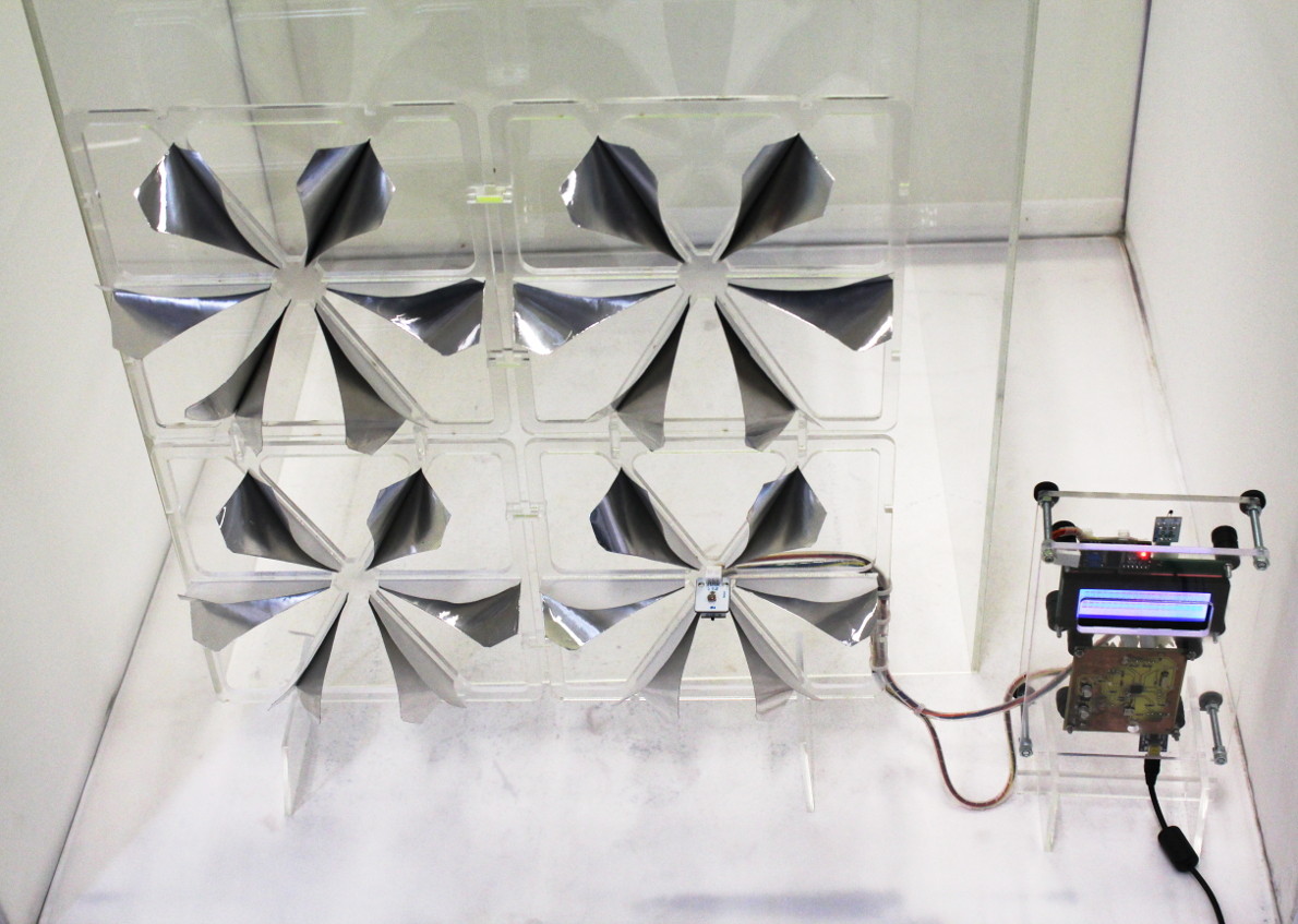
This is a front view of my Final project with the petals partially open.
4.7. Final Project outcomes and aknowlegments:
Superfold project was initiated as part of my Fab Academy work assignments.
During that time, Fab Academy allowed me to develop it:
/ 1. up to a level where I can draw conclusions as to continue developping it beyond the level of initial prototyping and prove of concept.
/ 2. and gave me a set of tools to make sure my project is well archived and that my design can be further developed.
/ 3. as much as from a design and research prospect as from a social and ethical point of view.
Beyond the scope of the project, which as far as I'm concerned, is only a starting point, Fab Academy gave me an insight into so many other fields I always wanted visit and for
which I lacked the time or motivation. I now feel confident I can carry on some of the work I've been starting as part of my assignments (i.e.about electronics) and for which I'd ike
to take time to explore more in depht.
Finally and more importantly, as a teacher, I deeply believe Fabacademy is a great way of teaching and learning. On top of being a phenomenal empowering platform for learning, it is really
revoutionnary in the sense that it is providing the ressource of a world network of expert and knowlegde at the fingertip of each one of the students.
I would like to thank the Fab Academy, my instructors from Woma and Barcelona for helping me throughout the semester;
my fellow colleagues Victor, Denis, Michele and other experts in their own rights for helping me and supporting during the difficulting times.
And finally a very special thank you to my wife and friends.
5. FINAL PRESENTATION
5.1. Final project - slide:
5.2. Final project - movie:
- Date: February to June 2017