Week 4 - Electronics production
1. Make an in-circuit programmer by milling the PCB, then optionally trying other processes David Andy Valentin Ali Zaerc Brian hello.ISP.44.cad board components traces interior hello.ISP.44.res.cad board traces interior inventory microcontroller crystal USB connector ribbon connector Zener diode jumper firmware.zip
- make clean
- make hex
- (sudo) make fuse (check programmer in Makefile, may need to repeat)
- (sudo) make program
- desolder SJ1 and SJ2
- make IDC ISP cable, connecting header pin 1 to pin 1, check wires
2. programming.
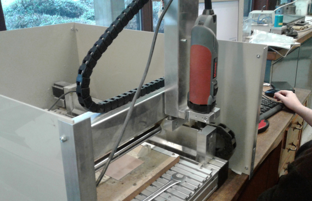
- CNC milling
- Soldering iron
- PCB
- Electronic components
Softwares :
- Eagle 8.01 a free software for circuit design used in parametric way
- Key cad 10 a free software for circuit design used in parametric way
- Fusion 360 a 2D 3D CAD CAM parametrica TOO
- FlatCAMFlatCAM lets you take your circuit designs to a CNC router
- Arduino IDE 1.6.12Free programing software for Arduino type circuit boards
Assignement
1. We designed ou circuit on Eagle.
It is a rather user friendly software.
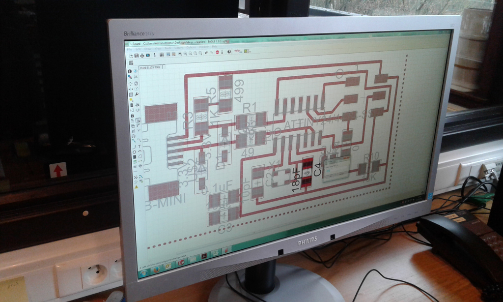
Board
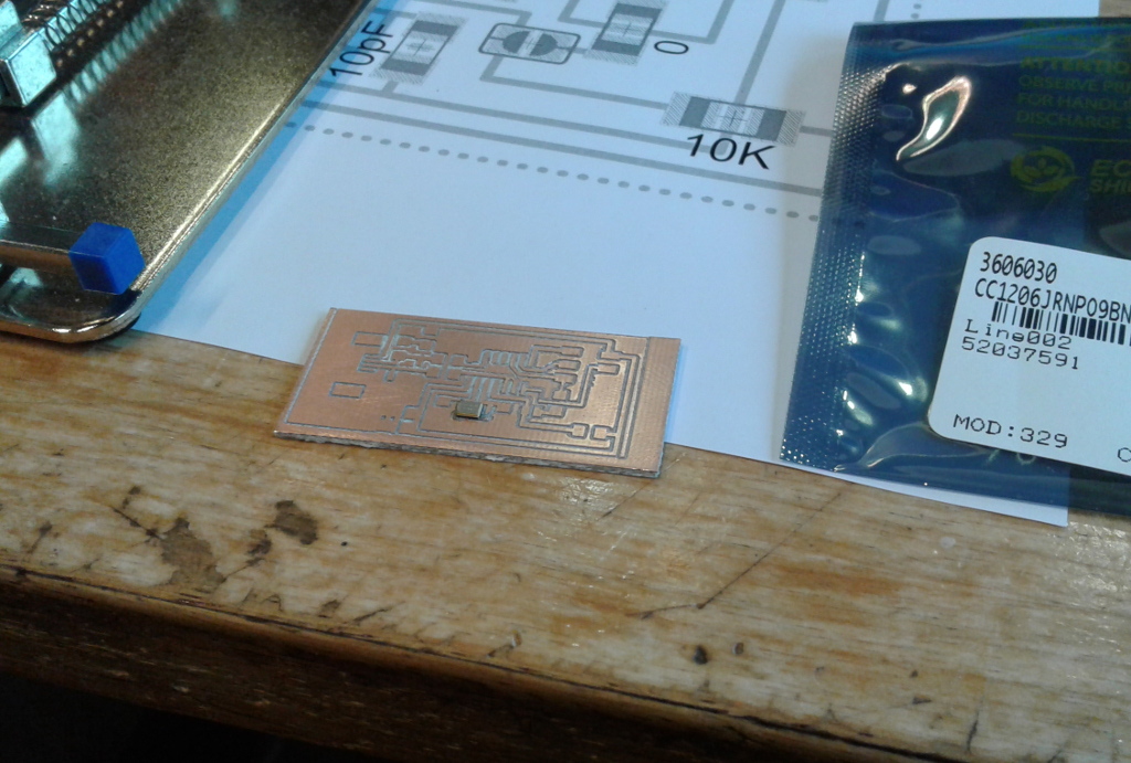
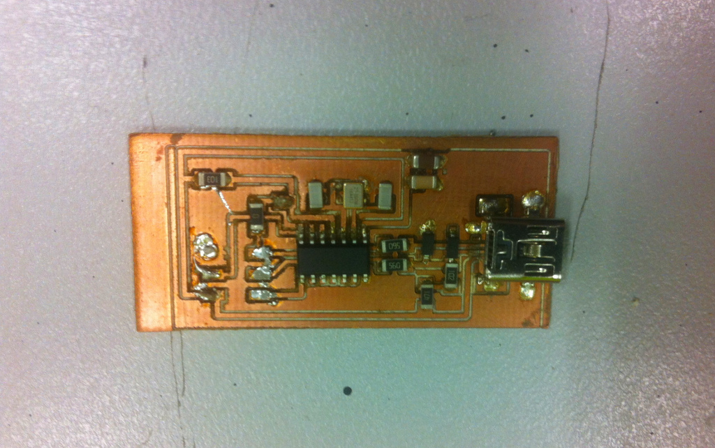
We initially went for SMD circuit board because components were easily available on the market, and we chose it under the advise of Denis lab technician...It was an interesting experience.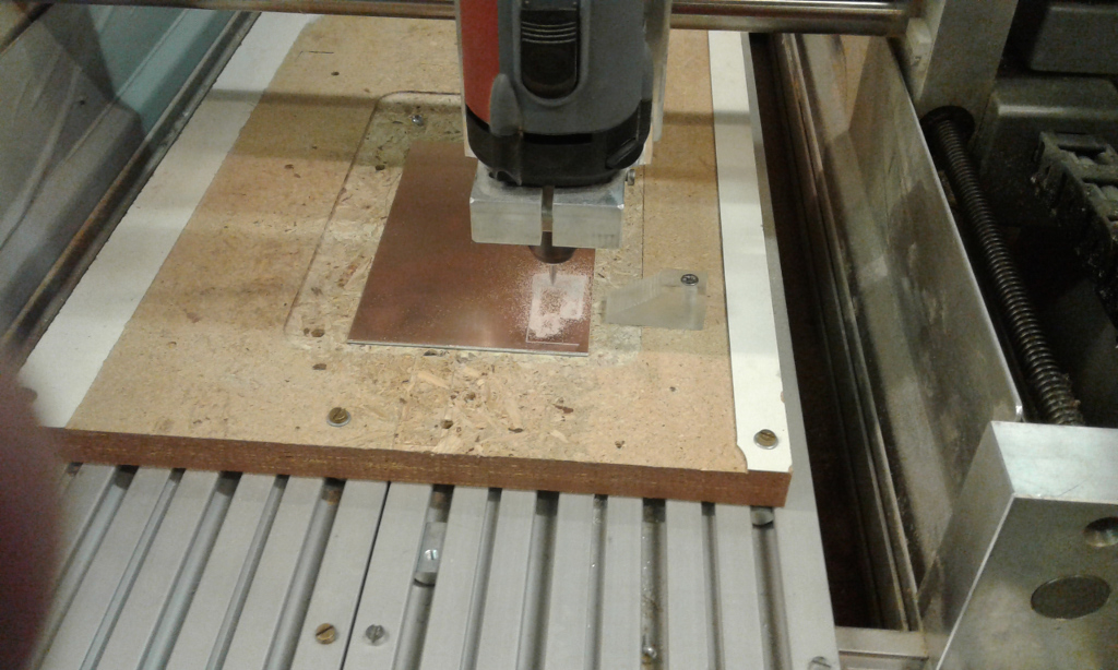
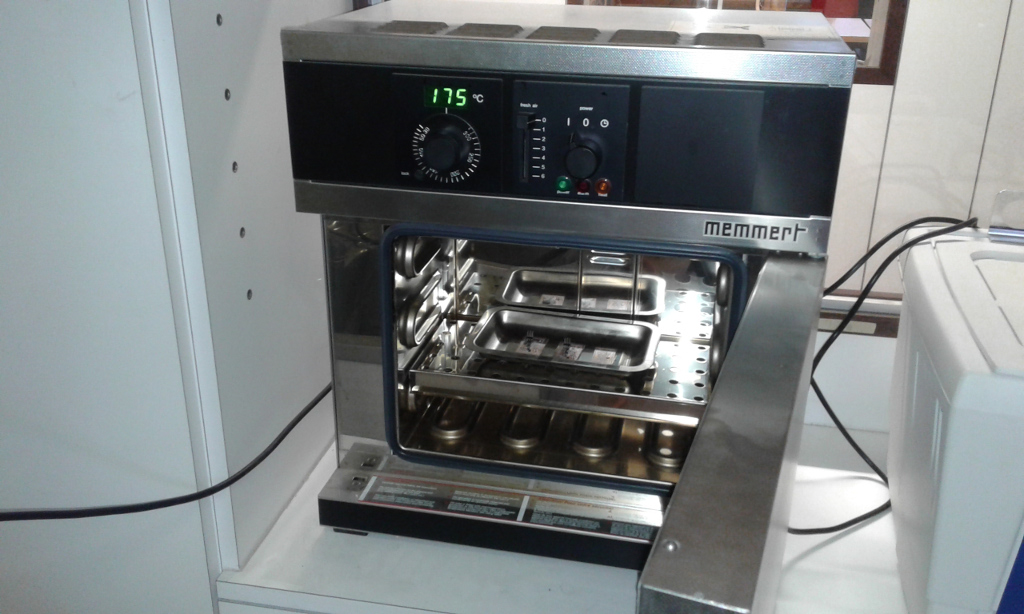
Since we had access to a hoven at Denis lab, we thought using soldering paste would be faster than just soldering...it was indeed very "clean job" but nothing really worked.
Since we had access to a hoven at Denis lab, we thought using soldering paste would be faster than just soldering...it was indeed very "clean job" but nothing really worked.
We generally use processing chips AT mega 25/60 that include bootlog, since this particular job didn't need such a complex board, we were advised to use the Atmel tiny 45. so we had good fun in building an in programmer circuit that didnt include any
After a couple of days (thursday & friday) of trial with no fortune in getting our circuits to work, we got back to the milling board.
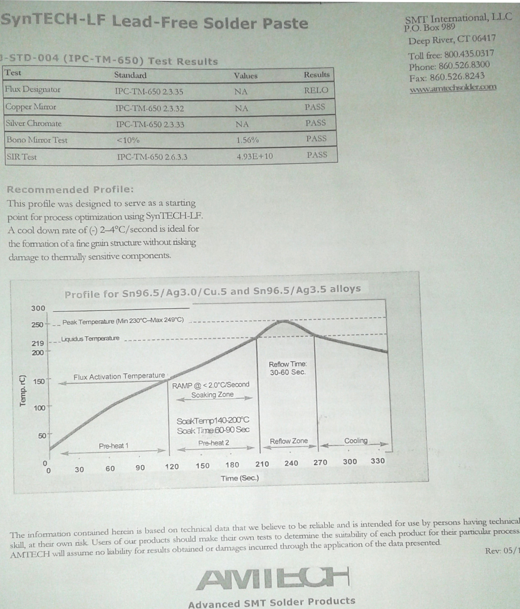
to cook the pizza we use thermal ramp
here we have the first board with crystal that we have rotate of 90 °
we continue with test
we have make a big poketing to have a good Z axis
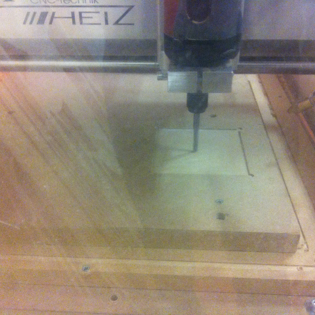
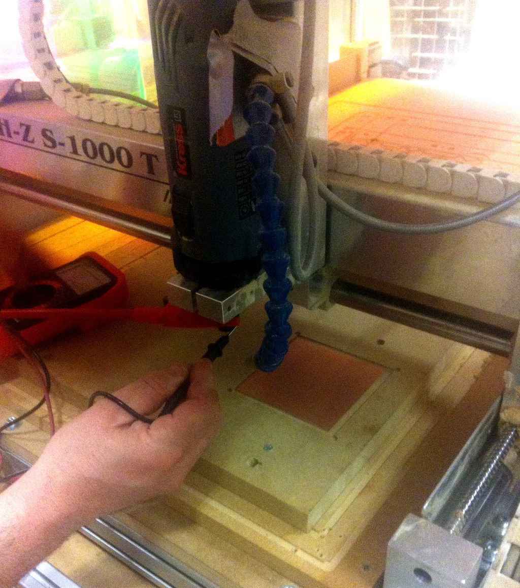
we use multimeter to find the Z zero with hight precision
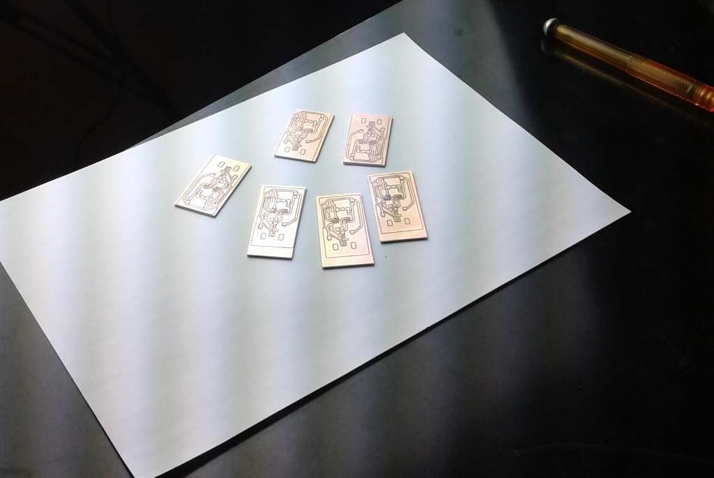
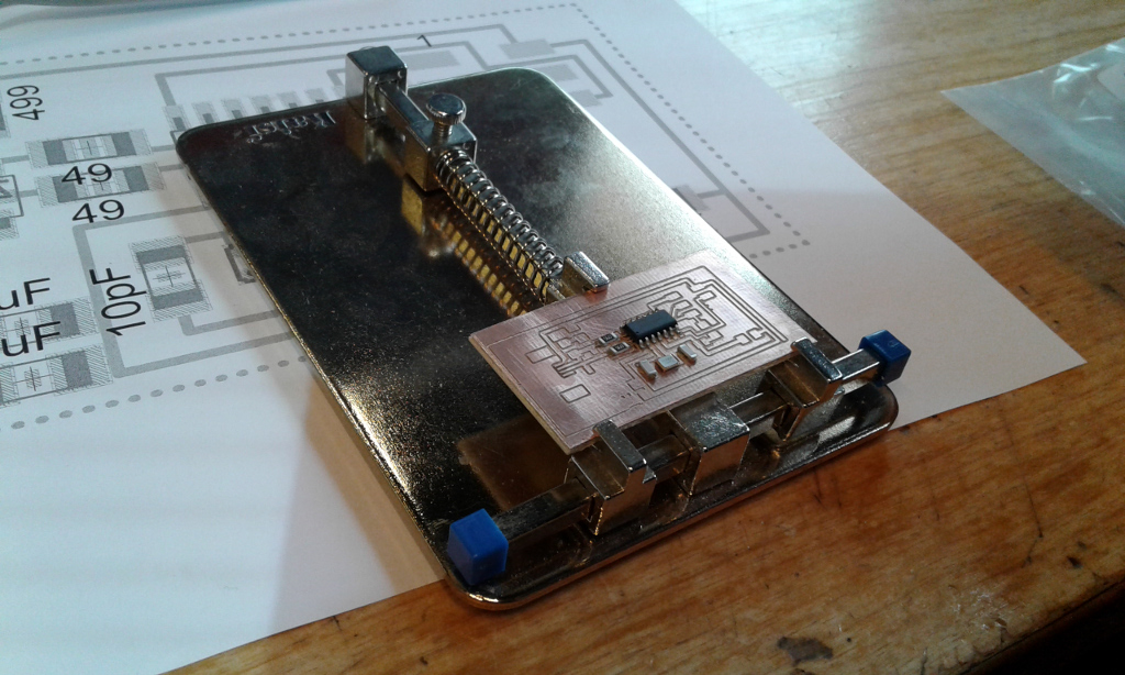
we make a second board but we make ten job in same time and we exchange top view with botton view of attiny85
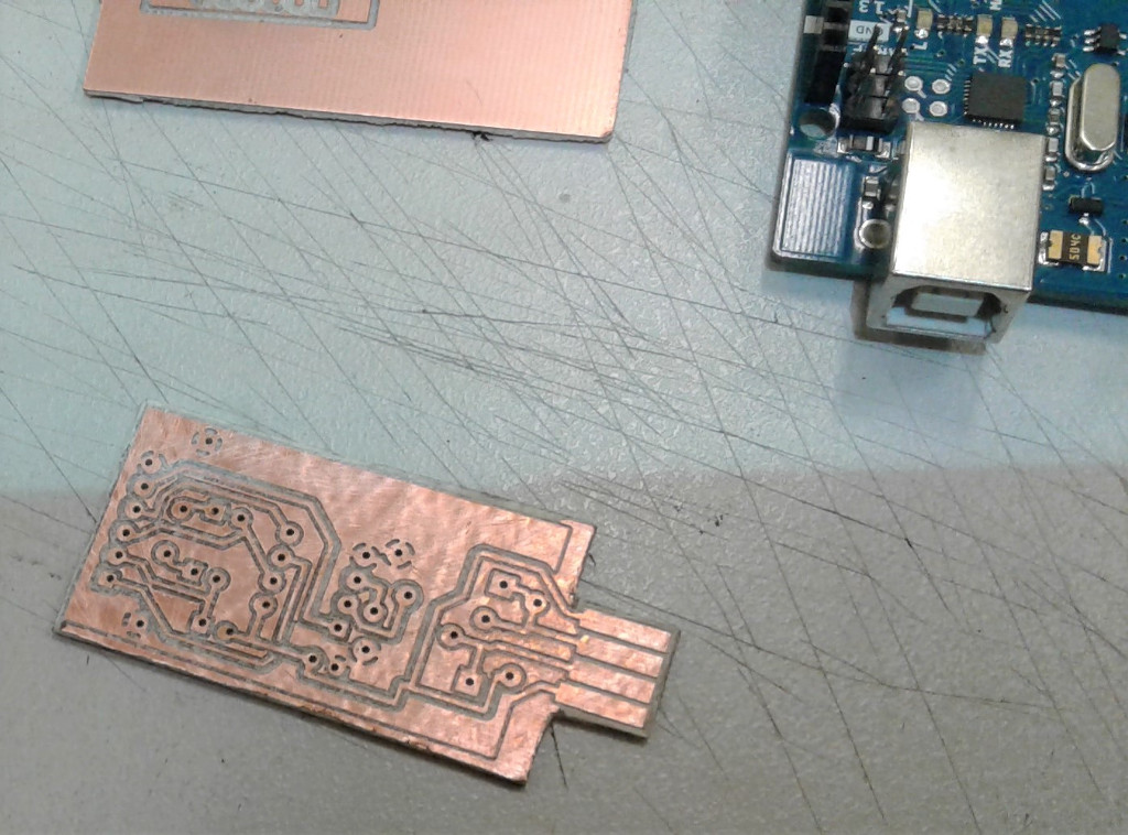
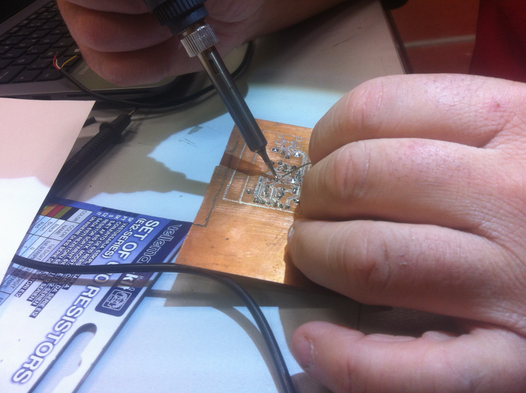
no problem We solder in the botton face
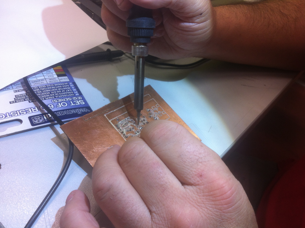
i solder zener resistor
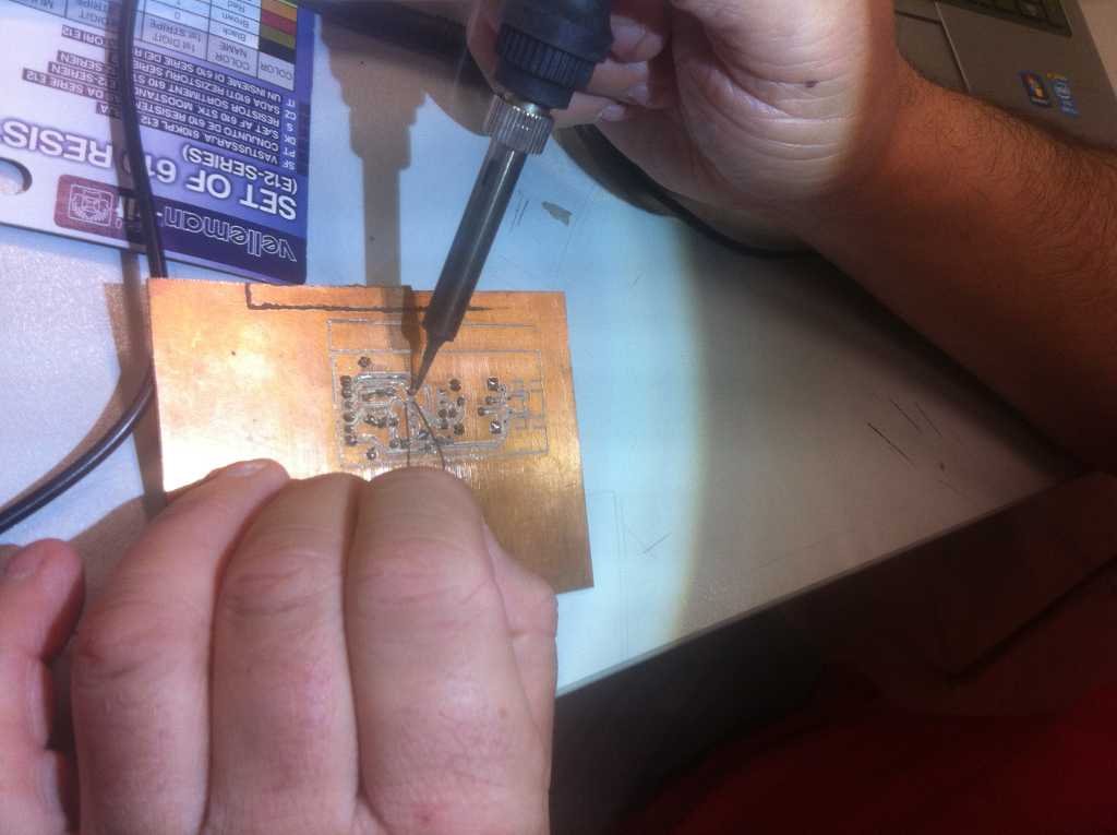
good looking for a board made in little time
is simple face I need a bridge
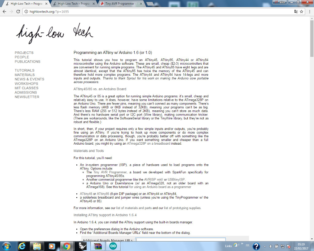
I download last version of arduino IDE and I add the files of attiny45/85 to the configuration
I use a arduino uno that have a bootloader to program attiny and I charge the program blink and I modify the duty cycle

my animation is very little in Kbyte
It turn!!