Week 3 - Computer-controlled Cutting
Assignments
- cut something on the vinylcutter
- design, make, and document a parametric press-fit construction kit, accounting for the lasercutter kerf, which can be assembled in multiple ways
Cut something on the vinylcutter - Log
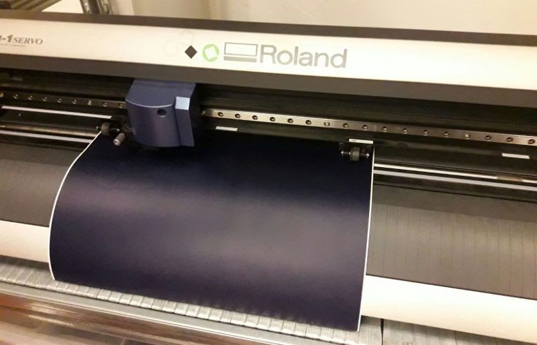
Opendot has a Roland CAMM-1 Servo GX-24 vinylcutter. This device can cut all conventional materials like vinyl, polyester, polyurethane and sandblasting foil.
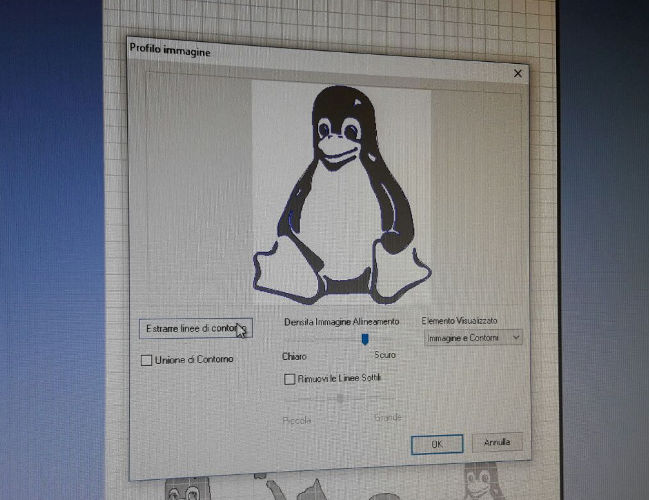
All Roland cutters are supplied with the CutStudio software. This allows you to quickly and easily enlarge, reduce, move, rotate, and mirror images. You can also create simple designs, format text, and import images. Most important, you can import raster images and let CamStudio vectorize them automatically. The software supports color and grayscale images, but the automatic thresholding it's not alway the best solution. To obtain better results, I suggest to user black and white images (or to convert them to B&W using thresholding in GIMP - see week 2).
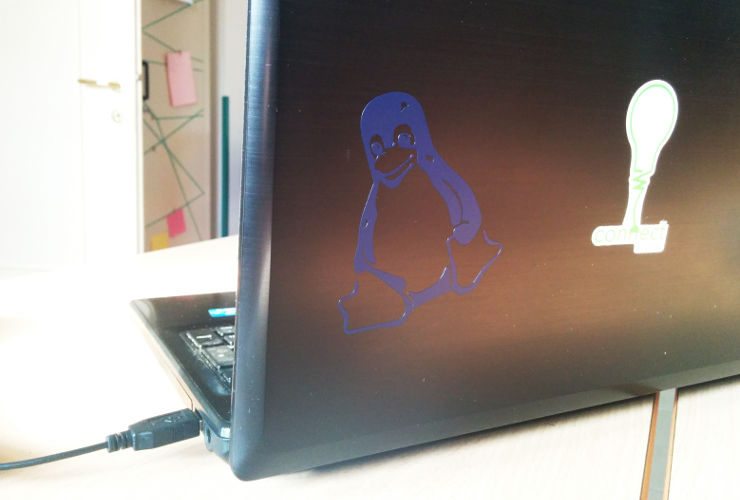
For my first vinyl cut I choose Tux - not just a penguin, but the mascot of the Linux operating system!
This week I used an existing drawing - during my final project I will design from scratch some logos and I will vinyl cut them.

I imported the image into CutStudio and I let it extract the contour automatically.
I run the job, and the cutter processed it in less than 1 minute.
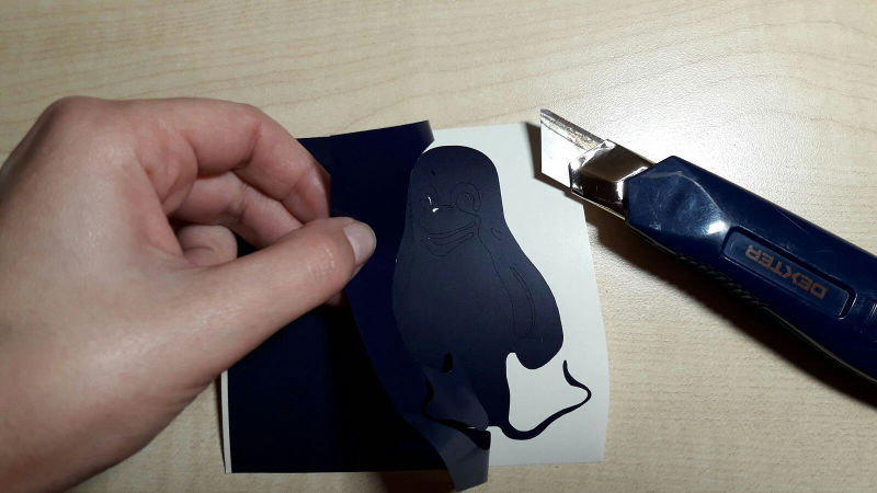
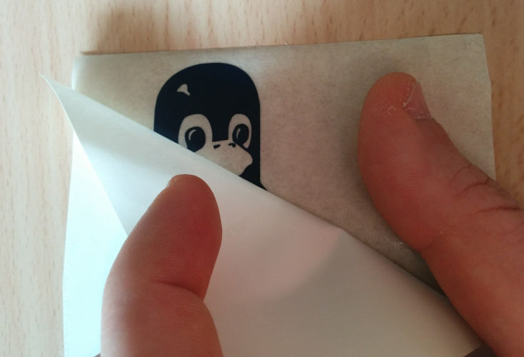
I weeded all of the excess vinyl, leaving the dark parts of the penguin.
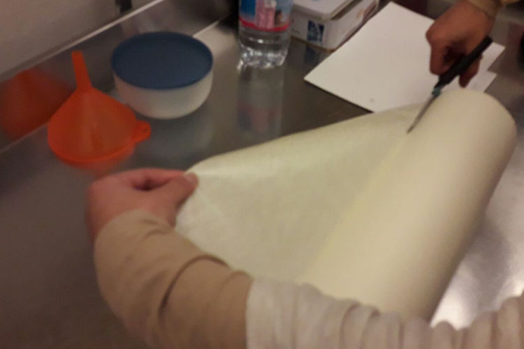
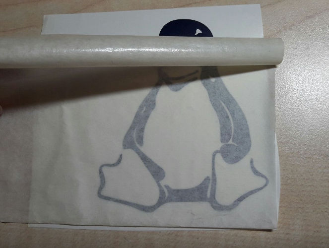
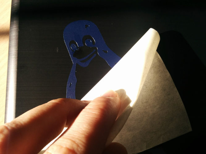
Next, I cut a piece of transfer paper roughly the same size as my piece of vinyl. The transfer paper is used to pick up the design and move it perfectly to the final surface; otherwise, it would be nearly impossible to peel it up and place it down by hand in exactly the way that it was designed and lined up.
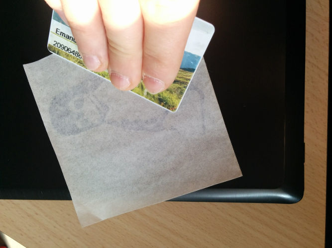
I moved the transfer paper on the vinyl and, using a gift or credit card, I scraped over the design to make sure the transfer tape was adhering to the vinyl nice and tight.
Then, I slowly started to peel up my transfer tape. Beware: peel slowly and be sure that the vinyl is coming off with the transfer tape!
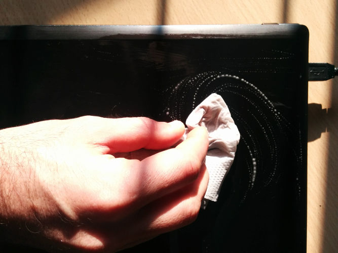
Before applying the vinyl, I washed the surface of my laptop with water and soap to make sure the vinyl will adhere evenly
I applied my design on my laptop pressing firmly down the transfer tape. Here, I suggest you to get out your scraper card again and score over the whole design to make sure that it adheres nicely.
Finally, I started to peel back the transfer tape, taking care not to pull up any part of the penguin.
Great! I transferred my first vinyl cut :-)
Cut something on the laser cutter - Log
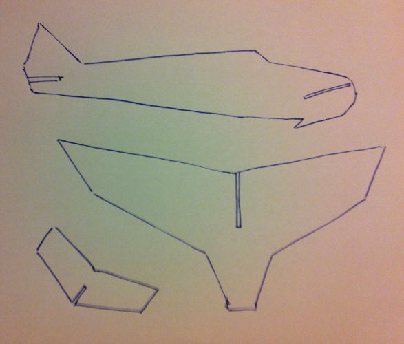
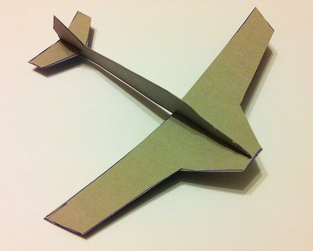
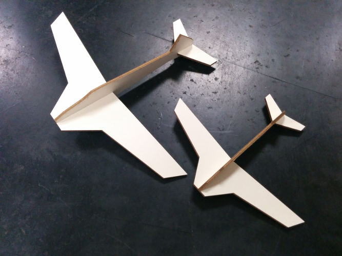
I designed a small airplane model as a parametric construction kit. Firstly, I designed it on the paper, just to get an idea of the proportion among the parts
Then, I drew it on a piece of used paper board and I cut all the pieces
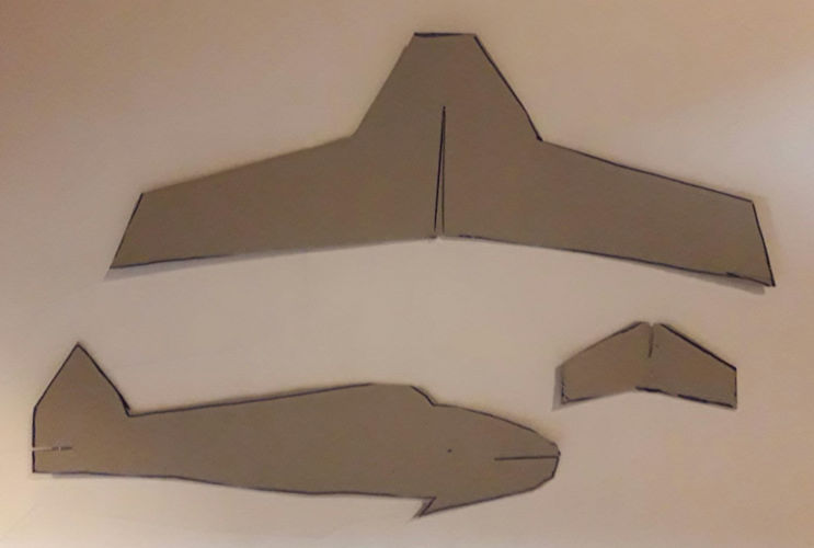
The assembled model looked nice, so I decided to move on!
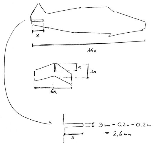
Before moving to CAD, I tried to define proportions among the the horizontal stabilizer, the fuselage and the wings. As you can see, I used the length of the half-lap joint on the rear part of the airplane as a reference (x) to scale the rest of the model - on the contrary, the width of the cuts for the joints is fixed. This number comes from the thickness of the material minus the kerf (actually is half kerf on one side plus half on the other side). Hence, for a 3 mm cardboard and a kerf of 0.4 mm, the width of the joints should be 2.6 mm (3 - 0.2 left half kerf - 0.2 right half kerf).
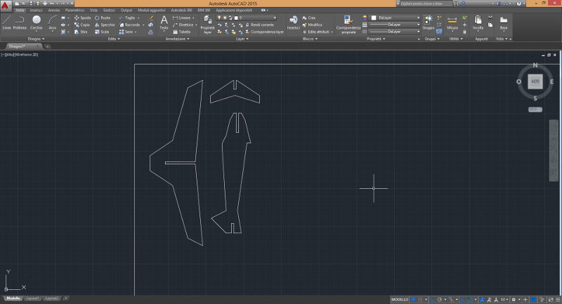
Helped by Cristiana and her knowledge of AutoCAD, I designed the airplane in parametric. As described above, the spacing within the junctions has been designed accounting for the kerf of the laser cutter hosted by the Polimi - Laboratorio Modelli - the technical specs of the cutter (in Italian only) are available here
First, I sketched the 2D design of my airplane in AutoCAD
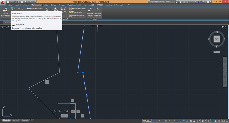
Then, I played a bit with the parametric features. The "Parametric" toolbar contains all the buttons for setting geometric constraints (perpendicular, aligned, parallel, identical, etc.). The "Automatic constraint" tool is really useful for beginners and for applying constraints to existing designs: it tries to identify automatically all geometric constraints based on the position among lines and shapes.
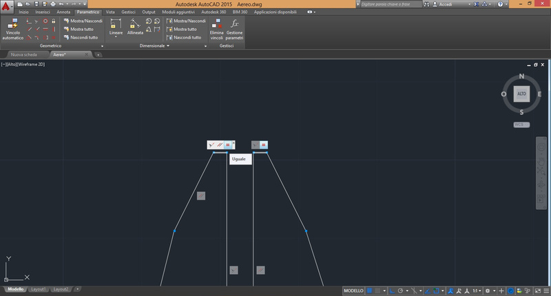
However, I my design was really simple, so I applied manually the parallelism constraints to the joint...
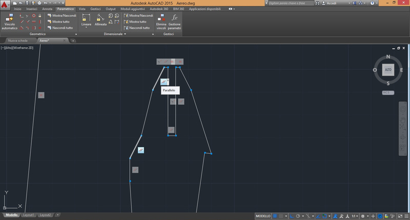
...and also I added an equality constraint for centering the joint.
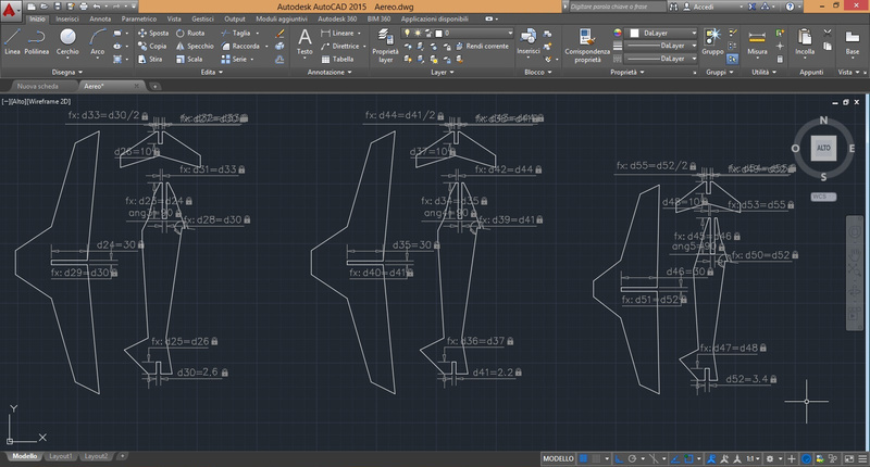
Besides Geometric constraints, in AutoCAD you can also insert Dimensional constraints. They control the size and proportion of a design (distances between objects, points on objects, angles between objects etc.). As described in Autodesk documentation, if you change the value of a dimensional constraint, all the constraints on the object are evaluated, and the objects that are affected are updated automatically.
I used linear constraints to fix the thickness of the joints and to parametrize their length. As you can see, I set the distance d1 = 2.6 mm (thickness of the material plus kerf). Then, I added the constraint to all the joints on the horizontal stabilizer, the fuselage and the wings.
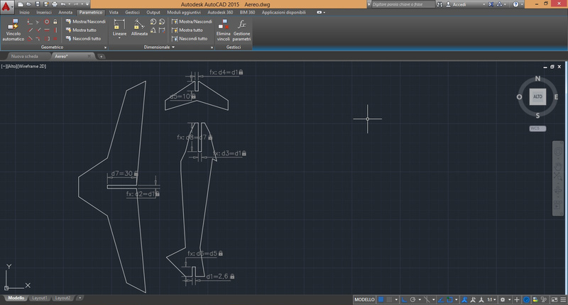
Similarly to FreeCAD (see what I did during week 2), I also added some constraints defined as math functions of other values.

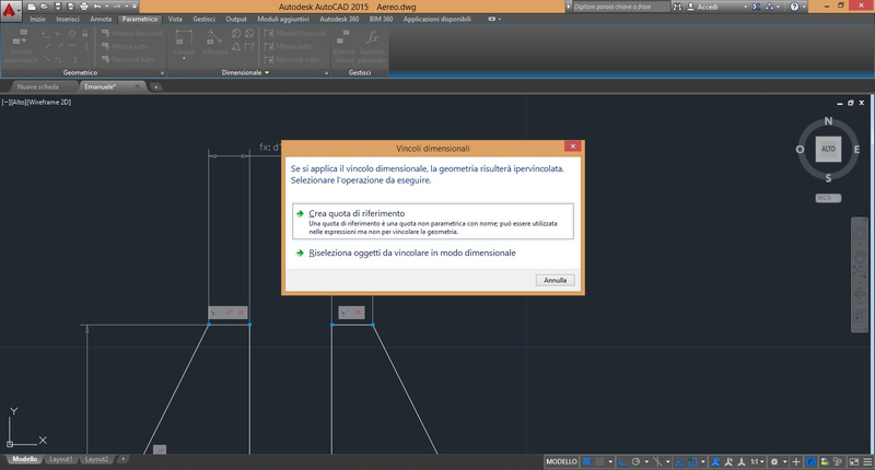
Keep in mind that is quite easy to mess up the design and over-constrain it if you add both Geometric and Dimensional constraints. Luckly, AutoCAD identify the overload of constraints and warns you that. In this case, I tried to add a dimensional equality constraint to the two segment of the cockpit. However, as you remember, I previously set a geometric constraint on these two segments and the program complained.
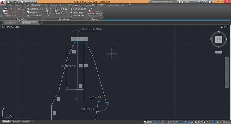
I added a constraint on the angle of the spike used for the elastic. This way the angle will always be 90 degrees. However, the shape opened and I had to closed again the profile using the Coincident constraint on the two points.
To check the correctness of the constraints, I created two copies of my design. In the second airplane I lowered the thickness of the joints. The, I scaled down the third design to .8 to check if all the constraints were working correctly. As expected, the design scaled nicely but the half-lap joints kept the original thickness.
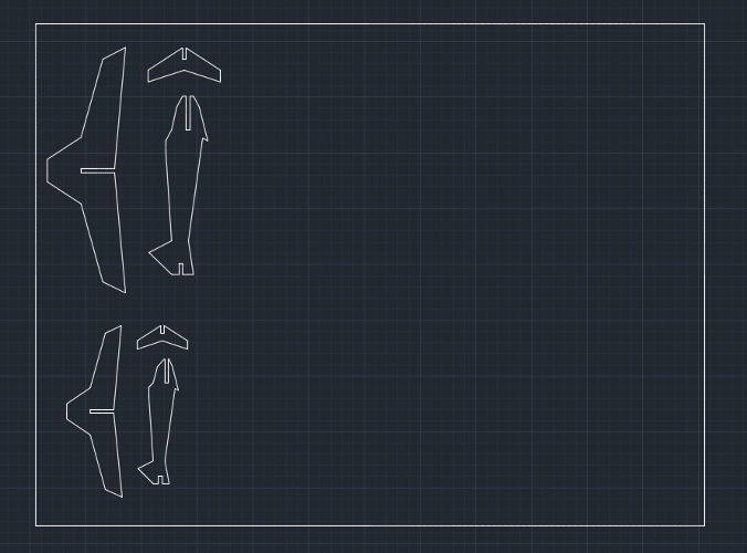
At this point, I copied the first and the third airplane to a new design, I reduced again the second airplane up to 70% of the original, and I put both model on the same file ready to be cut.
The material I used for the model is cardboard (thickness: 3 mm)
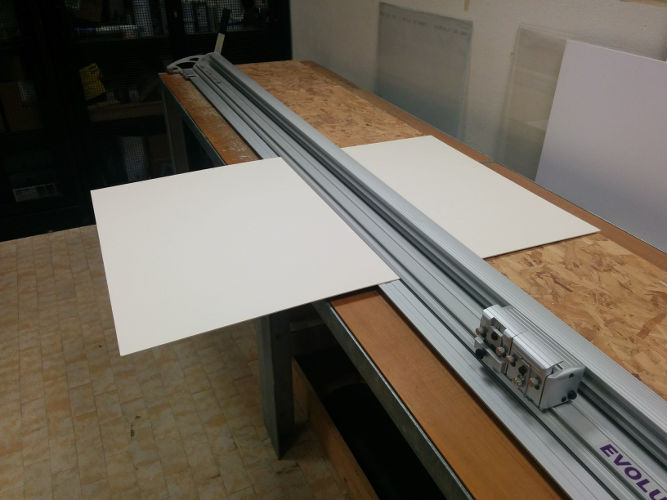
I put the 700x500 mm cardboard sheet into the laser cutter - a SEI Eureka CO2 machine
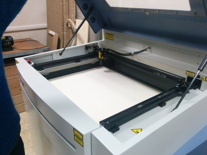
The ICARO proprietary software accepts .dxf files - I exported the cut file to dxf, imported it into ICARO, and set up the cut parameters:
- Laser working mode:
- frequency modulation
- energy (continuos) mode
- Heading speed: 170 cm/min
- Heading acceleration: 10 m/s^2
- Laser cut setup:
- power 90%
- frequency 10 KHz
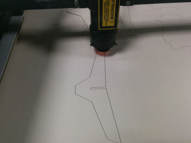
As you can see in the video, the process is really fast: it took less than 2 minutes to cut both airplane models.
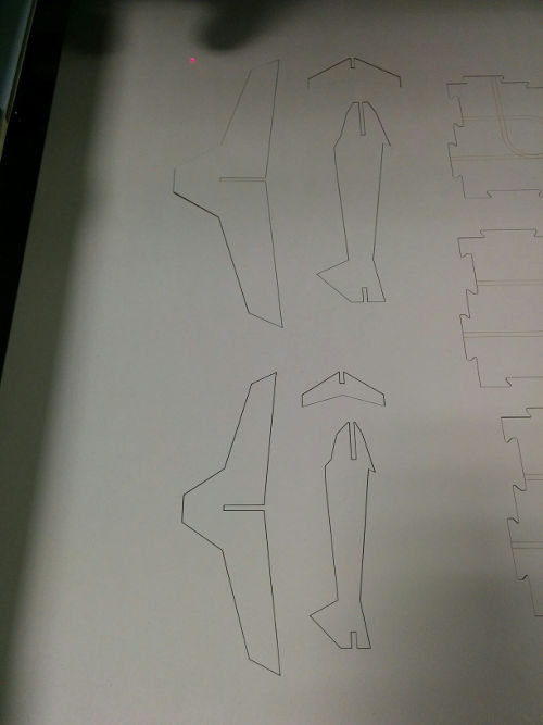
The result is quite nice: the shapes are clearly visible and can easily removed from the cardboard sheet.
The pieces are on the table ready to be assembled - can you spot which belongs to the scaled one? ;-)
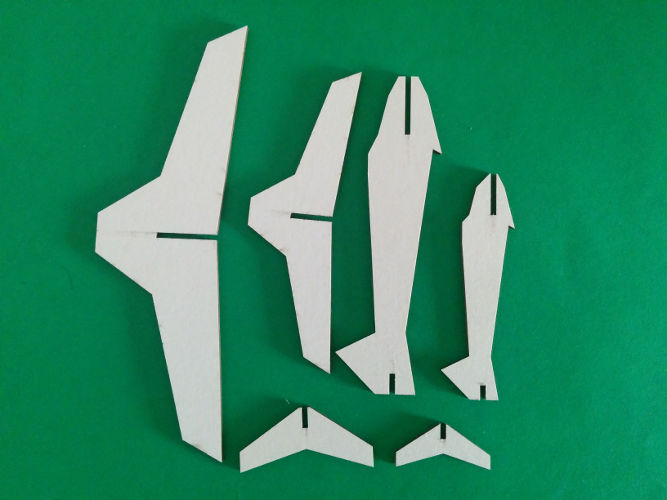
Ladies and Gentleman may I have your attention please, we are now ready for takeoff, so please fasten your seatbelts. Thank you!
Download zone - List of files
- vinyl1.jpg and vinyl1.jpg - Raster (JPG) and Vector (SVG) penguin design
- airplane.dwg - Parametric Airplane DWG AutoCad file
- airplane.dxf - DXF file for laser cutter