Test the design rules for your printer(s) (group project)
Design and 3D print an object (small, few cm) that could not be made subtractively
3D scan an object (and optionally print it)
Test the design rules for your printer(s) (group project) you can find
HERE
This test I worked with Guillermo Guerra, you can find all the files in the final of the link page.
Learning outcomes:
1)Identify the advantages and limitations of 3D printing and scanning technology
Printing
The 3d print permiss me make prototypes in short times, also you can personalize your own designs, this tecnologie permis lower prices. You can design your own prototype or send a file to print in another place.
I can not find limitations because the 3D printers are evolving so fast, and i can not see limitations. I am thinking it because I do not have much experience with 3D printers. It is the firs time for me with 3D printers.
Scanned an object
I learned that we cannot make hard positions, because if you are going to print it, you have to think in that, if we make a position in the air you probably you will need soports to print it.
also we have to take off glasses, watches or things than afect the sensor. it depends of your sensor but you have to take in account.
2)Apply design methods and production processes to show your understanding.
Scanning
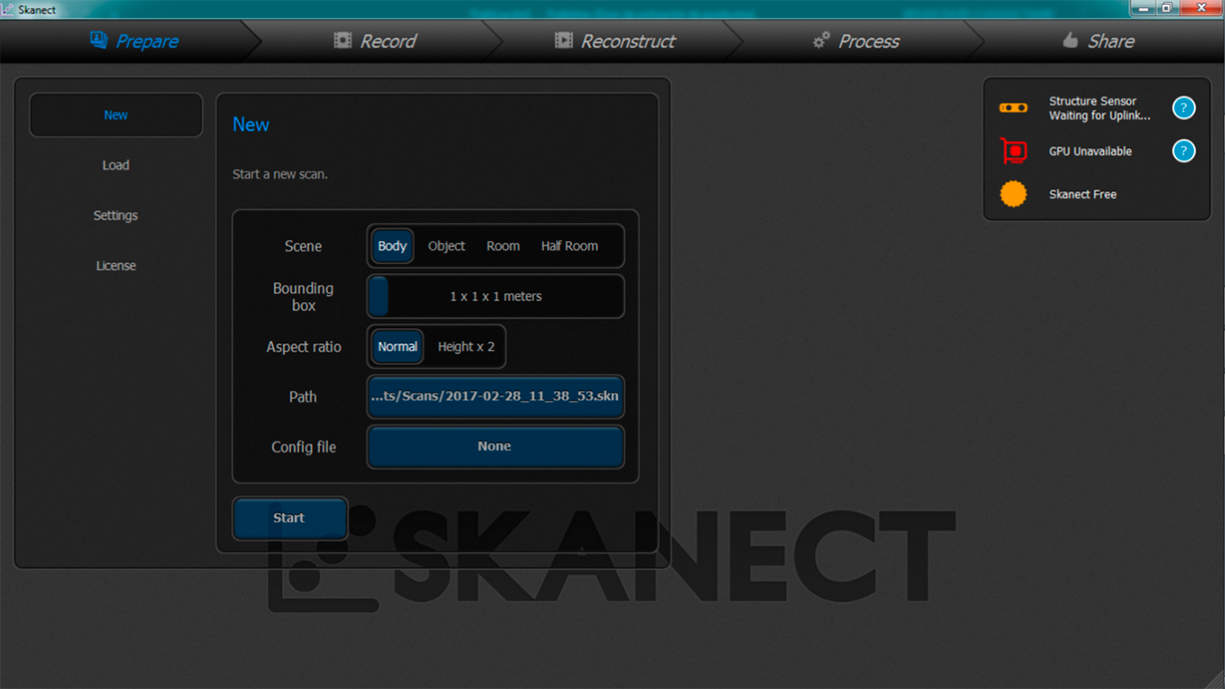
The first step is scan.
The software is Skanect, and the sensor is Kinect.
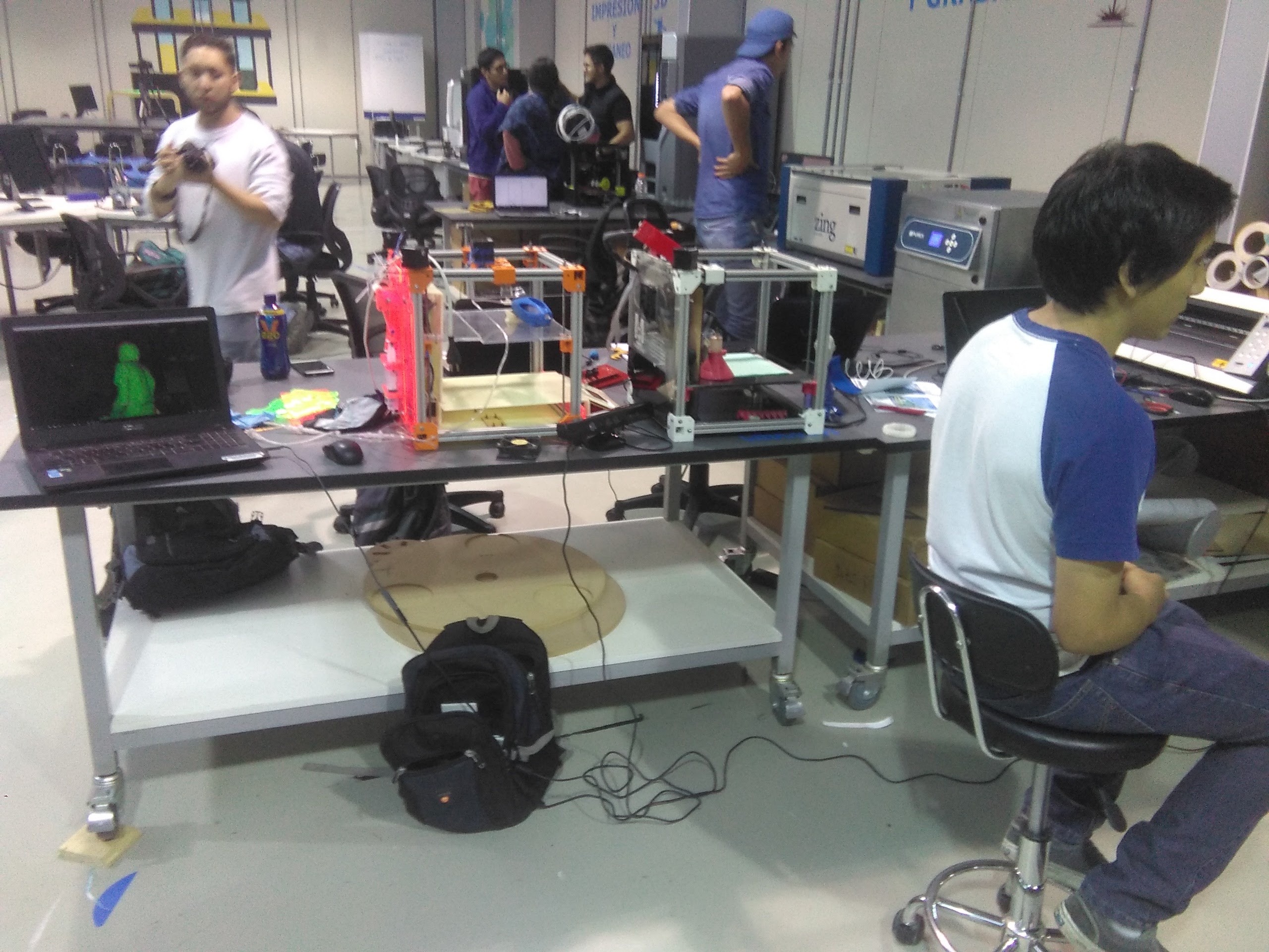
If you use the kinect sensor, it is recommended take care with the distance of the object to scan, when the image in the software skanect
is green it is good, when the color is red it is bad, move the object or the sensor.
the process in the skanect is really simple, you just have to follow the steps in the upper part of the window, just select the options, then you have to prerss the "record" button to start.
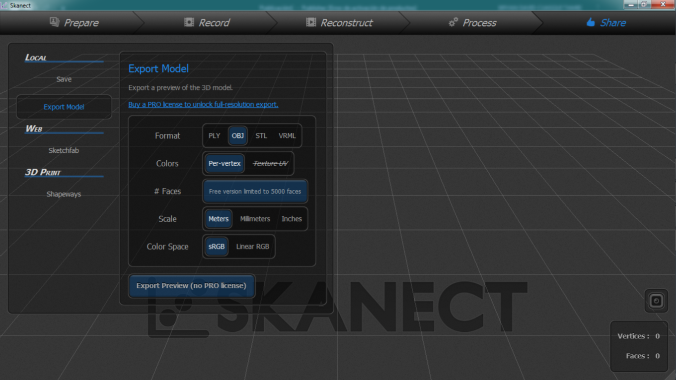
When you finish the "record" of your object save the file, we save the file in .obj format
In this picture you can see to my co worker of fab academy Juan Guerra, I show this picture because I could not take a photo of me.
2) Outlined problems and how you fixed them
The next step is fix the file.
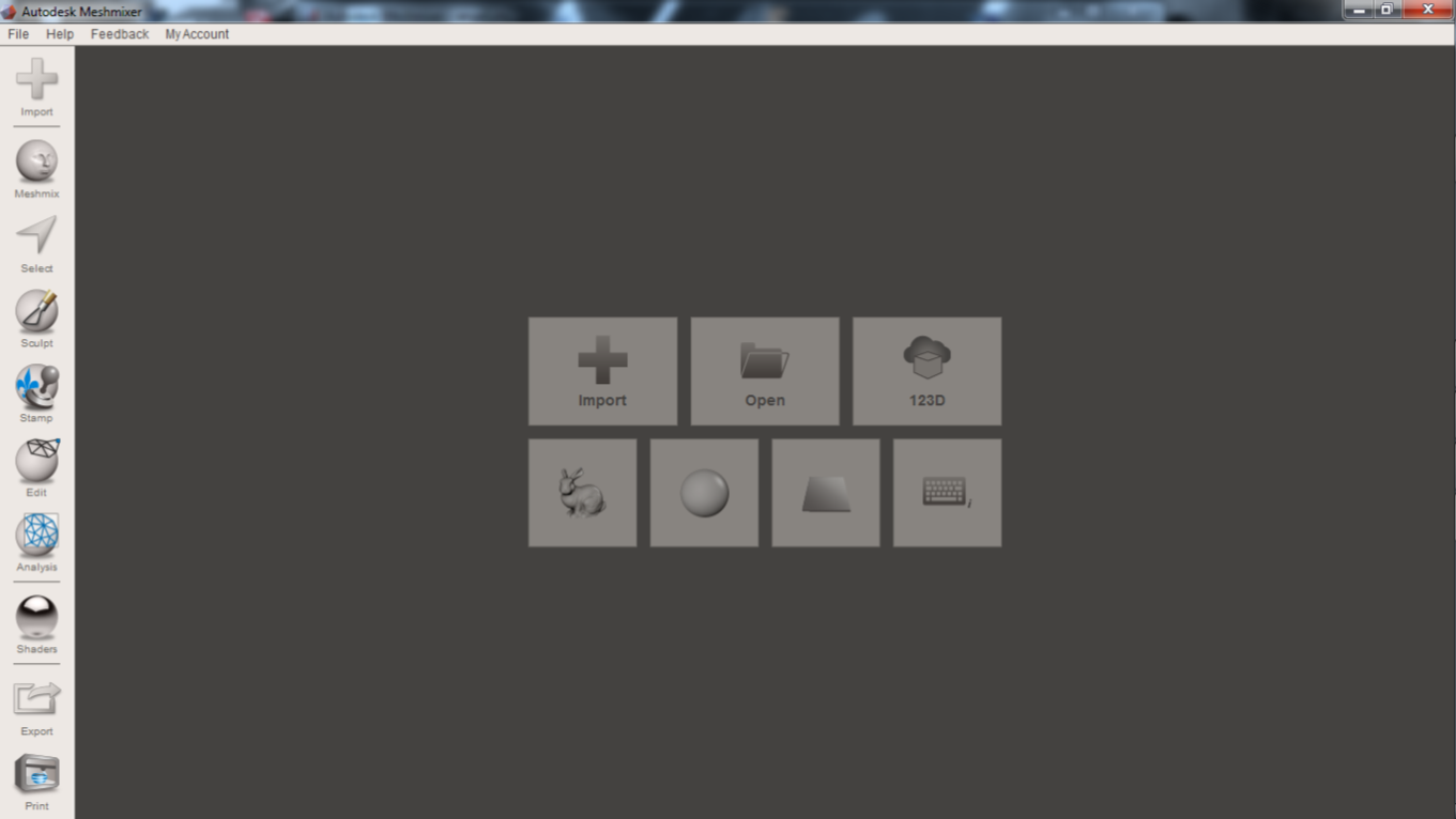
We use the Meshmixer software to fix the file.
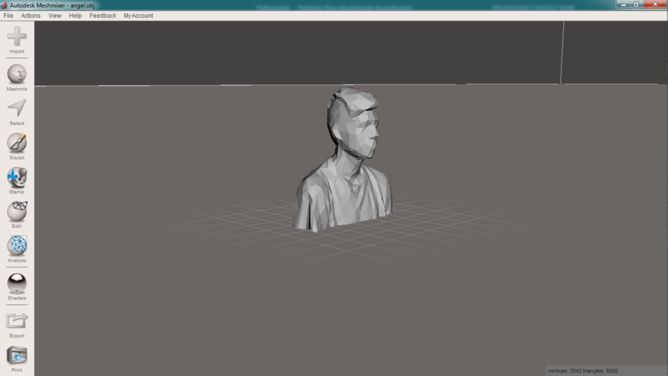
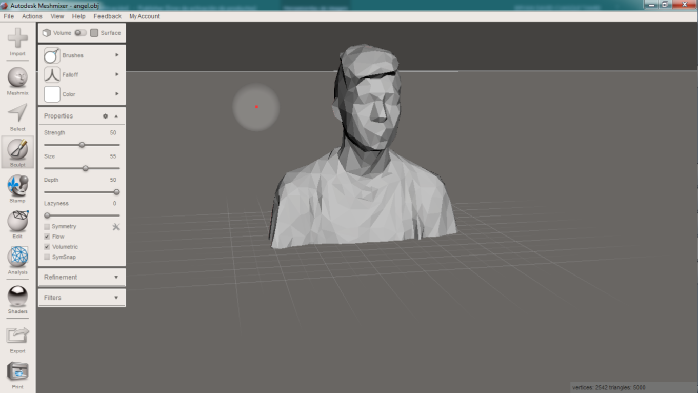
upload the file then we saved in skanect. When the file is open you can see the file than you scan. Look at the following image.
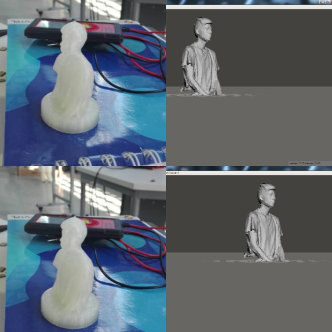
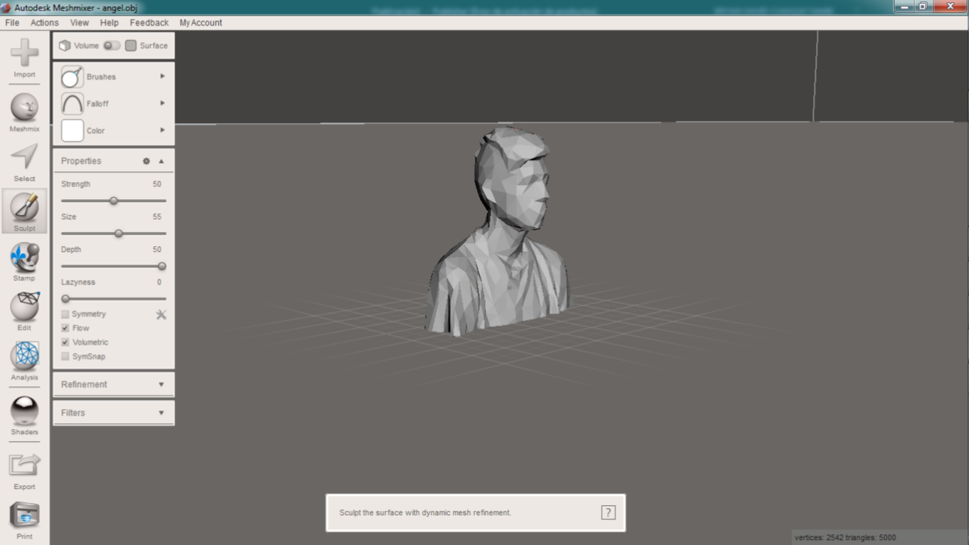
When I opened the file, I could see the image can be improved, to make it I used the tools of Meshmixer.
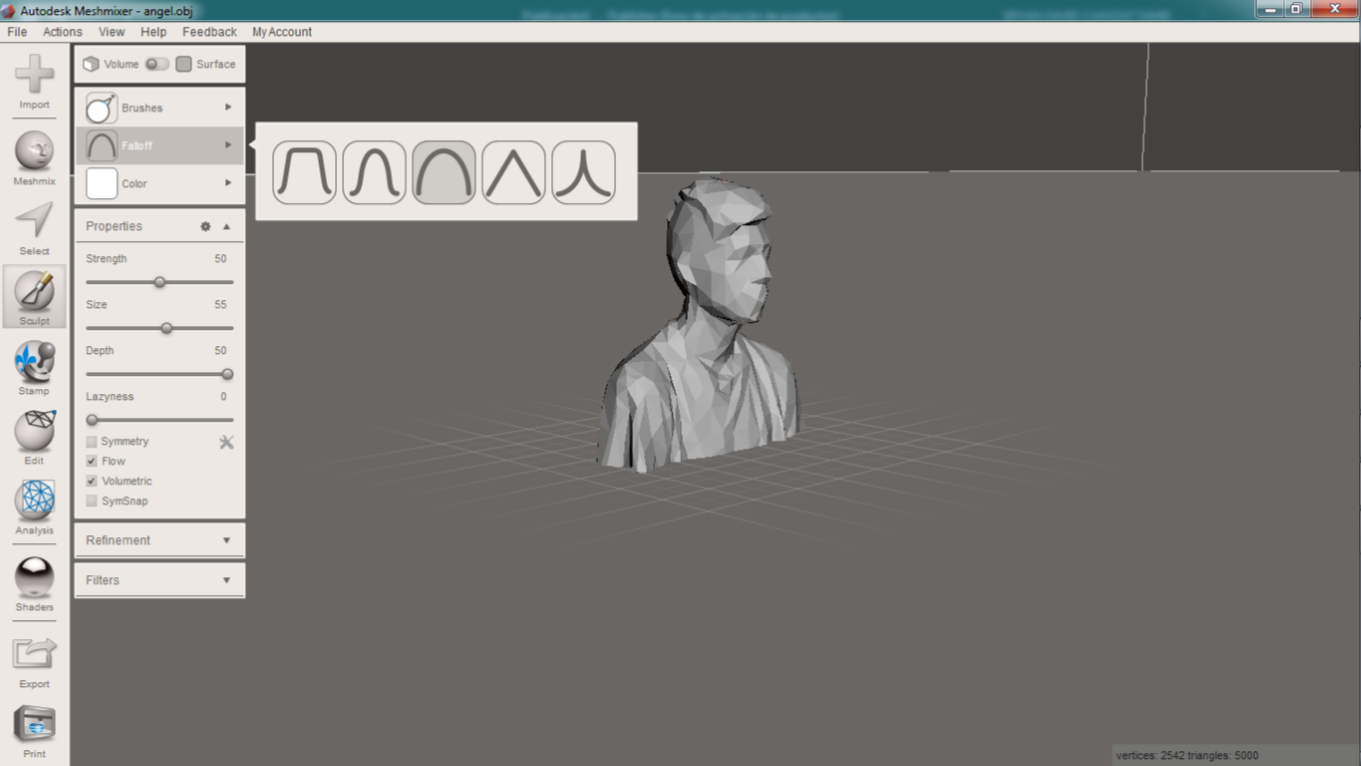
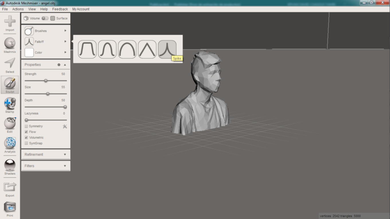
We can use tools like "Sculpt", and select some options, I used "Fall Off" and then select "spike" to apply in the file.
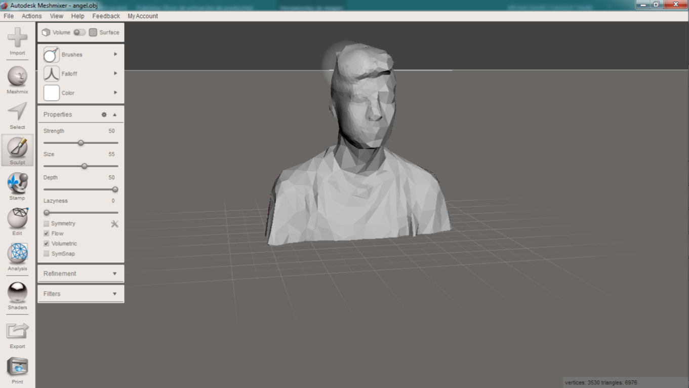
In the next image, you can see the difference to apply "spike" in the file. And the final outcome.
if you apply this tool the image gets smooth.
3D Printing
3) Described what you learned by testing the 3D printers
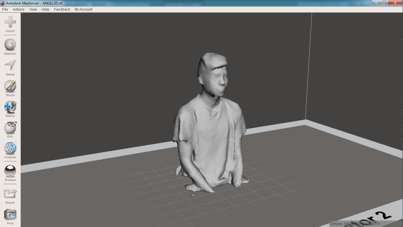
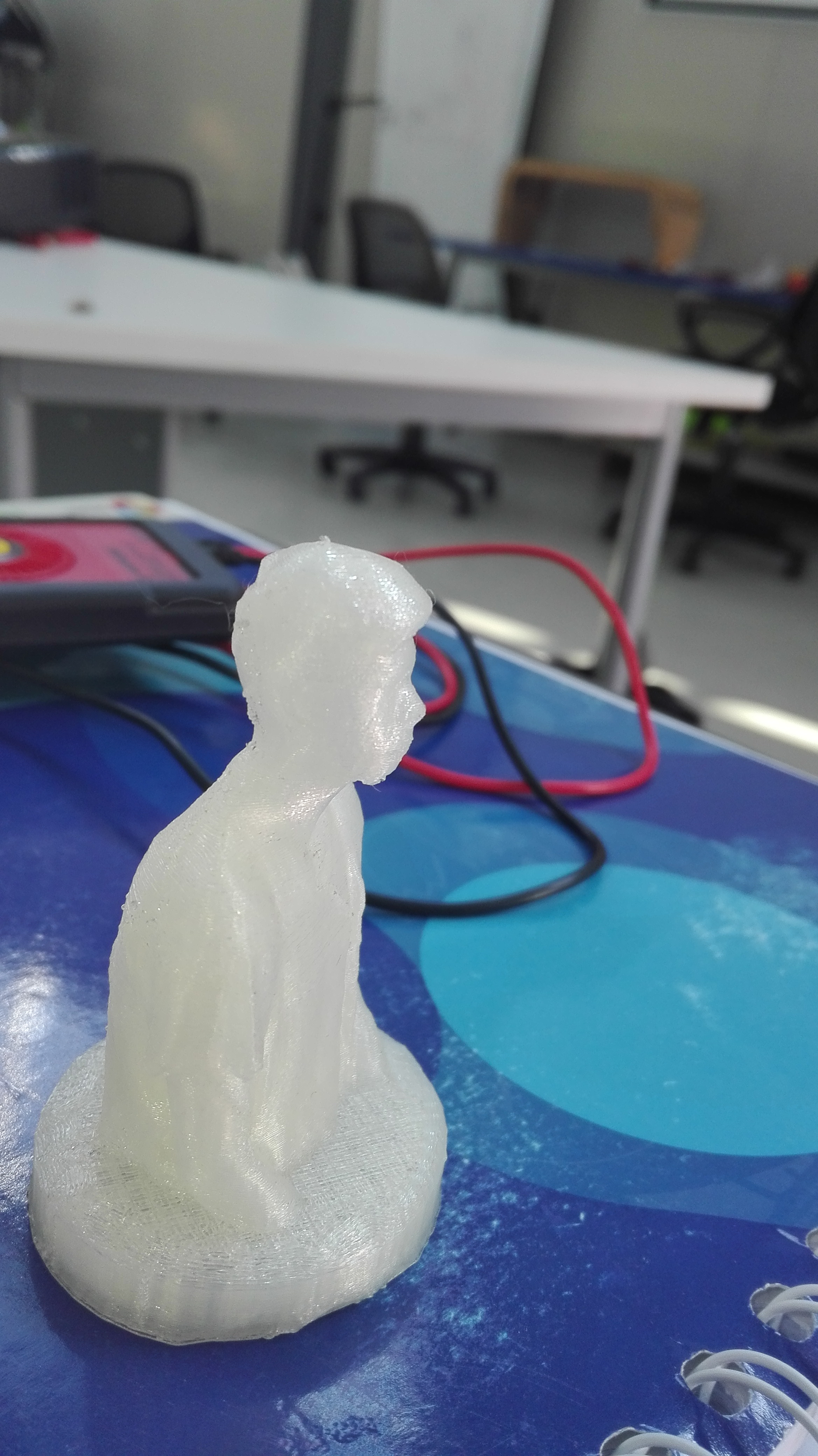
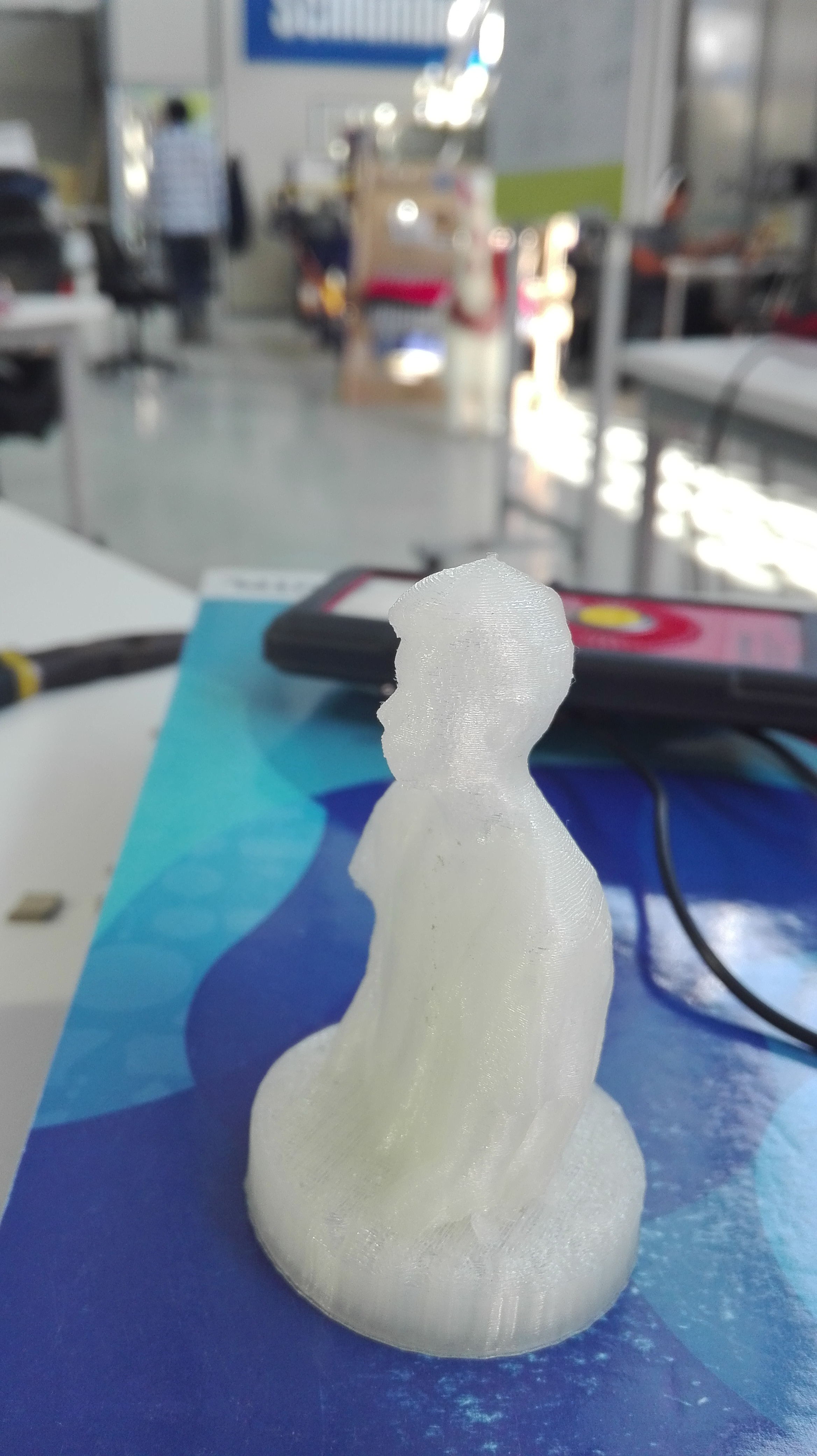
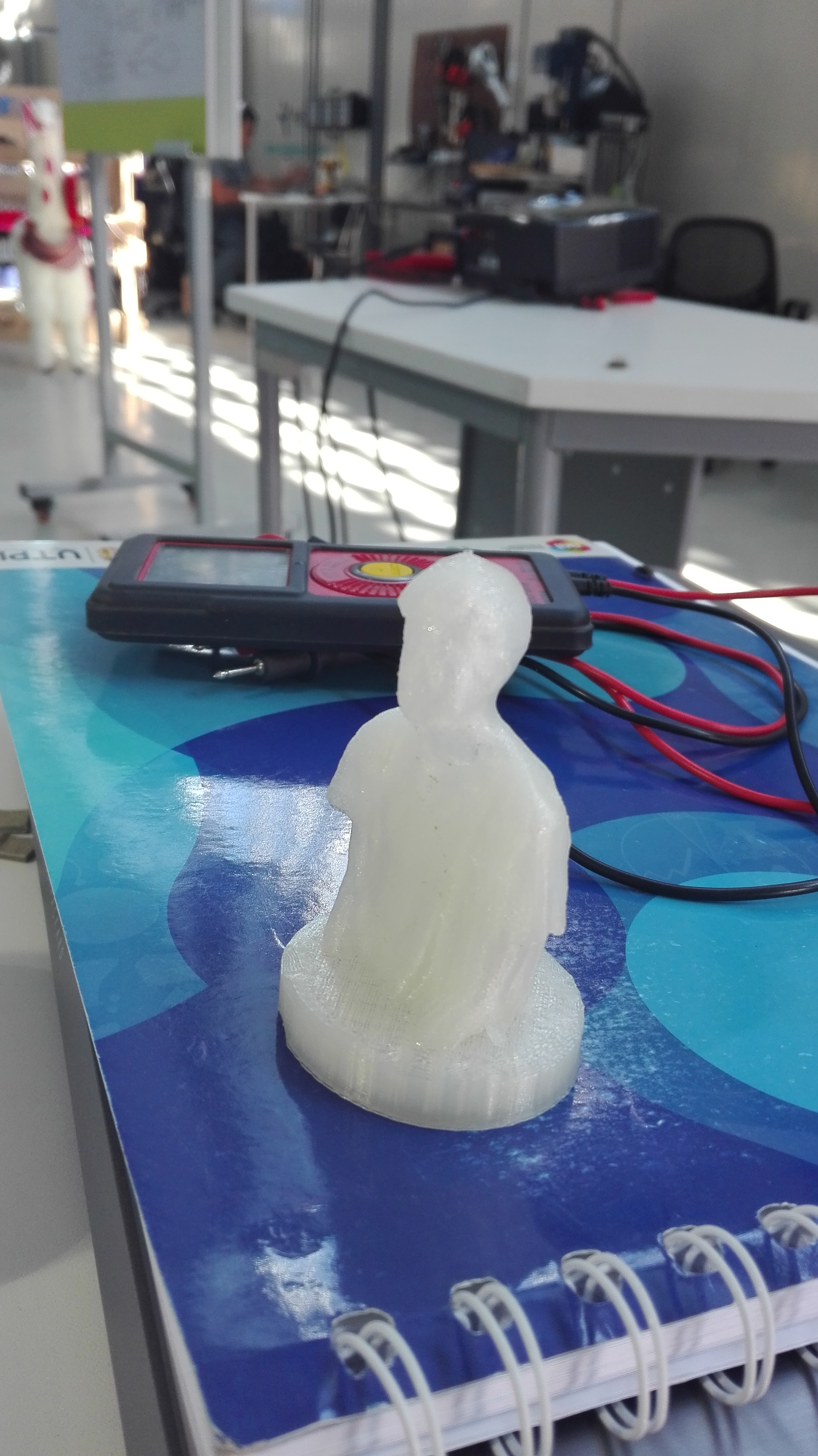
You can see the previous pictures, it is me. I decided to print this file. down is the outcome. I used Meshmixer to edit and create my .stl file to print.
it is really easy because you justly have to see in the windows on meshmixer the export option.
I printed this file with 20% of density, this file finished around 2 hours.
You can find this files in the final of this page, STL and OBJ files.
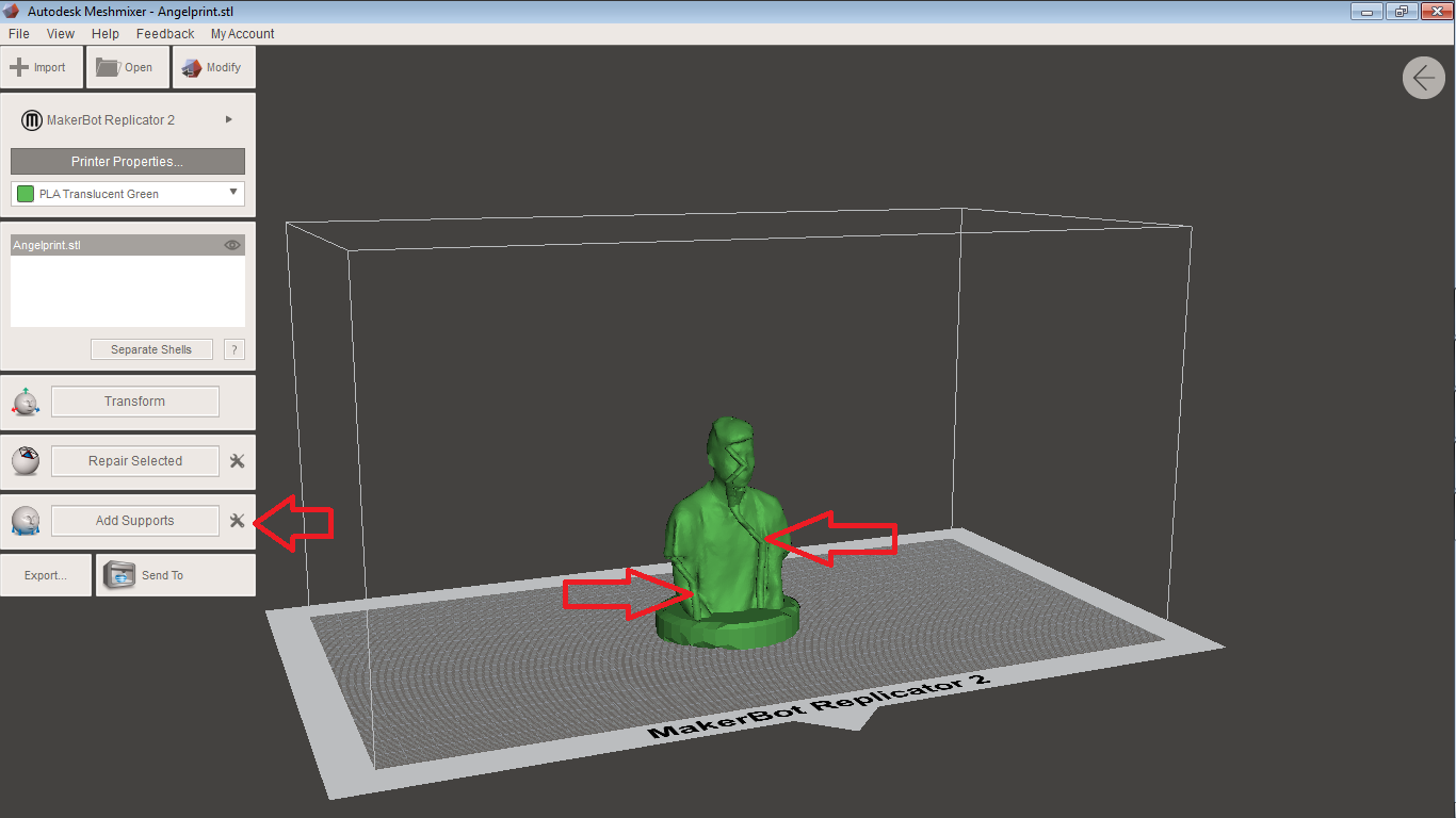
In this picture you can see the scan file but this design has supports, to add supports you can see in the left palette a option to add supports, you just have to press the button add supports and this software add the necessary supports.
Is really important take in count the kind of material than you are using.
The temperature is around 180C to 220C with PLA, 230C to 250C with ABS, the velocity to print and the density on the piece. The time needed to print is based on this parametres.
4) Shown how you designed and made your object and explained why it could not be made subtractively
3D Desing
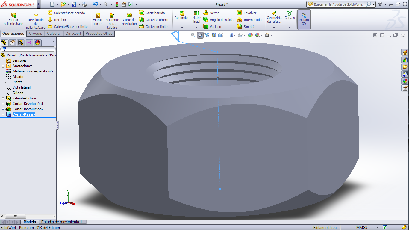
I made a 3D design, this design has a Internal thread, it is a nut.
I used Solidworks to made it.
I like Solidworks to make this kind of things. This is a greatsoftware to work in 3D models.
I think it is not a easy software, you have to learn and practice a lot because in this software you can create a lot of 3D models.
it can not be subtractive for the shape of your internal thread.
You have to learn to use the different planes, also you can extrude or intrude just with easy tools.
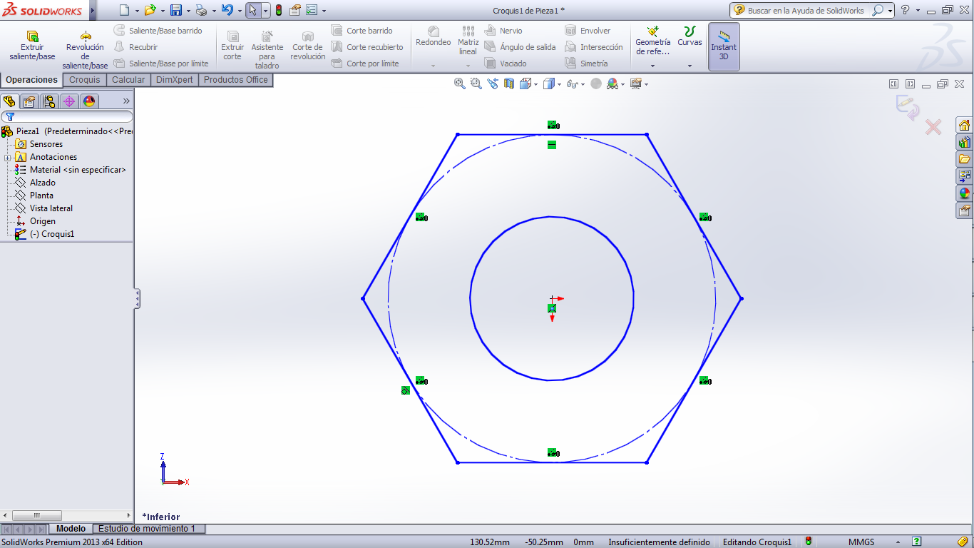
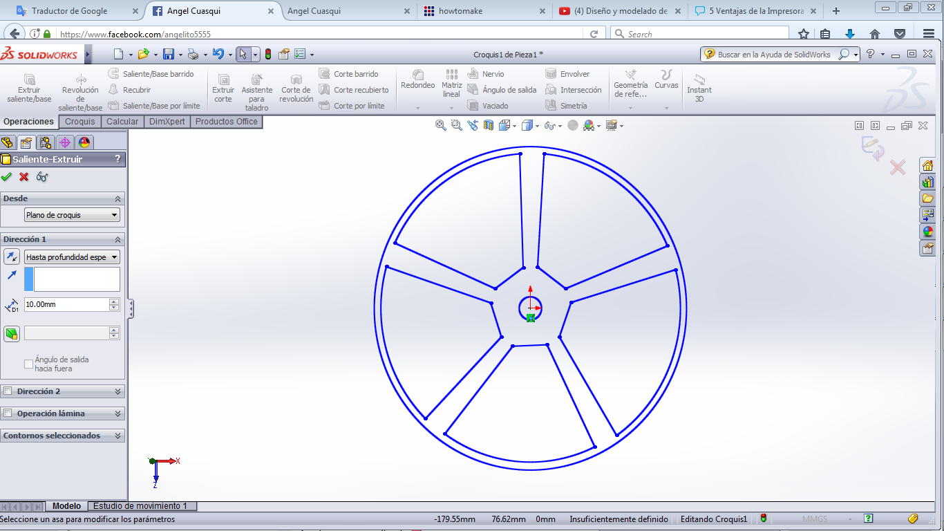
You can see the first image is a 2D plane, I just extrude with the tool Extrude to get a 3D model.
I like this software because you can make a lot of things so fast, you can see a spiral in the next pictures.
You can make it just with a tool and changing parameters, it is easy to me.
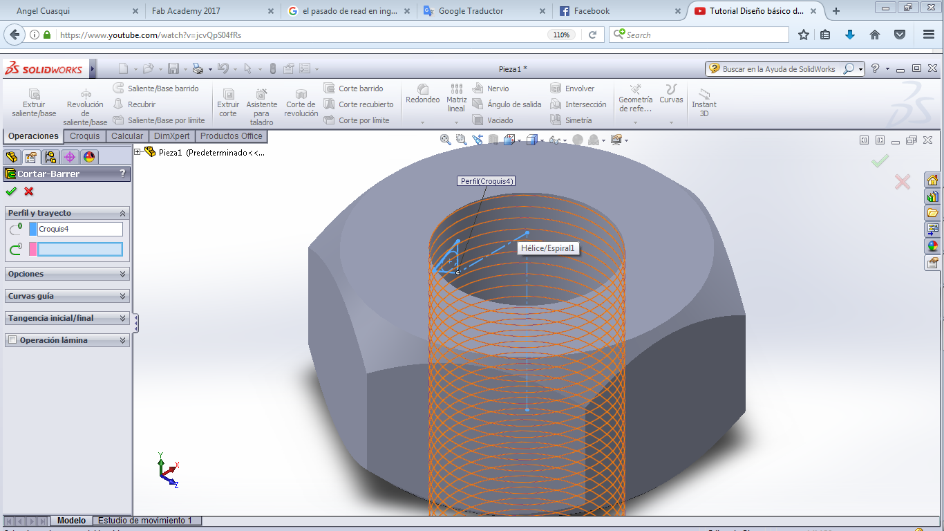
I used the spiral to get a Internal thread.
I just needed the spiral and a triangle to make this Internal thread on my nut.
Also i followed a tutorial and you can see the video here.
You can donwload this file in the final of this page.
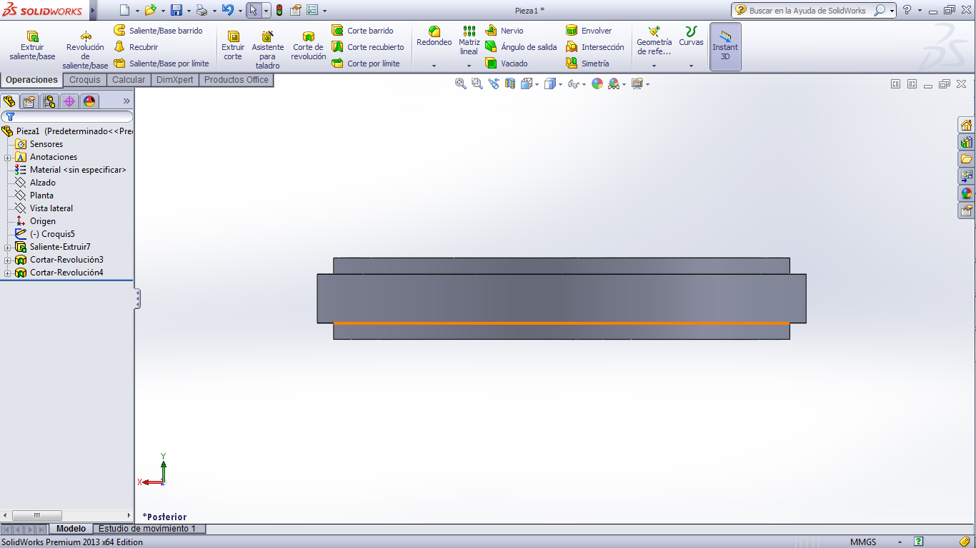
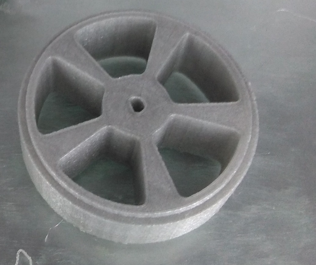
I designed a ring to my final project, I need a wheel and I am going to cover this ring with a composite silicone.
I used Solidworks to make it.
I created a circle on my plane, then I added rims,
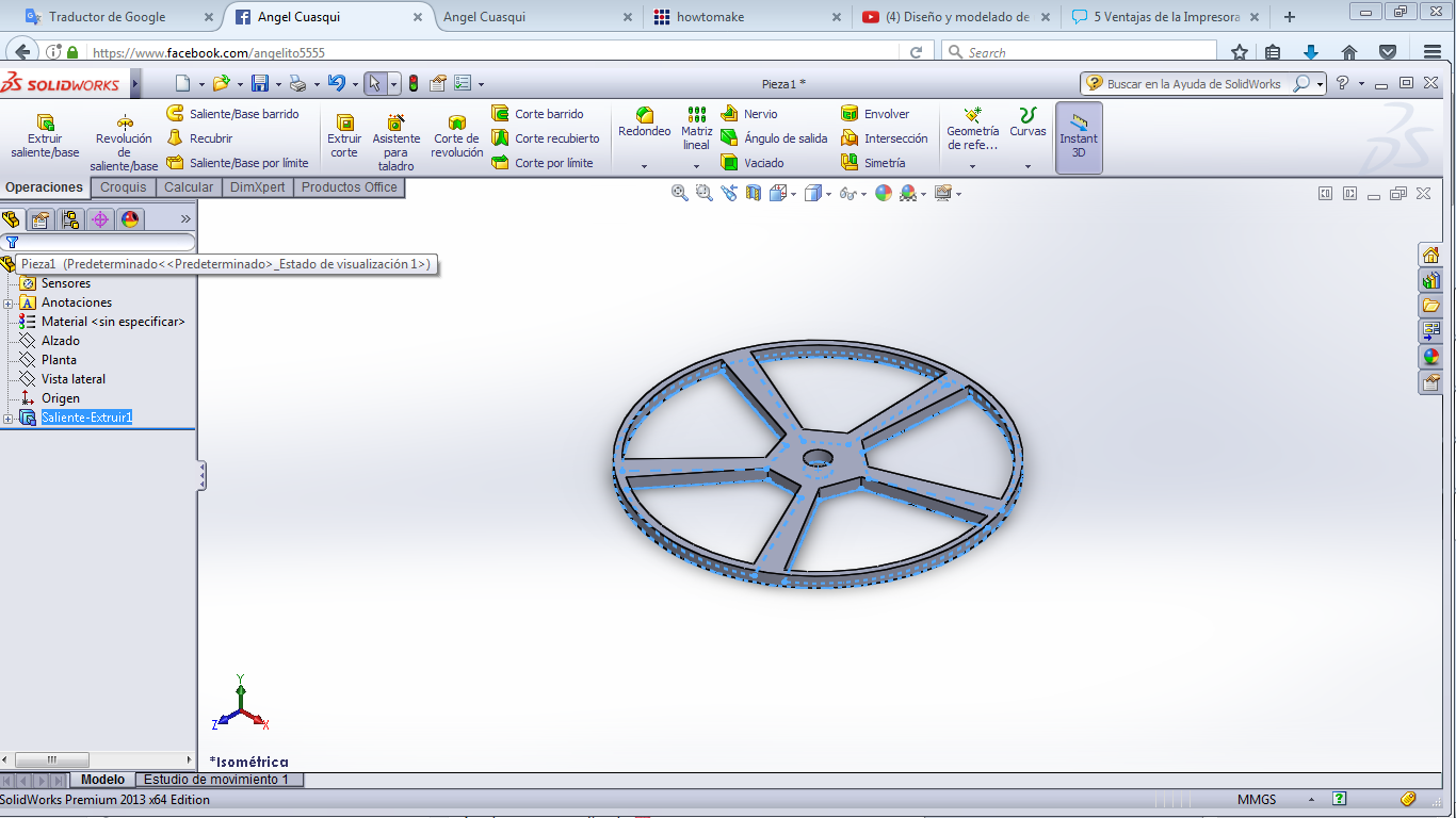
I extruded the ring a size of 25mm
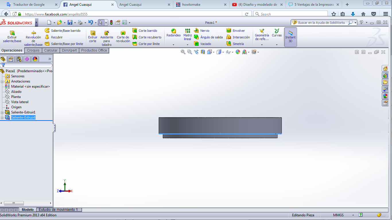
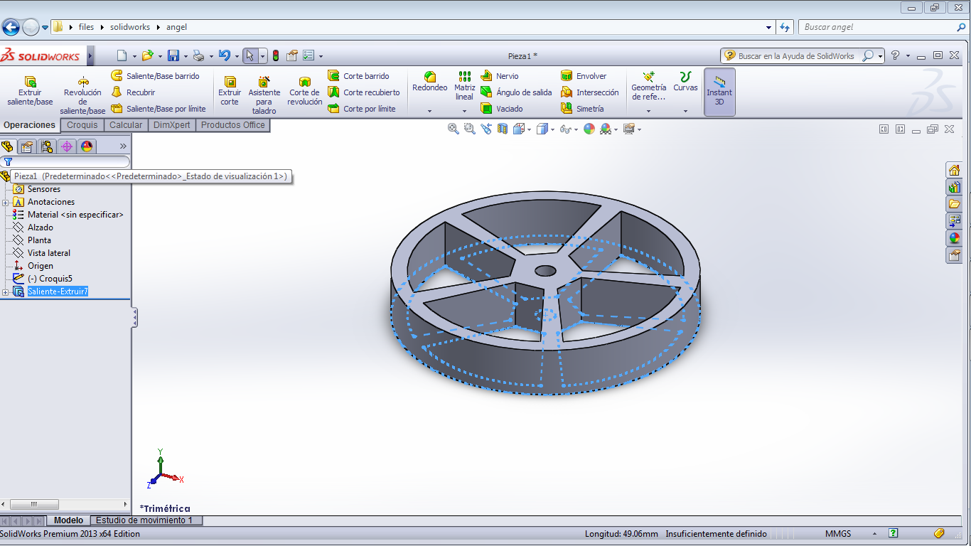
then I used "Revolution cut" tool because to cover the composite matrial.
The idea with this cut is hold on the silicone with the ring.
I think than this design can not be substracted because it has some terraces, if you try to substract this design is really possible get fails like hollows.
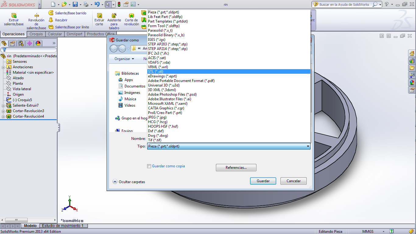
I exported a STL file to print.
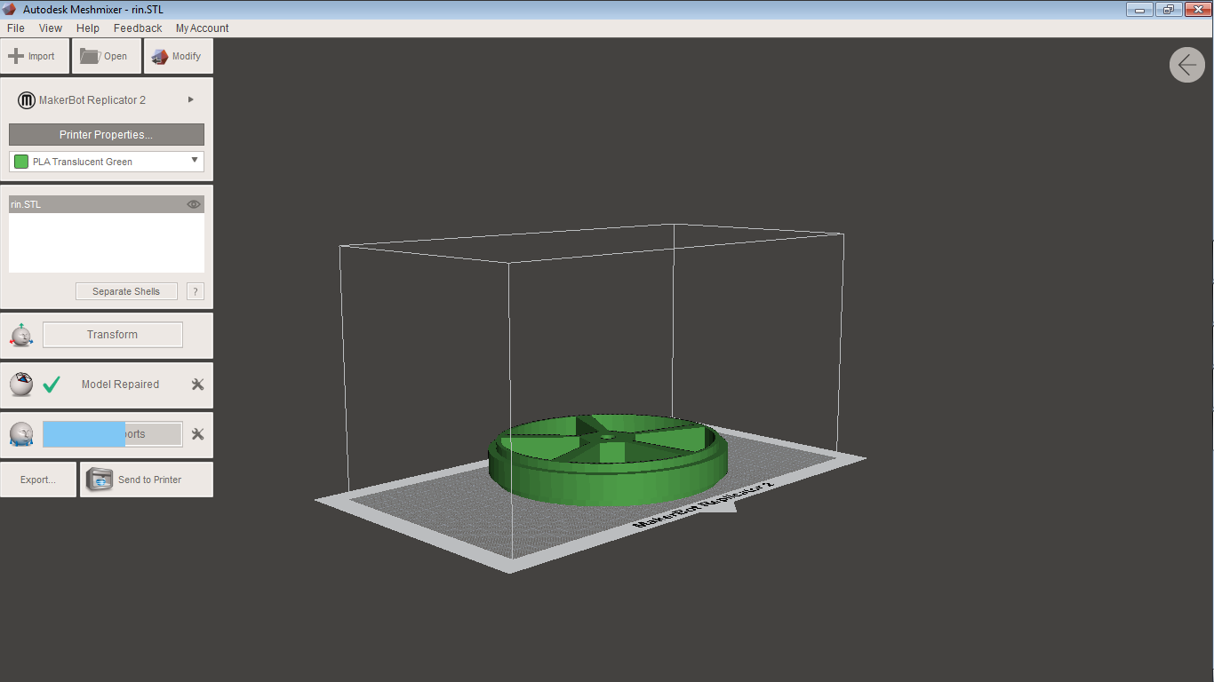
I opened the stl file in Meshmixer, then I exported the file to print.
This ring has a configuration of 40% of density, the time to print was around 3 - 4 hours. it is because the desity is high.
Included ‘hero shot’ photos of the scan and the final object
you can find all the files stl and original desing in the final of this page