Make an in-circuit programmer by milling the PCB (program it, so that you can use it to program your board in Electronics Design week, and in other weeks)
Optionally, trying other processes.
Learning outcomes:
1)Describe the process of milling, stuffing, de-bugging and programming
2)Demonstrate correct workflows and identify areas for improvement if required
Creating files to cut
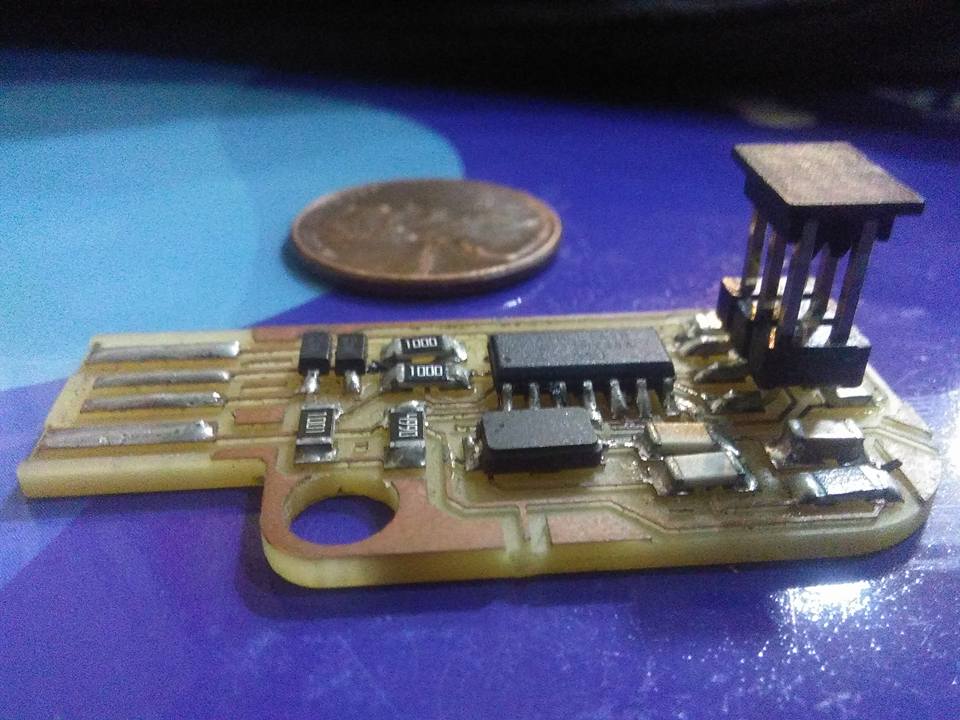
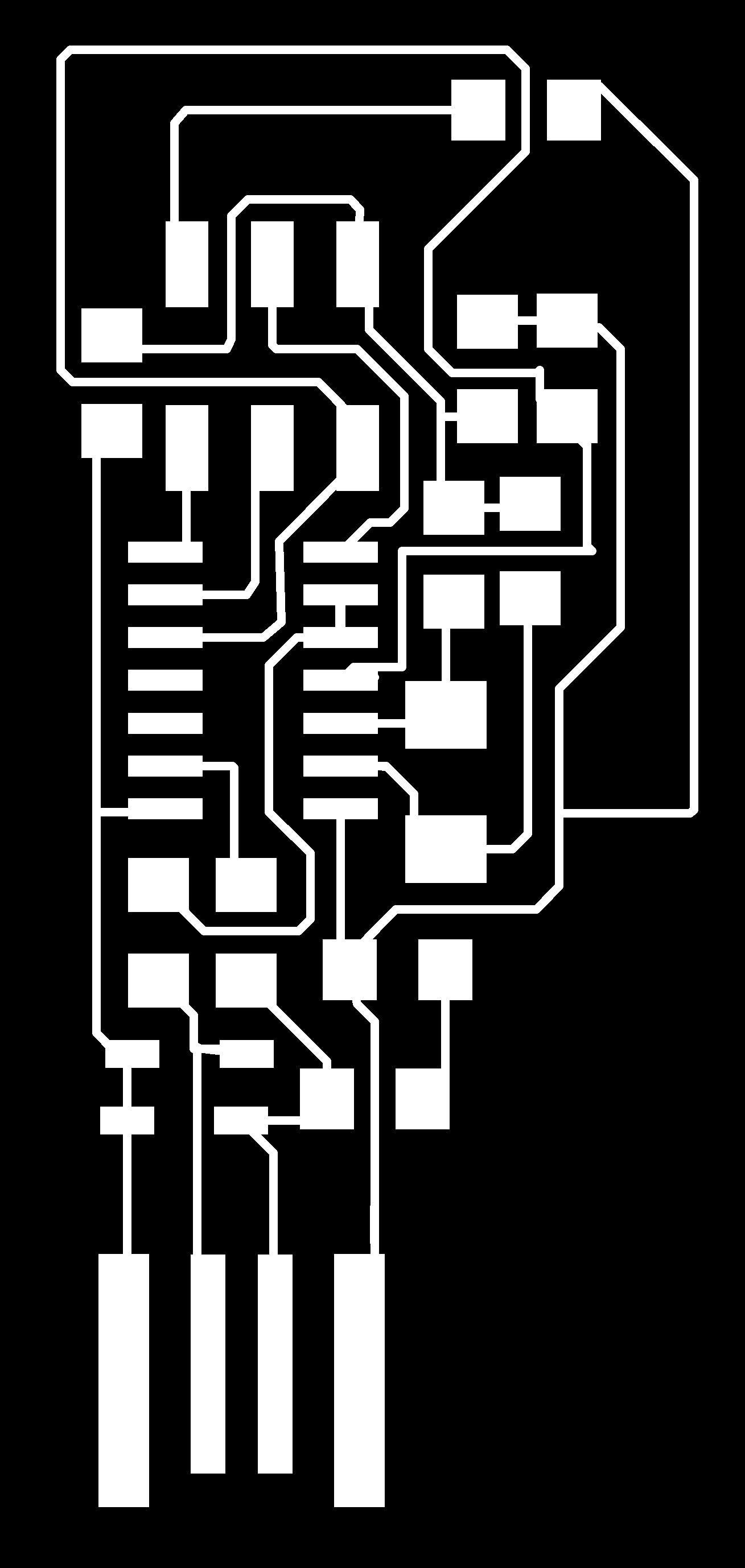
Select the PCB design, Two files, the first is traces (left image), the second is to cut (right image).
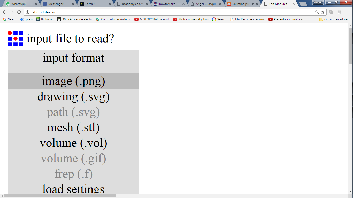
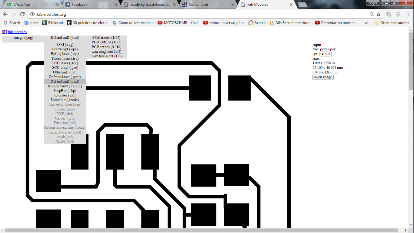
Open http://fabmodules.org/ , select the input format image (.png)(left image), upload the image, then select Roland mill (.mil),
after PCB traces (1/64) to do traces, and (1/32) to cut (right image).
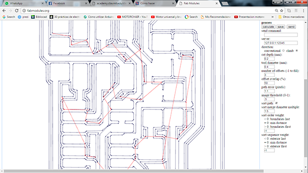
To do traces, we have to edit the next properties and then press the button calculate.
Cut Deep: 0.2
Tool diameter: 0.4
Number of offset: 3
You can see the properties in the next image:
If you finish to configure the file, press the button save and the file download automatically to your computer.
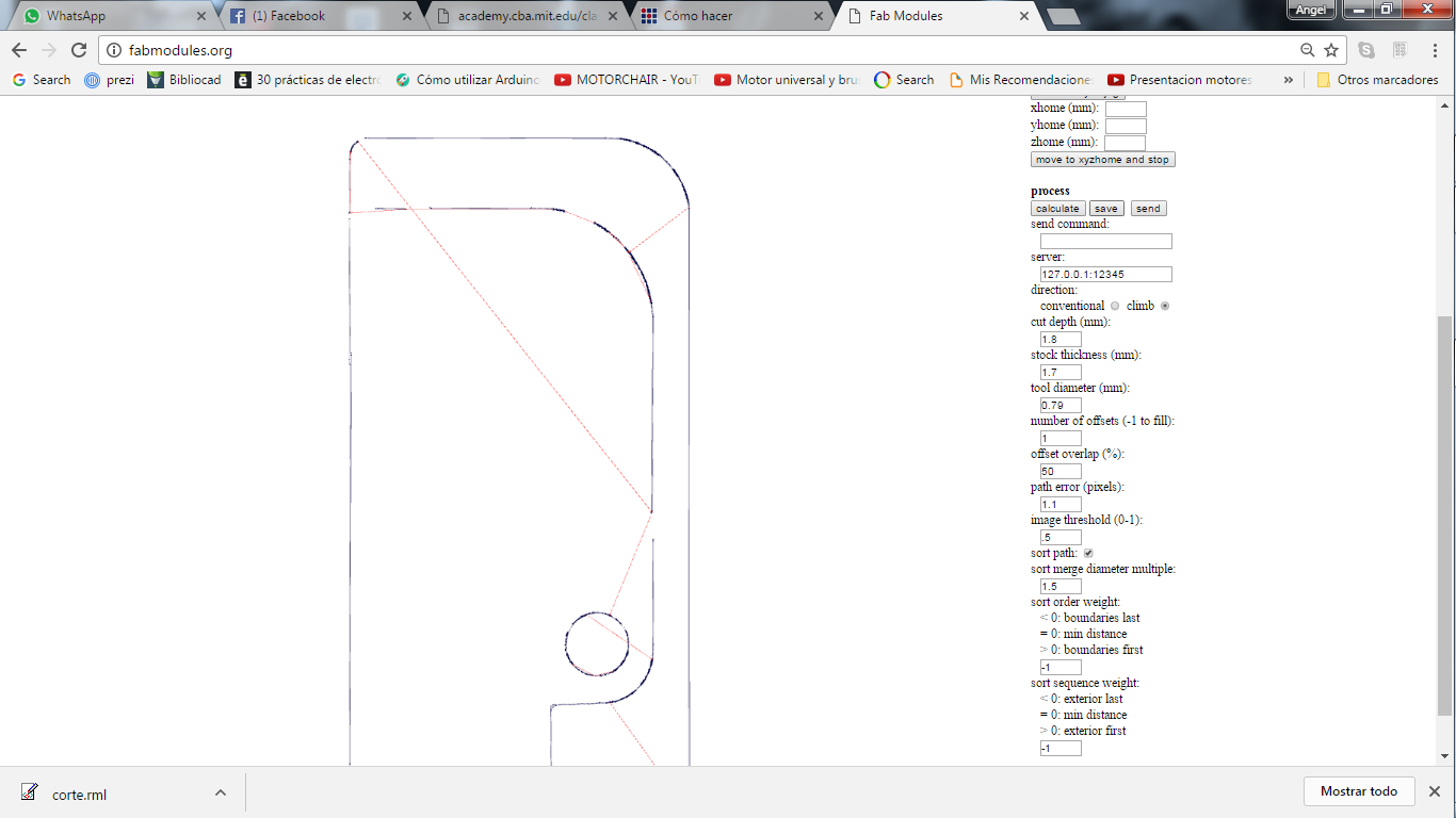
To create the cut file, we just have to change the option Cut Deep, this configuration depends of the material we work, we use Cut Deep:1.8
because we material is 1.7mill, then we press Calculate, if the file is ok, press save to download the new file.
Cut
Steps
1) Turn on the machine
2) Open Vpanel software
Choose the machine model.
3) Select the option Set base point
We take a test of move
4) Select the option Attach/Detach
Tool selection
Replace 1
With the replace option, we can take the milling machine, the number in front is the tool position
5) Place the plate on the workplace and adhere it to not move.
6) Select the option "Set base point"
Set base point
Set (XY Origin Home)
Set(Y Origin)
In the next step you have to be really carefully and take account that the sensor is connected and on the correct position, then press "Set detection"
Set Z Origin (Set detection)
Then, Verify the velocity
Spindle rotation speed (10000)RPM
When everything is ready, save the information, push the option apply.
7) Select the option cut
Erase every files in the window. then, upload your files and press the option output.
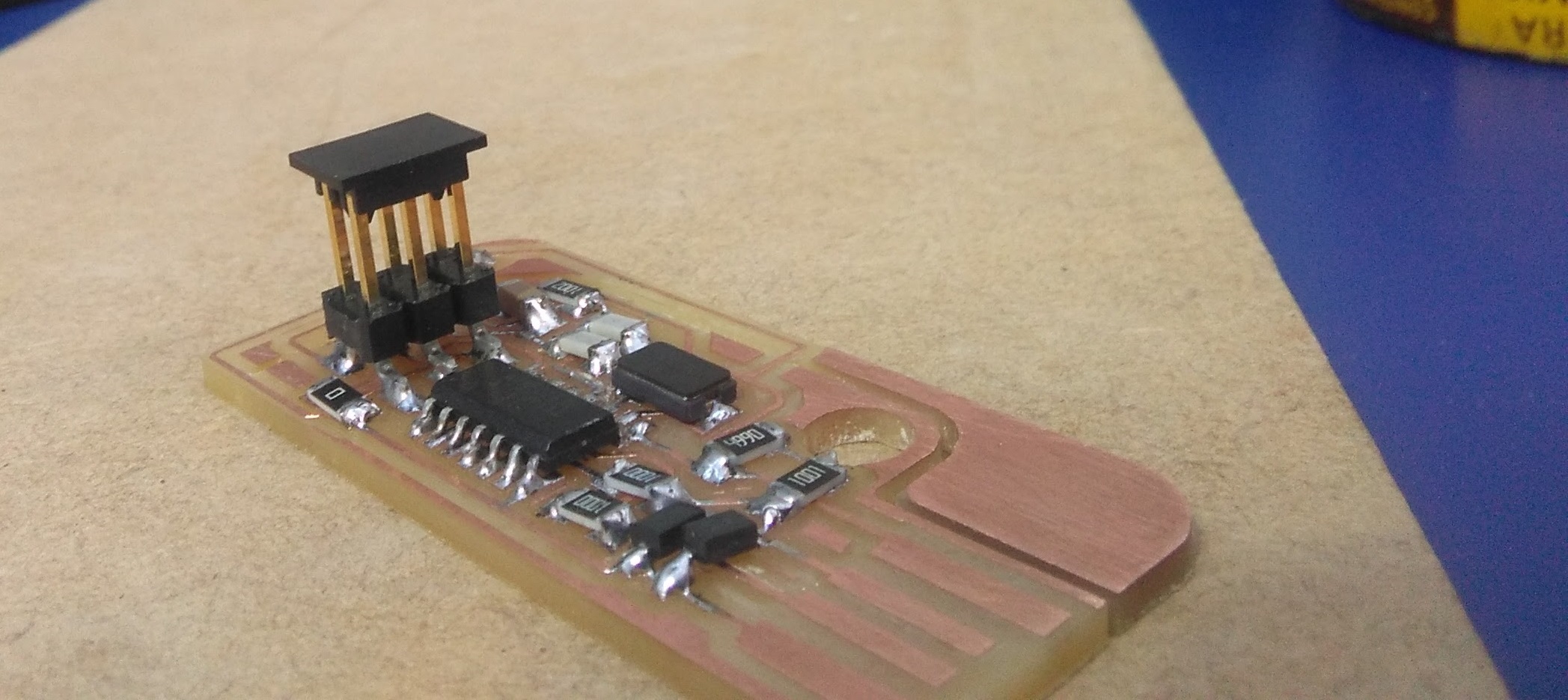
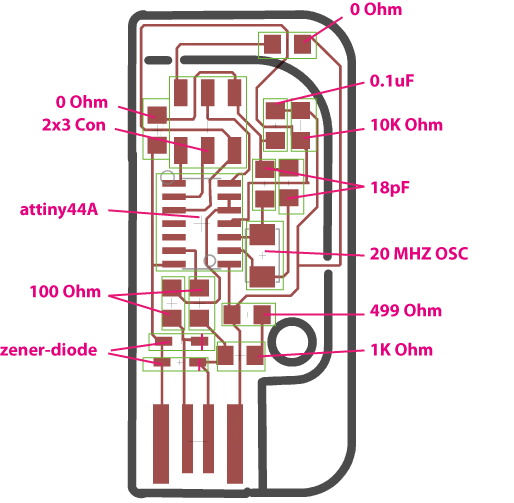
Welding the electronic components
When the PCB is ready you have to solder the electronic components, you need the assembly picture to make it and the BOM, you can see it down.
I did not have problems to soldering, I add a little of tin with the soldering tool in the PCB, then i add the component.
Recommendation: When the machine do not move with the software,you have to restart with the remote control pressing the button Clear,
take care because the machine drops the tool, it can break the milling.
Programming FabISP
We had an instructor to program the FabISP. and we made a video calling, you can see the video here.
the instructor was Carlos Moreno FabAcademy 2016.
I program the file of BRIAN, you can find all the information here, the information is really complete.
BRIAN "Building the FabTinyISP"
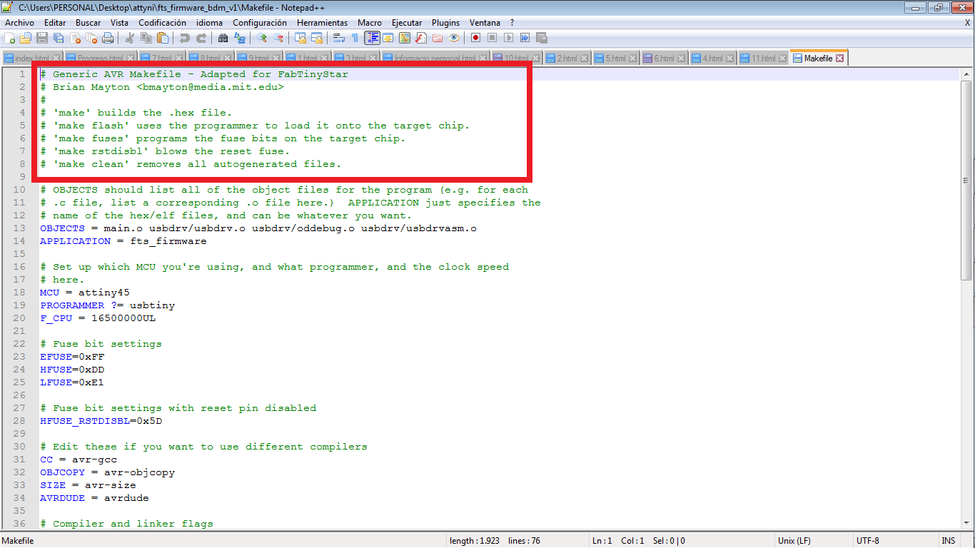
All than do you need is the firmware, I am going to let you the firmware down to you can download, all that you have to do is follow the steps in the make file, to make file is inside the folder firmware.
1) open the CMD window.
2) paste the direction of the folder of firmware
3) make clean
4) make hex
5) make fuses
6) make flash
All the steps were completed, the FabIsp programing is done.
The FabIsp worked perfectly
In this process we got to program our FabISP really good. thanks to Carlos Moreno to helps we.