Write an application that interfaces with an input and/or output device that you made, comparing as many tool options as possible.
Learning outcomes:
1)Interpret and implement design and programming protocols to create a Graphic User Interface (GUI).
Have you:
2)Described your process using words/images/screenshots
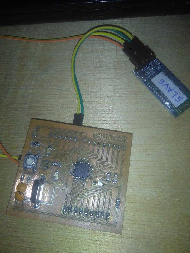
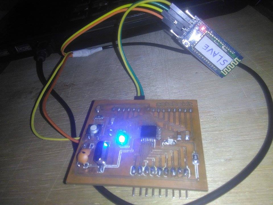
I decided to make a Android App with app Inventor, this Android app is going to turn on and turn off a led, I was reading about satshakit and I decide to make one. satshakit is a arduino board, satshakit is a project of Daniele Ingrassia, if you wat to learn about it
Here
I described the process of Satshakit a little better in the asignment of
input devices
, I made satshakit in that asingment.
I downloaded the files and machine the board,If you want to know how to mechanize a board, please review the electronic production assignment here.
3)Explained the the GUI that you made and how you did it
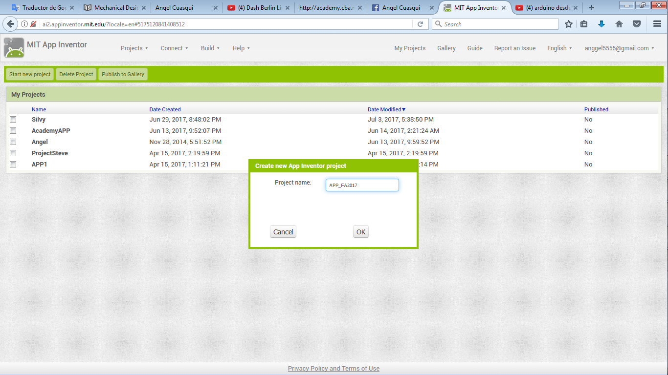
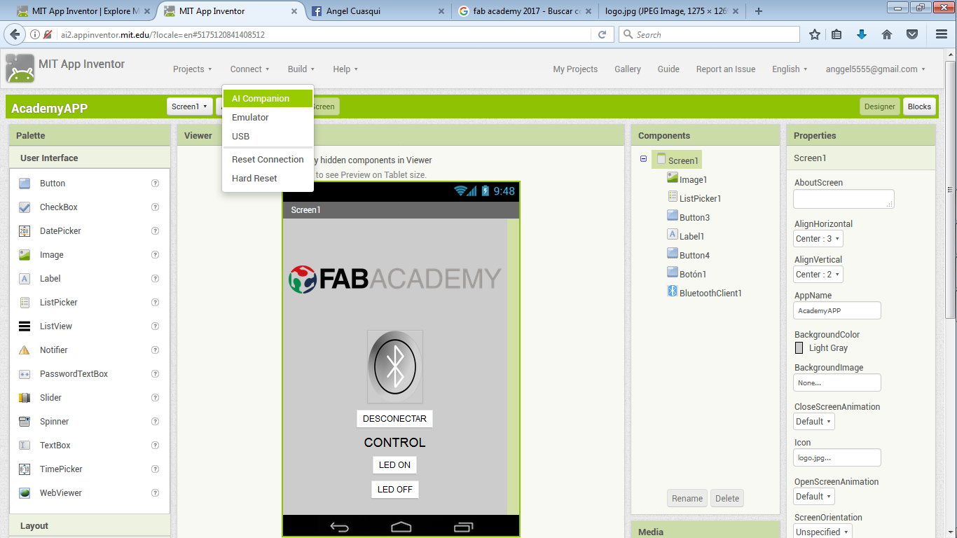
How to use MIT App Inventor, you have to crate a new project, and you have to write a name of your project.
Then it opens the project and you can see a window, in this window you have to add the components than you need.
You have on the left all the complements than you need.
In the middle you can see a rectangle, in this rectangle you have to add all the complements than you need, you justli have to drag the complement.
In the righ tool palette you can change the characteristis and modify the complement than you added.
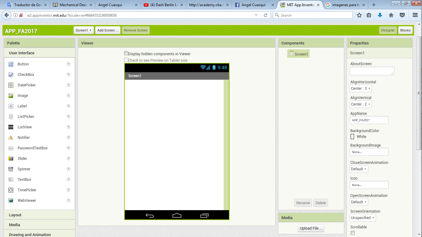
You can see on the right two buttons, designer and blocks.
Designer: it is a window to design your App, you can add buttons, image, sliders and so much more.
I think it is the visual design of your App.
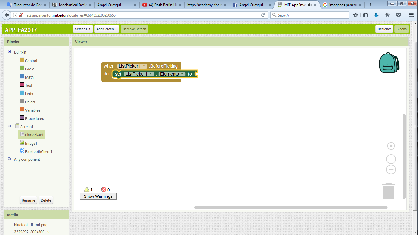
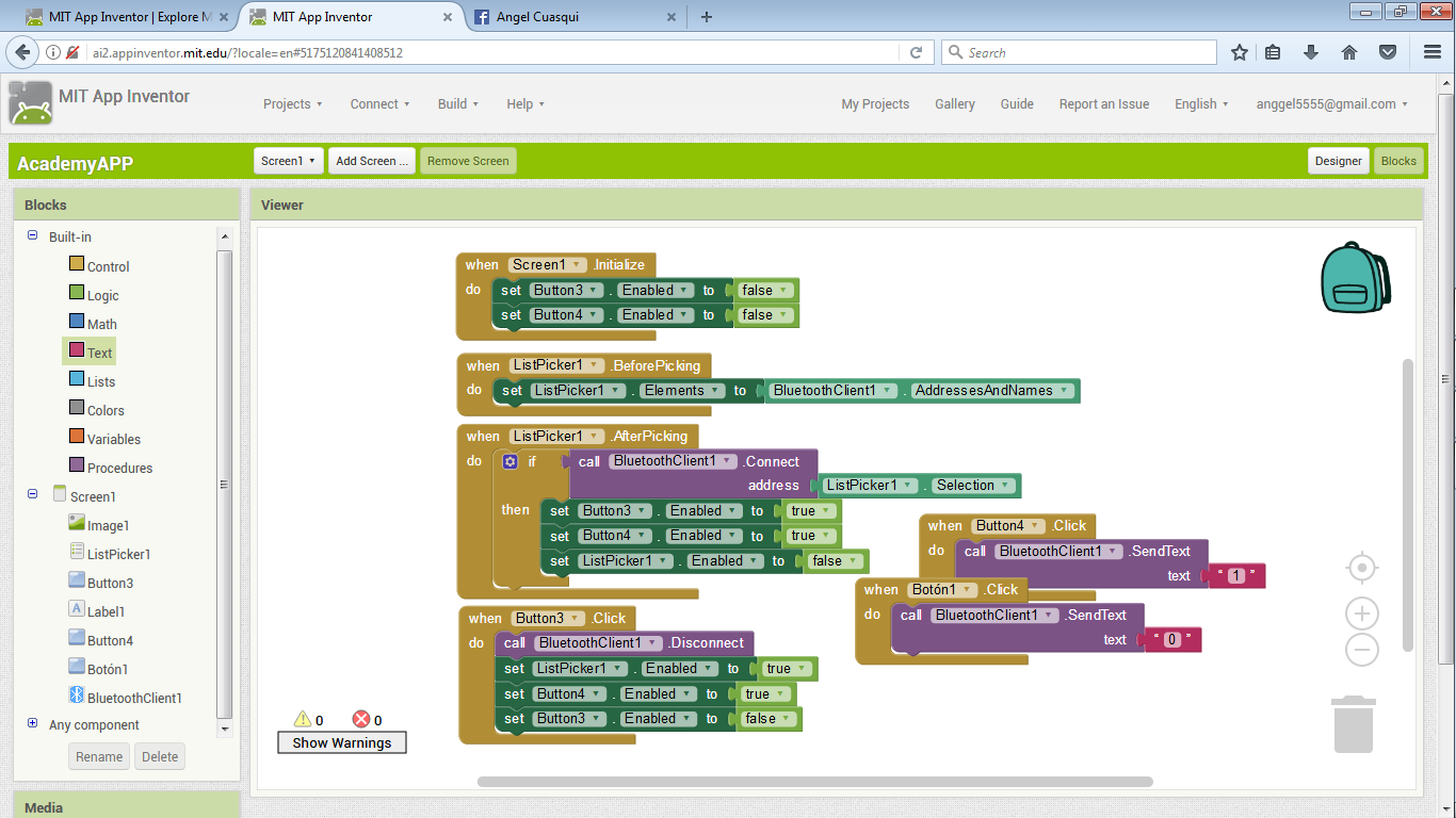
Blocks: it is the window to configurate or program the operation of yor App.
In this window you can configure the buttons, and all the program of your App.
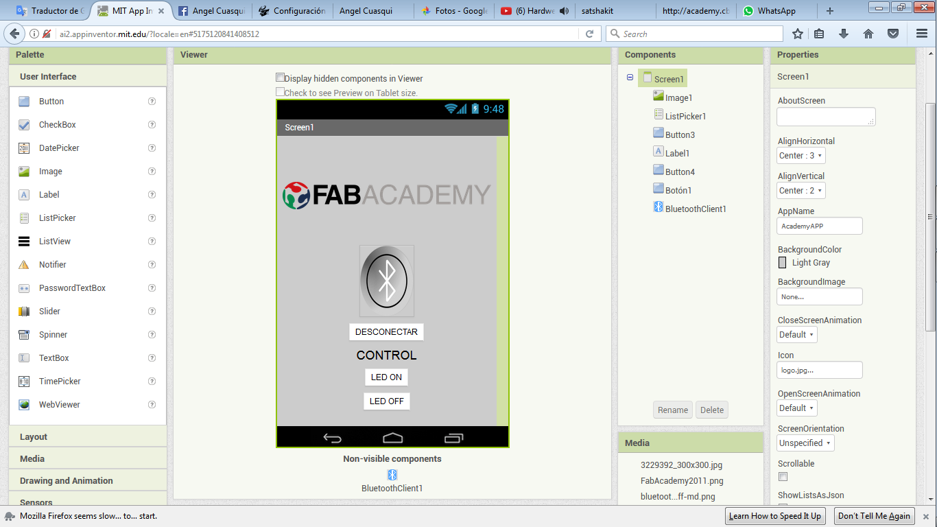
here you can see the block program of my app and the design.
I am working with a Bluetooth interface to send data with my cellphone.
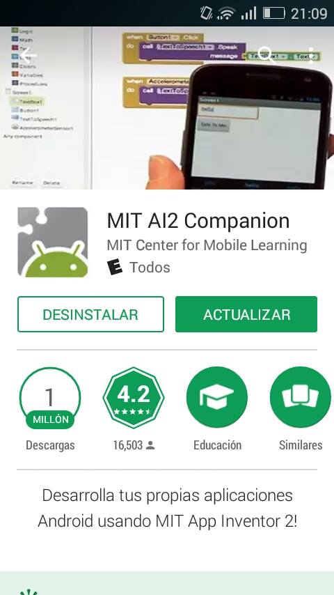
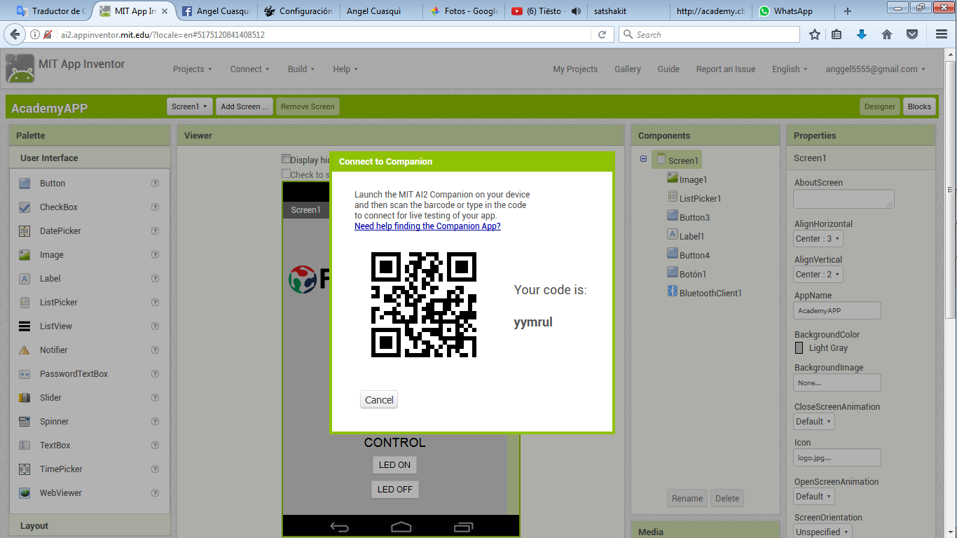
I made the testing with an app to connect to my phone. You can download the app on Play Store, the app is called "MIT AI2 Companion".
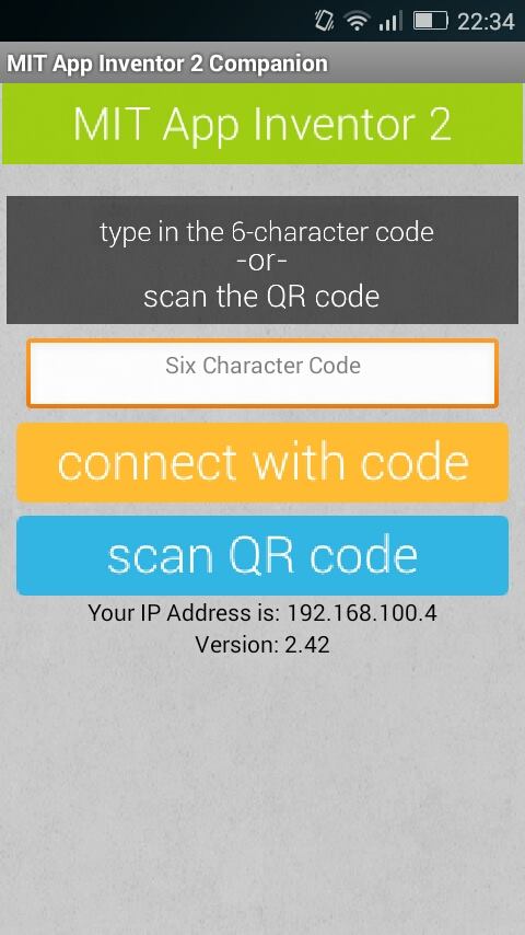
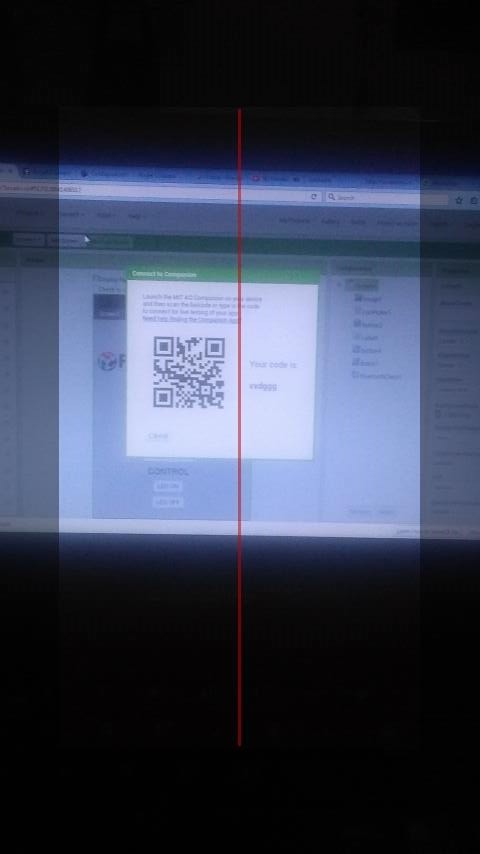
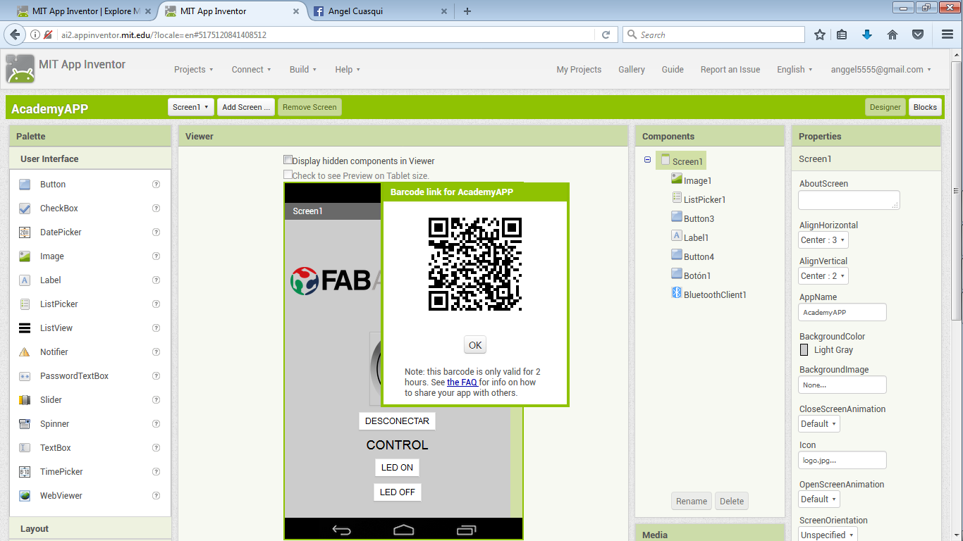
To connect you have to select the option Connect on MIT App Inventor, then the option "Al Companion", it generates a QR Code, you have to scan this QR Code with your cellphone app MIT AI2 Companion.
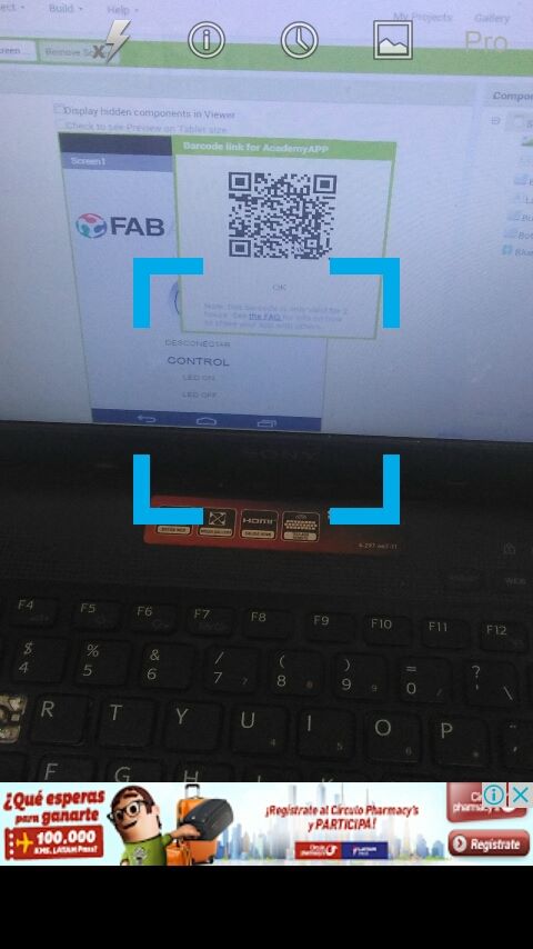
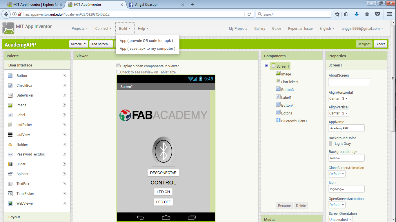
If do you finish your app, you can build your App and download on your computer or create a QR Code to download on your cell phone.
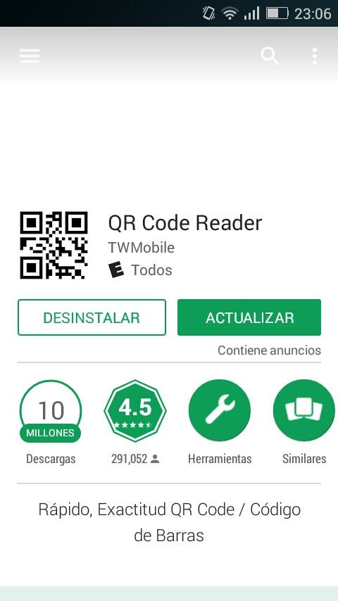
I download a QR Code Rreader on Play Store to dowload my App
To receive the data I am using a bluetooth HC 05 and satshakit, I am using Satshakit to turn on the led on the 13 pin.
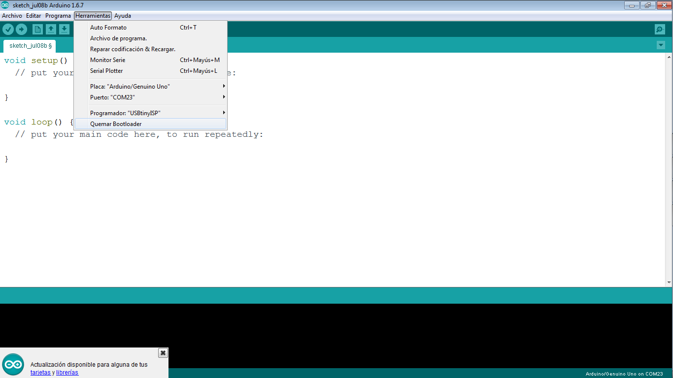
We have to burn bootloaders to worck with satshakit, all the steps to make it you can find
Here
On this page you can find the original files to make your own satshakit.
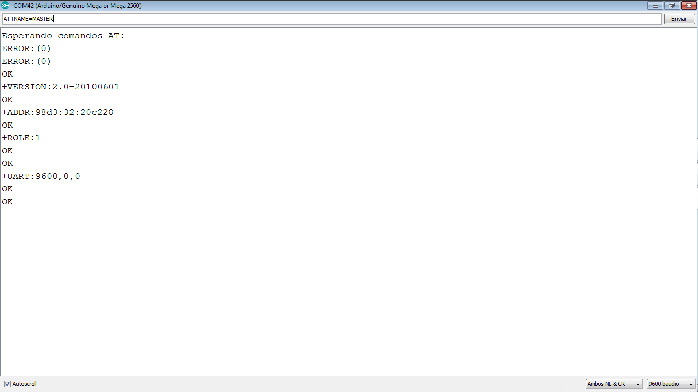
The firt step is configurate your bluetooth. to make it you have to program your satshakit with this code and apply the AT comands to configurate the your bluetooth.
This code is at the final of the page.
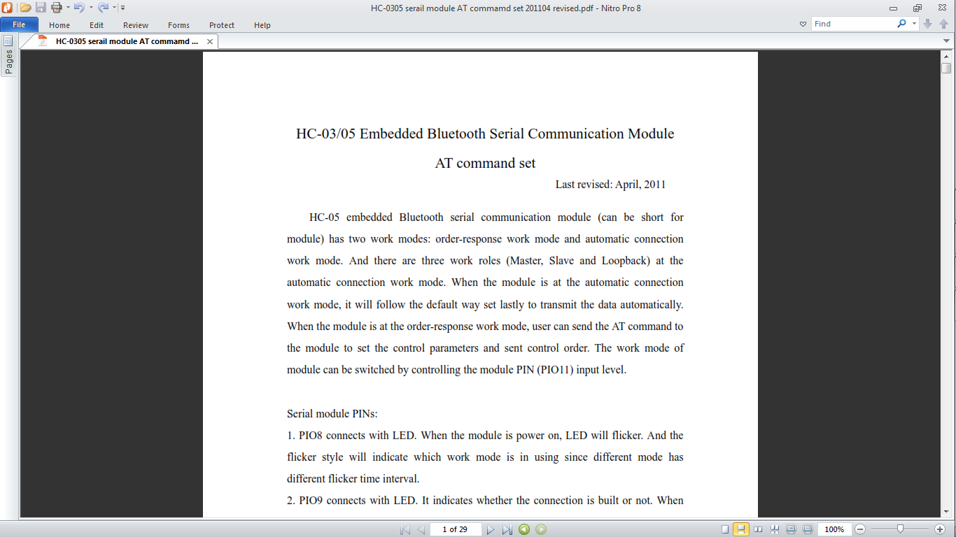
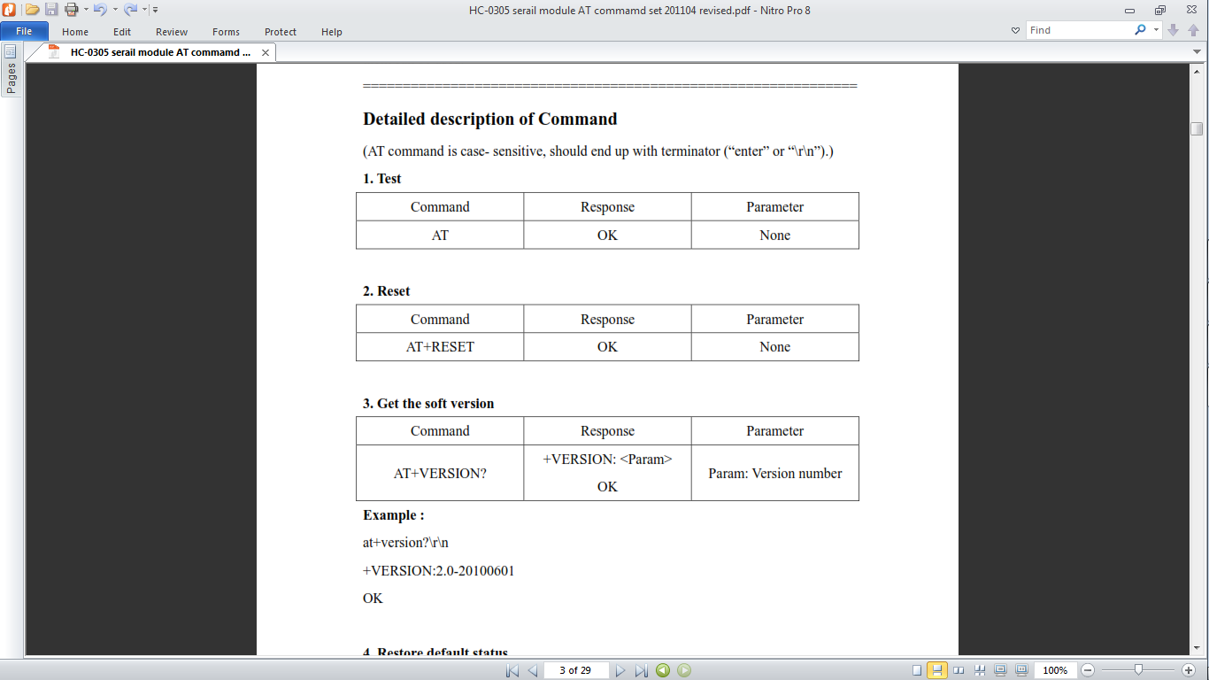
I read a PDF of HC-0305 serail module AT commamd set 201104, you can find this PDF to download on the final of this page.
Also I found a web page about AT commands configuration. Here is the
link
You have to configurate your bluetooth as a slave
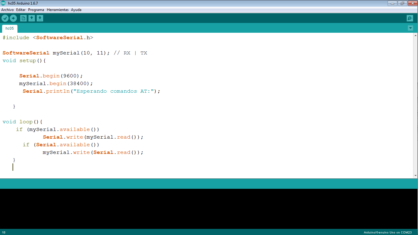
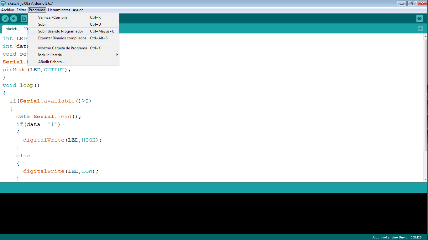
If your bluetooth is configured as a Slave you have to create a code to upload to satshakit, here is a screenshot of mi code and you can download this code in the final of this page.
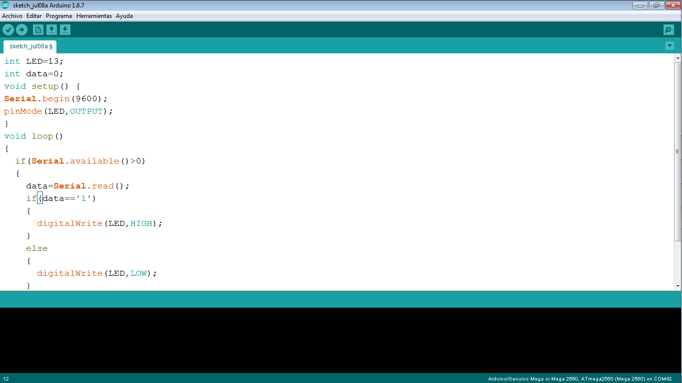
Video
Comment: I am using a "serial communication" to send and receive the data of satshakit with my cell phone
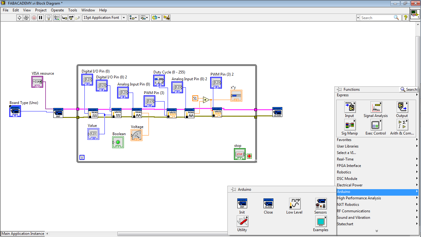
Experimenting with LabVIEW
Also in this assignment I worked with LabVIEW and Arduino. I love LabVIEW because it is really simple, I think it is no really complicated.
My idea is make the same interface with satshakit but I did not have time.
I document it if you are interested in this kind of projects. I that you can change with satshakit or your own board.
You can download LabVIEW on the official page of " National Instruments", you have to create a count, I download a student version software for my assignment.
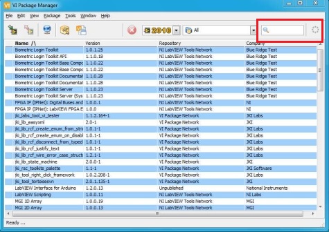
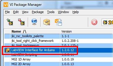
When you install LabVIEW you need a complement to do the interface with Arduino, you have to download VIMP, I am going to put this file on the final of this page. when you have installed the VIMP, you have to looking for on this software Arduino on the magnifying glass, then a file called "LabVIEW interface for Arduino". you have to install this complement.
I found this video tutorial to make this installation on Arduino complement.
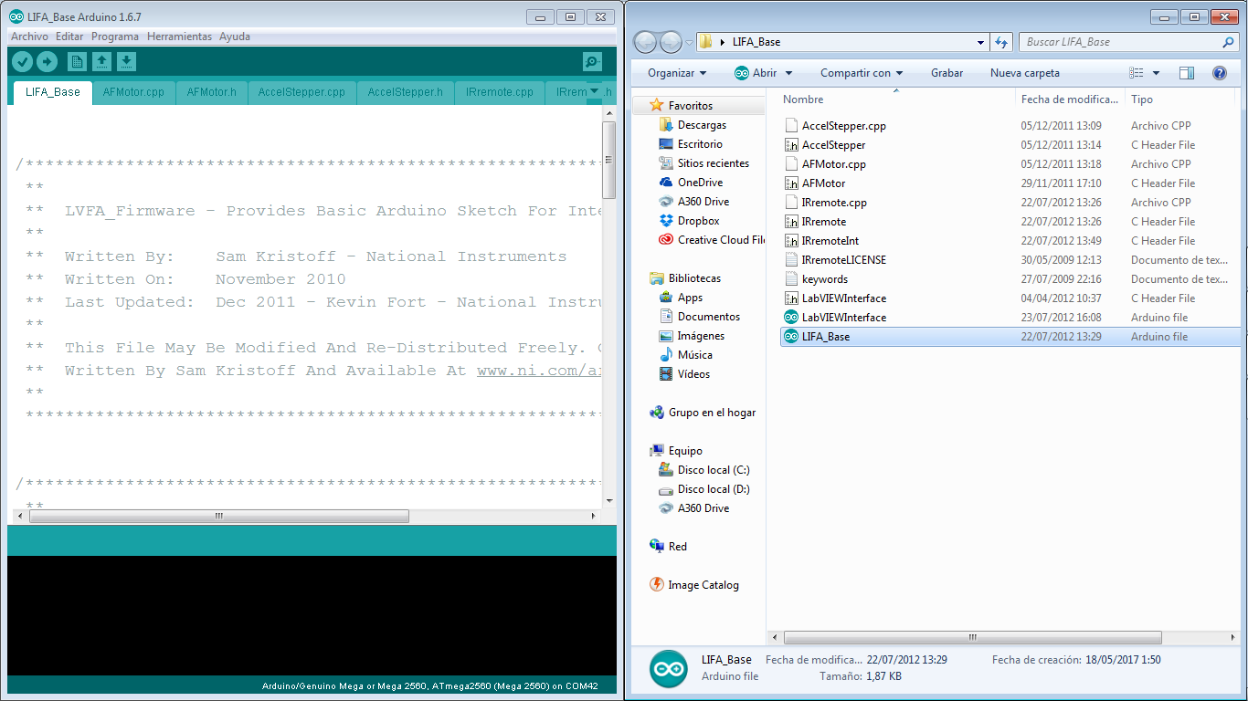
Ok, when the complement is ready, we need to upload a file on Arduino,satshakit, fabkit or your onw version of arduino. this file is called LIFA_Base.
After, you have to program on LabVIEW, I find a file about Arduino and LabVIEW, this file has examples, it is a complete tutorial how to work with Arduino and LabVIEW. this is a PDF file and you can download in the final of this page.
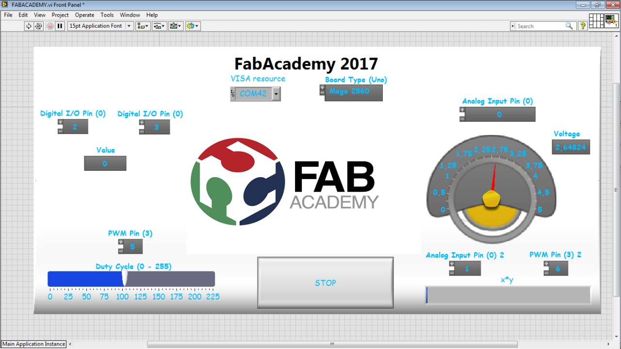
My idea was connecting it and simulate with variable resistance, it is really similar to a sensor, you can change it for a sensor, I use it because it is an easy way to demonstrate the analog function, also and added a led with a button, the brightness control of a led with a slider on LabVIEW, and the brightness control of a led with a variable resistance. it is my window on LabVIEW, I added an image on the window, if you want to add an image you just have to drag the image to the LabVIEW window, it is really simple.
this program is down to download.
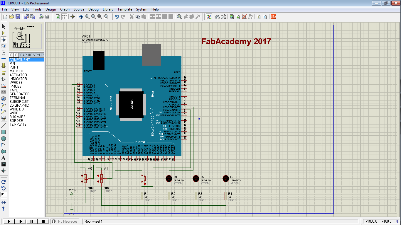
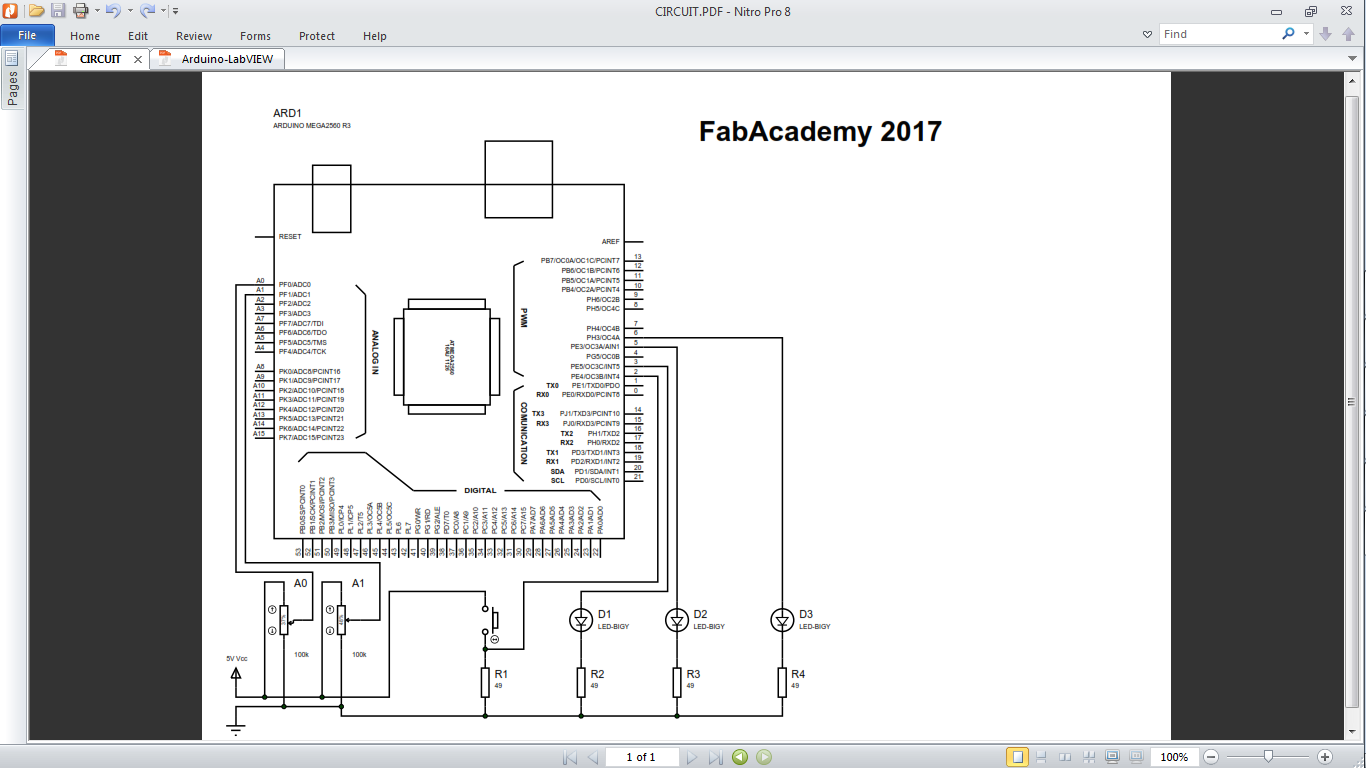
Also I created a file to understand the way to connect the components on your PCB pins, I created a circuit on Proteus. and a pdf file of this circuit, to download you can find it down and the proteus file.
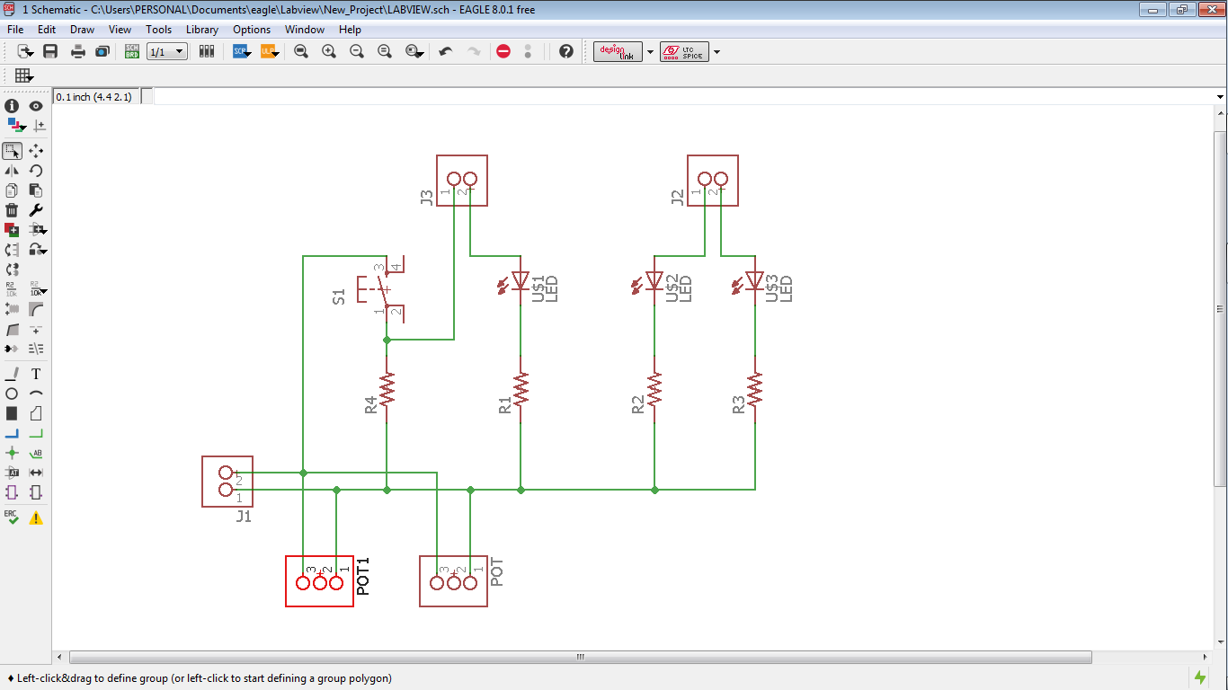
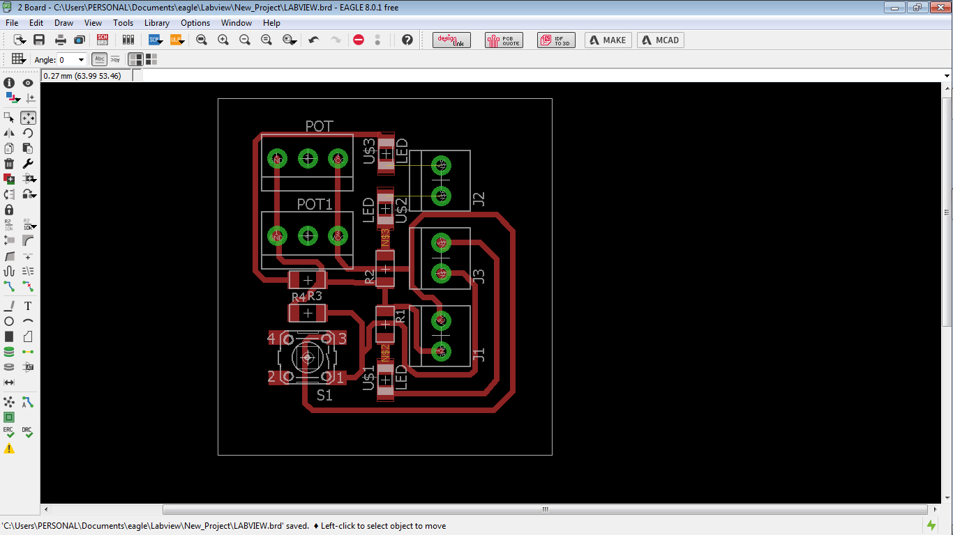
If you want to create a PCB I created a PCB to connect the components with Eagle PCB software, you can find this files in the final to download.
Video