Molding and Casting
Design a 3D mould, machine it, and cast parts from it.
fusion 360
For this assignment I use the software Fusion 360 to make the design and modify the parameters for gcode to the machine, the software is very complete and easy to use, inside
of the software you can find a help to guide how to use the deferent process of the software.
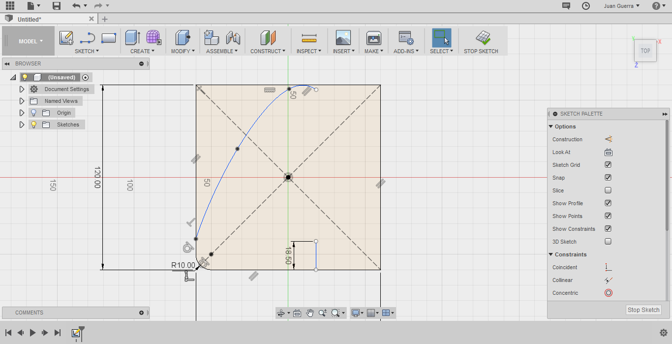
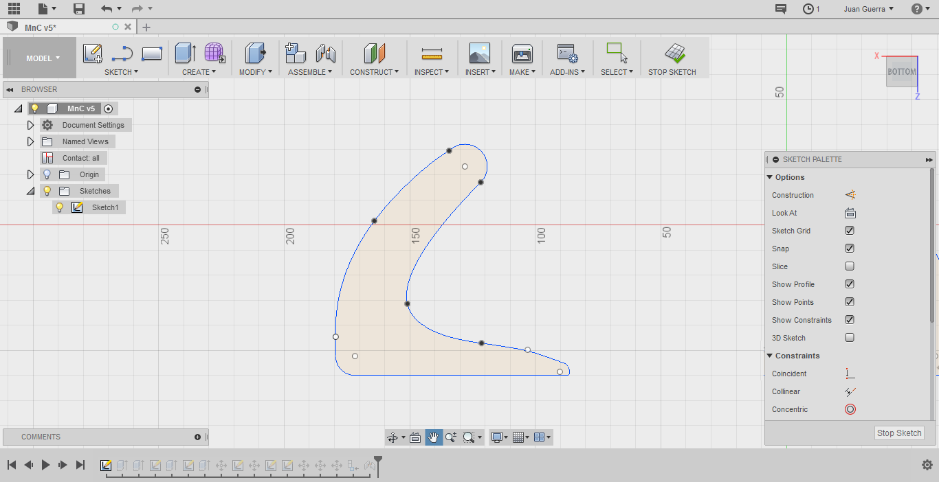
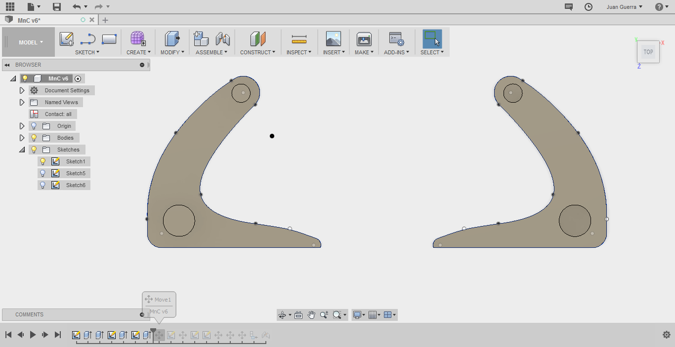
First, design the object for this first start with the command square give the dimensions of the object, next with the command fillet, round one corner of the square with a
radius of 10 and finally with spline command make a line like the principal idea.
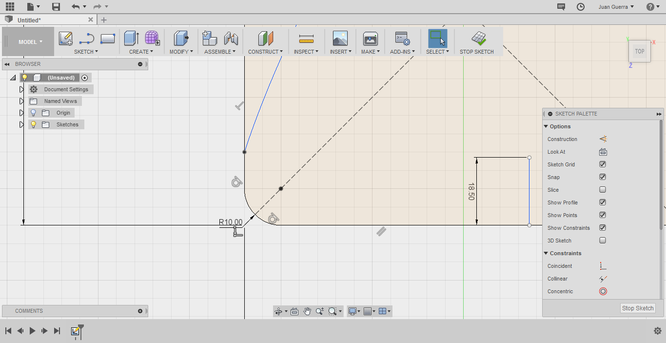
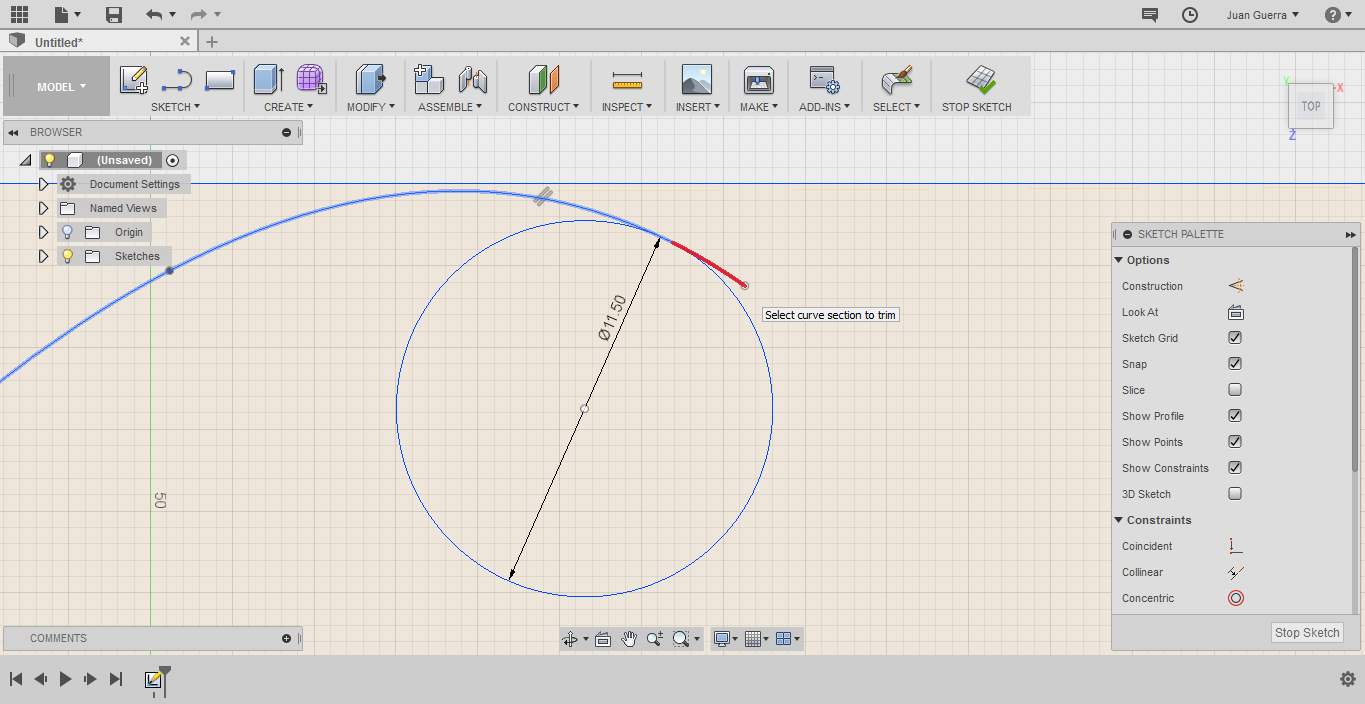
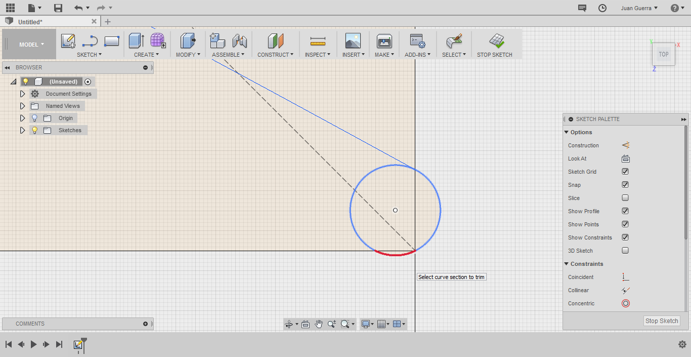
At the end of the line that we made, draw a circle of the radius 11,5 and another corner of the square make a circle, the with the command trim remove the all excesses, to
finish the 2D design join the two circles with a line with a command spline based in the design.
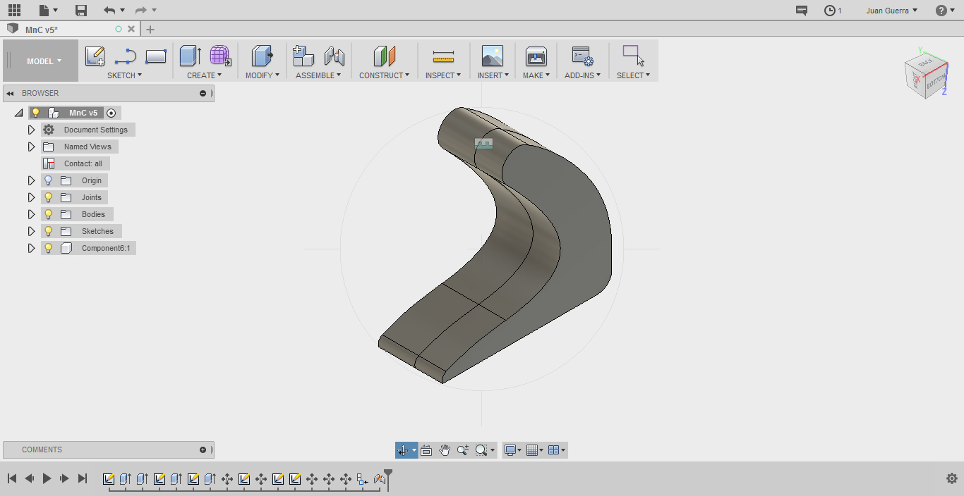
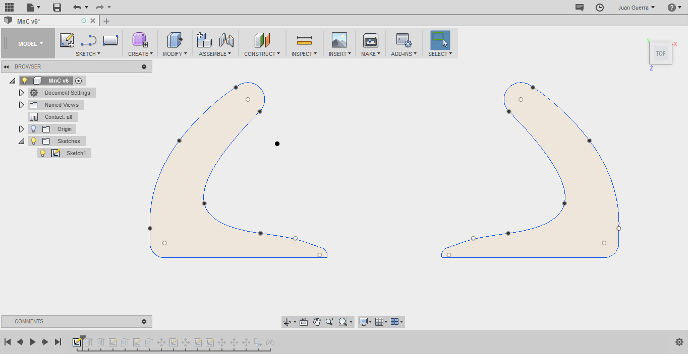
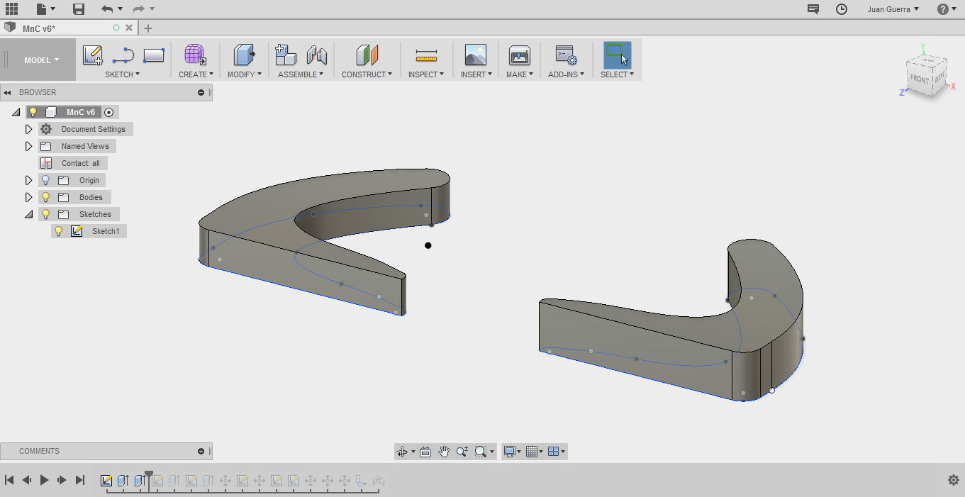
To begin the design 3D, in the before sketch with the command mirror duplicate to another part of the mold, to make a 3D object you can use two different commands extrude
or press pull in my case I use press pull, one commands are in create and modify in the toolbar, the measure to extrude is 1,5 and 2 cm because the wood to work is of 20 mm.
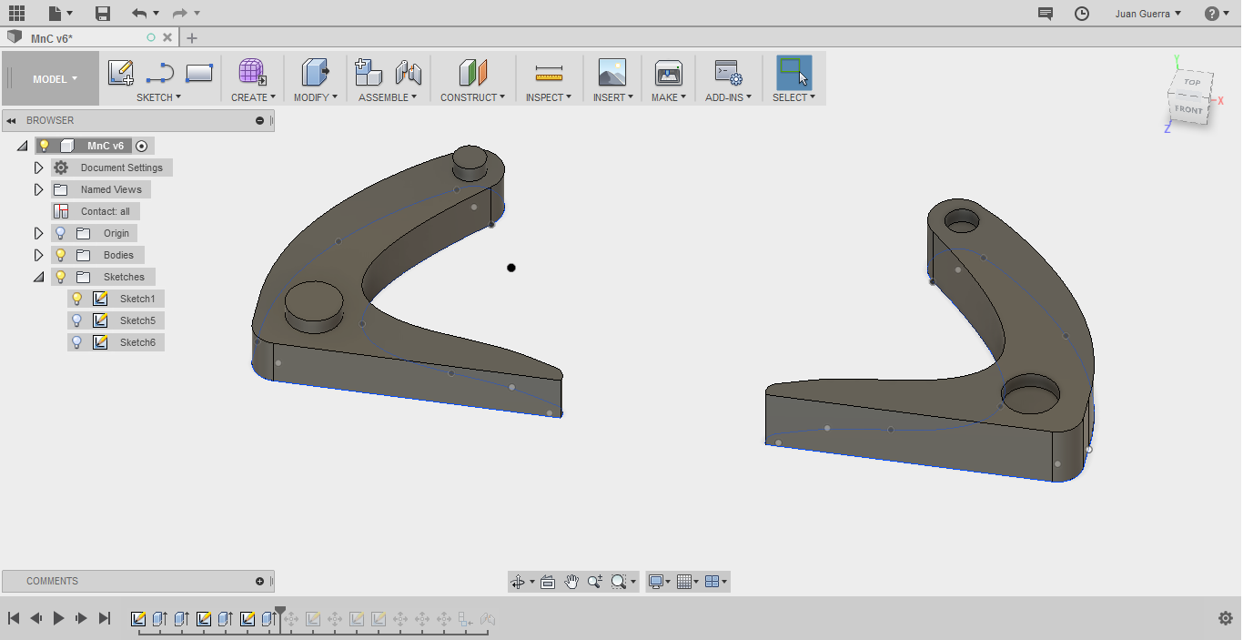
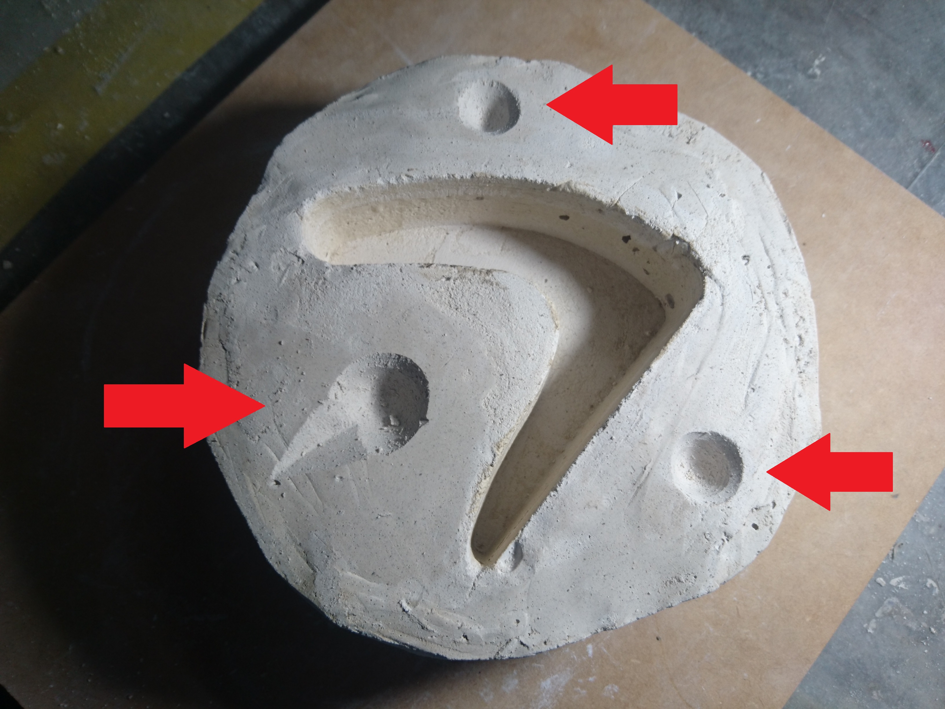
For the las step in 3D design make the assembly points, for this make two circles for each piece and the difference of the measure of circles is 1 mm to make press fit and
this measure it varies of type of material.
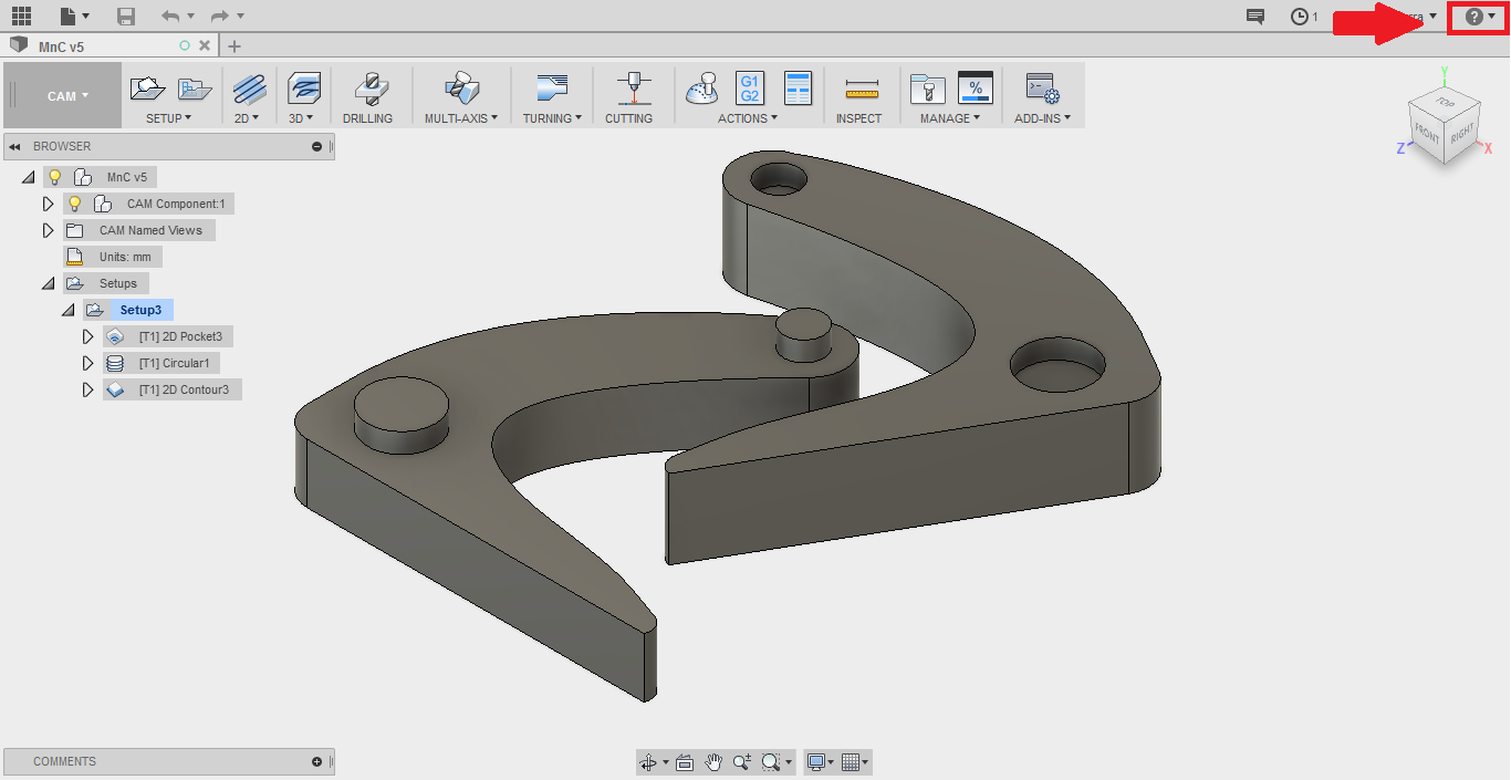
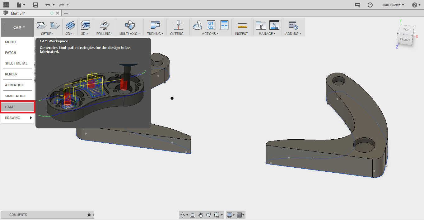
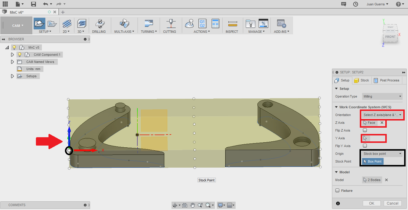
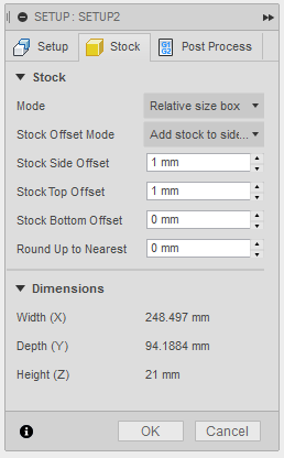
To export the gcode firs change the function of the software and select cam, next choose a new setup and here select of the point zero and the position. In orientation you
select the axis to change then you choose with a click the axis x, y, z. next in stock you specific the excesses of the material.
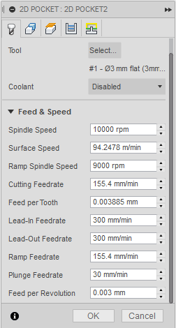
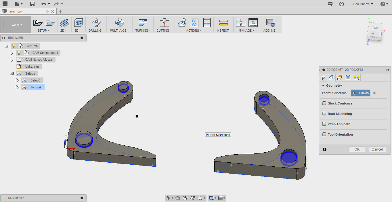
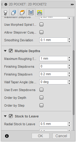
Next use the tool pocket to remove the first part to make circles, in the first parameters in “tool” select the mill and all the specifications, next in geometry select the
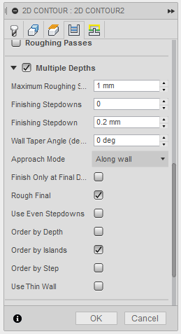
surfaces to make, next in passes you select multiple depths to the depth the depth that the mill will remove and press OK.
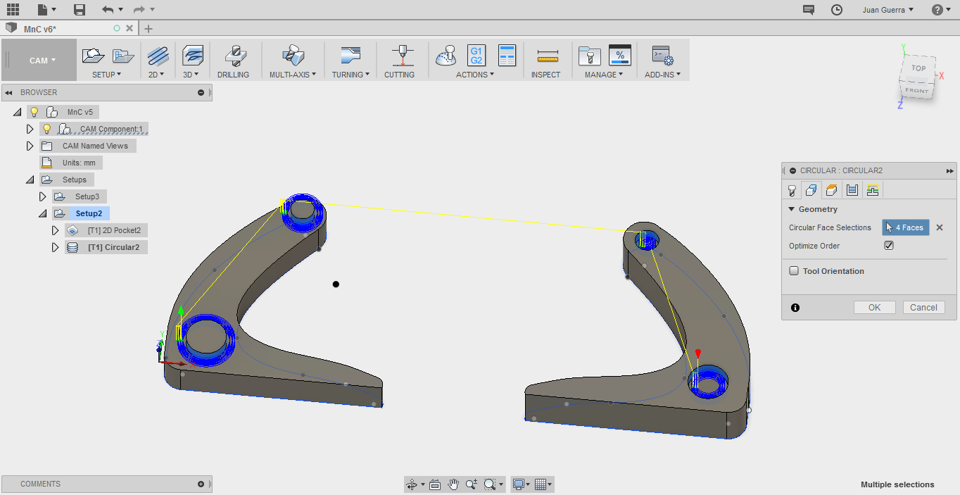
The next step is circular to make the circles at the measure specific, in geometry select the side surfaces to make the process, in passes you can select the numbers of times
of the mill remove the material in side surface and numbers of time to depth.
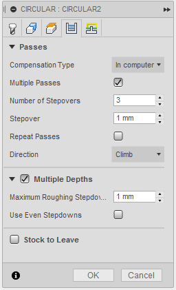
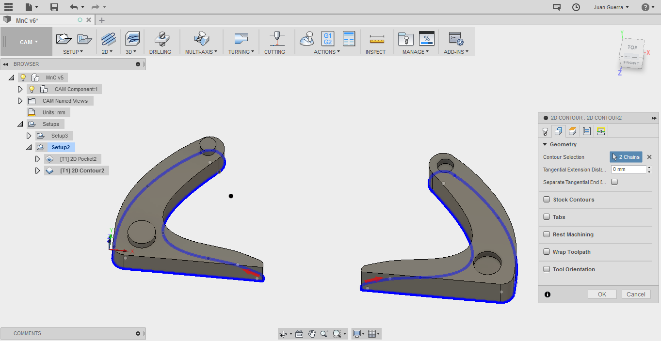
The last process is the contour, in geometry select the contour in the base of the piece, and modify the multi depth.
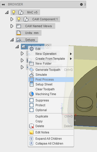
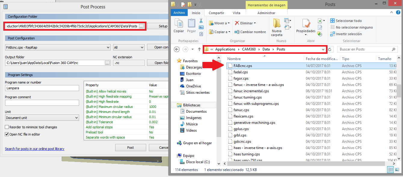
Then in your setup with a right click and select post process, if you have a fabtotum in the direction you can add the specifications of this machine this file you can find in
the fabtotum page or in the files at final, then close and open again and export the gcode.
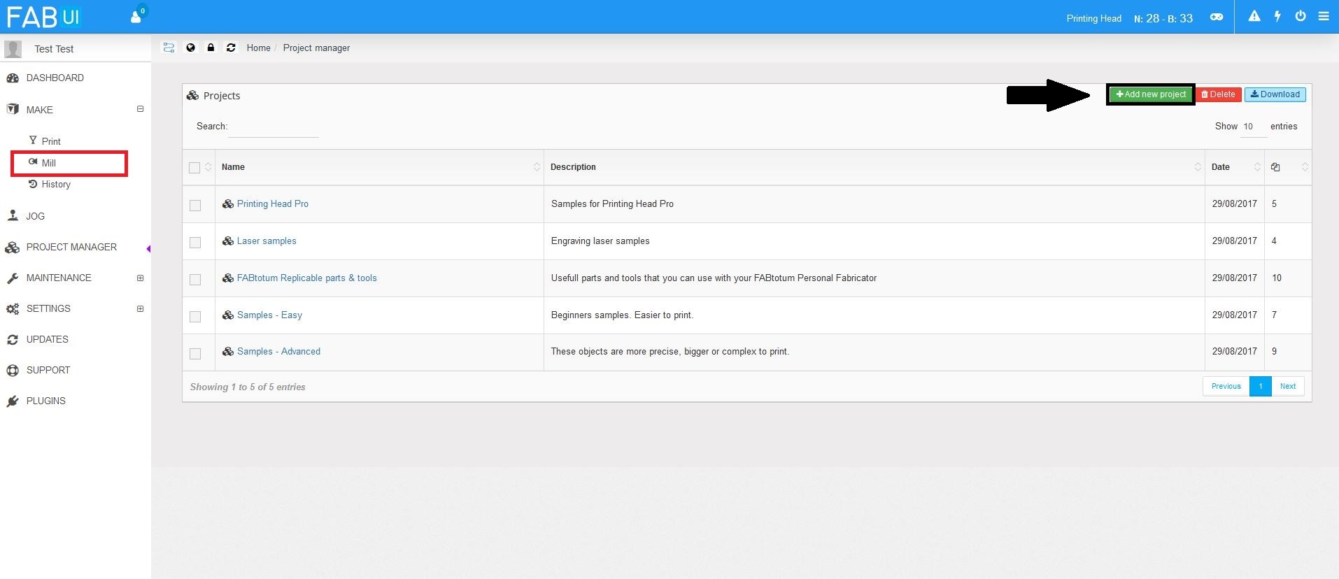
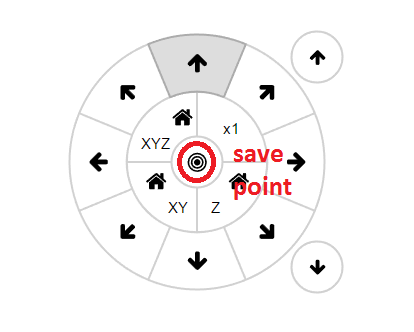
In the machine first add a new gcode to milling, then press in mill to make the file, you select the file and in the next step with the control panel save the star point and
press mill to begin making the file.
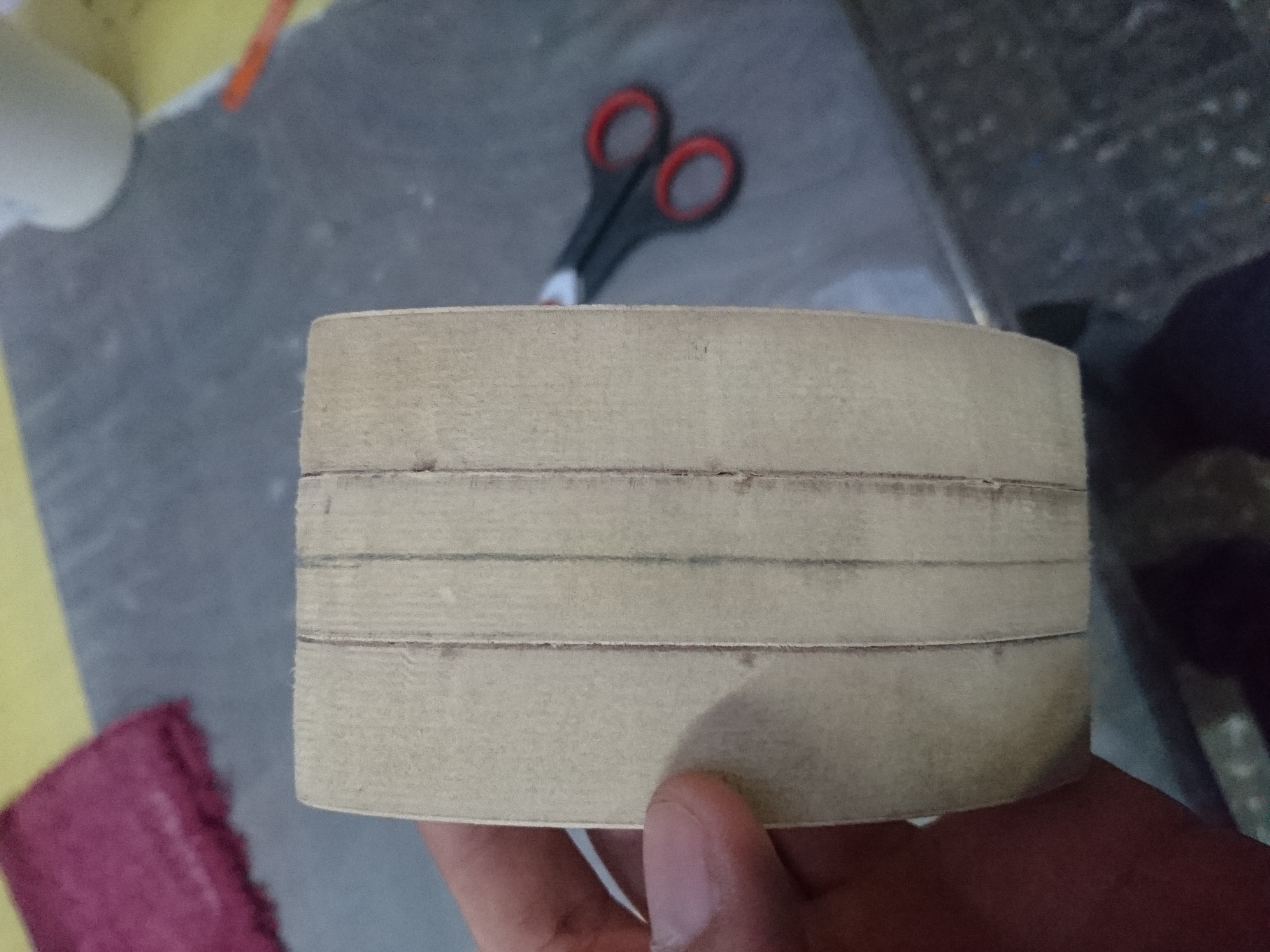
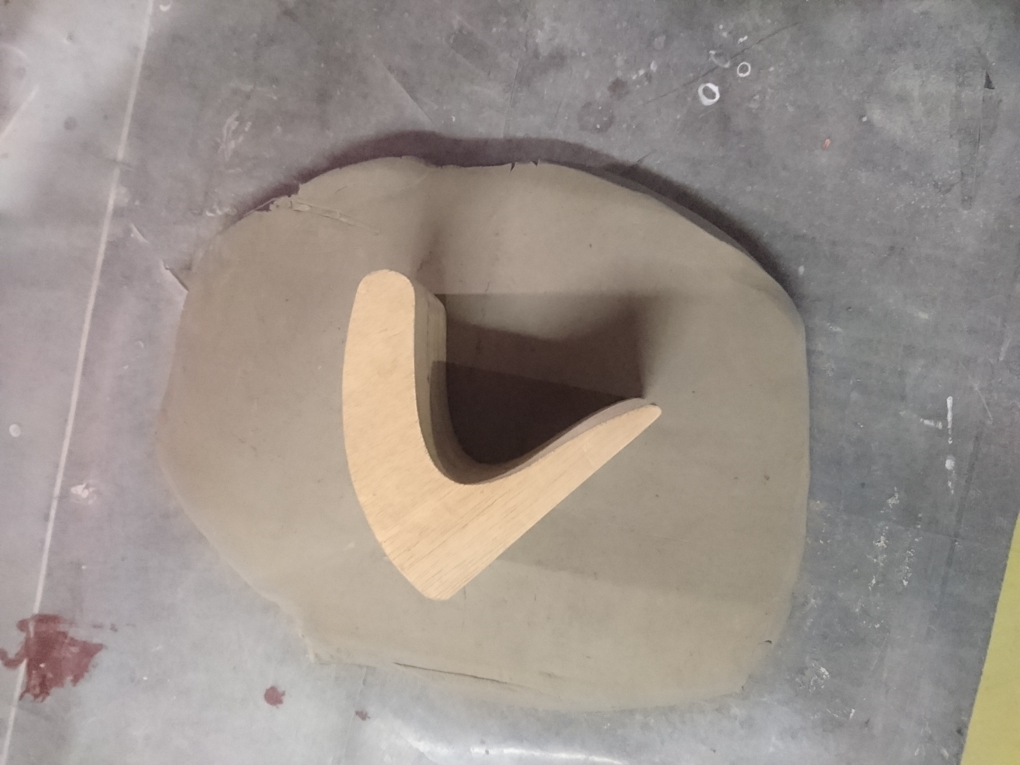
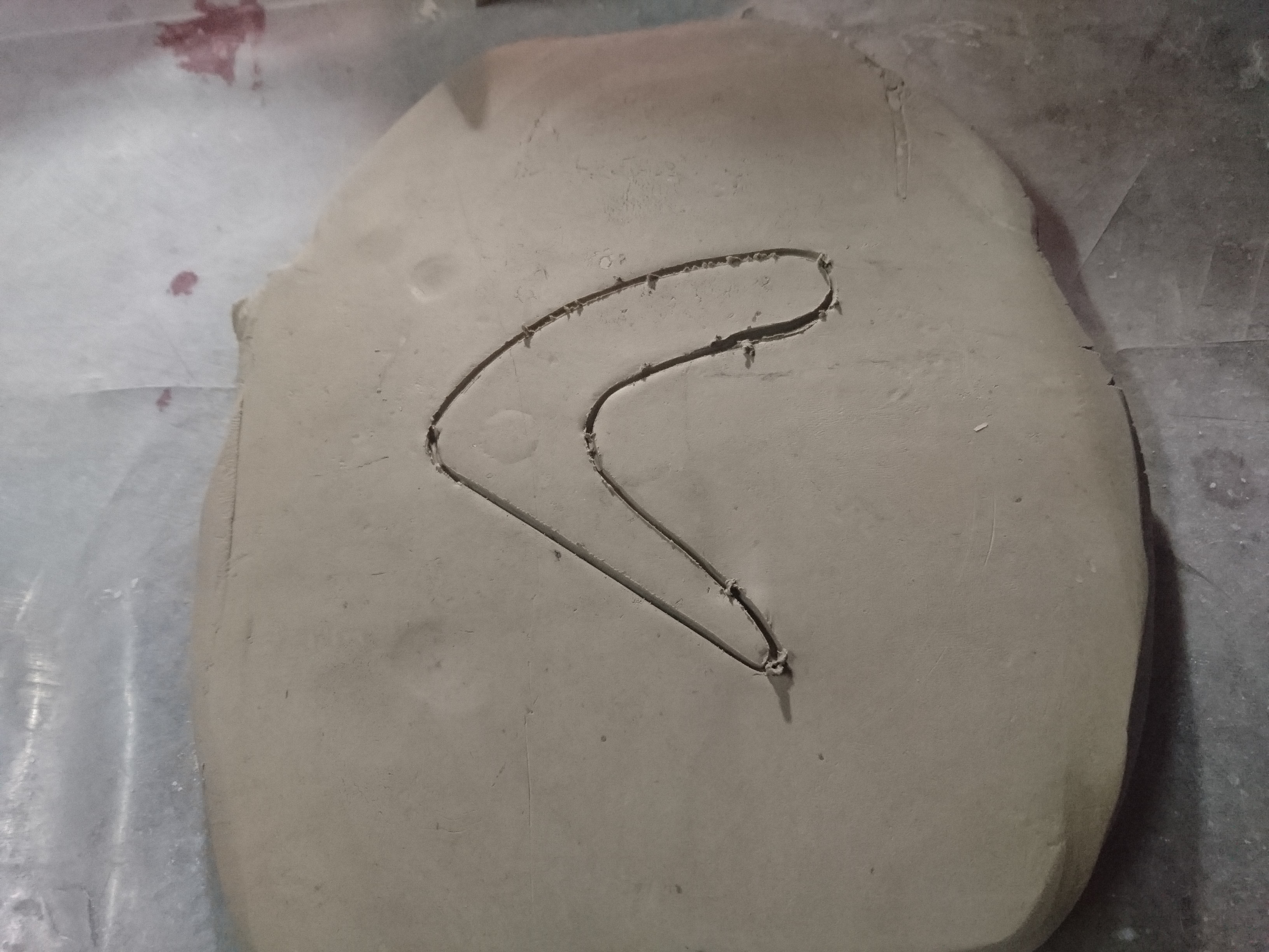
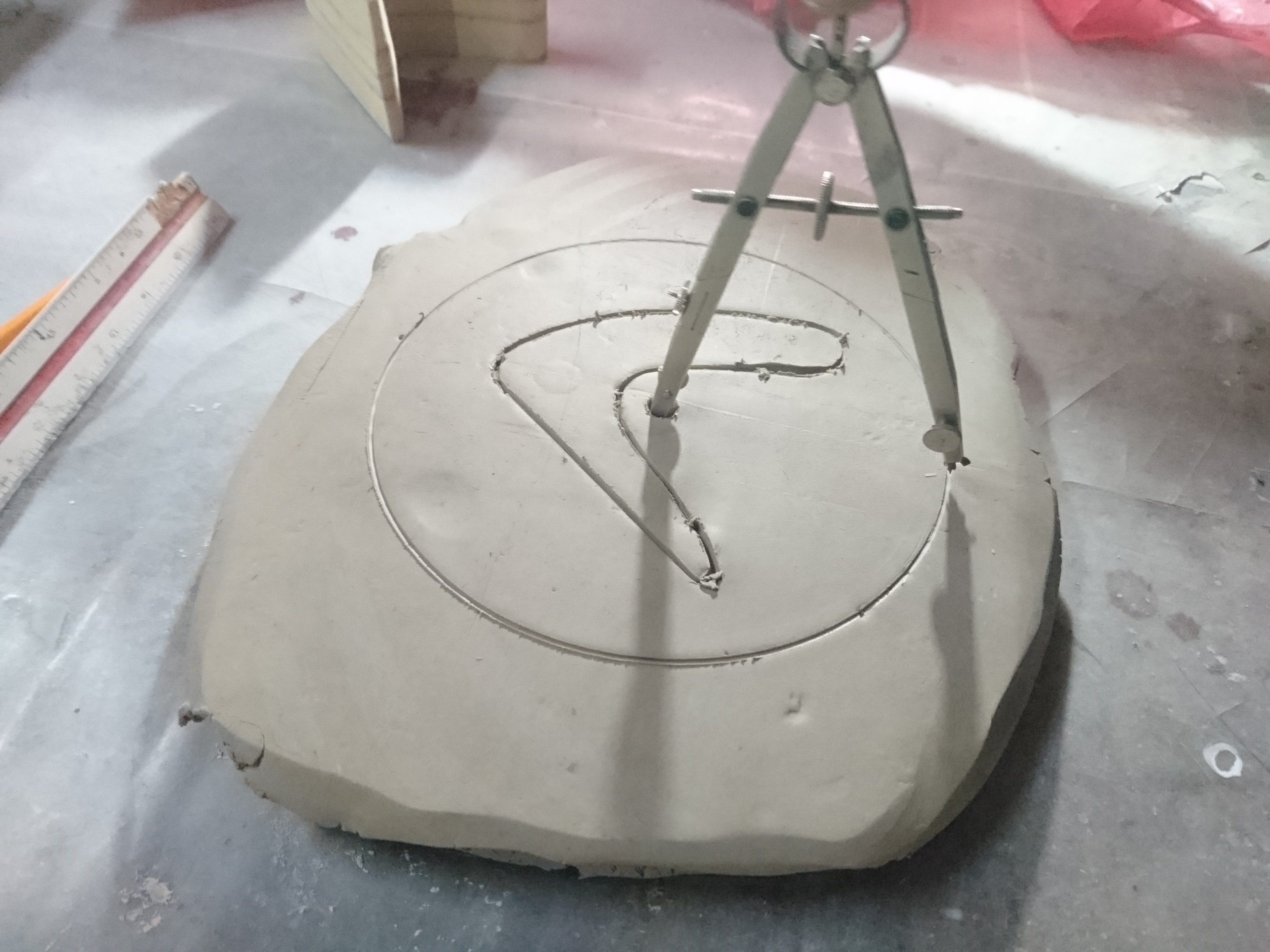
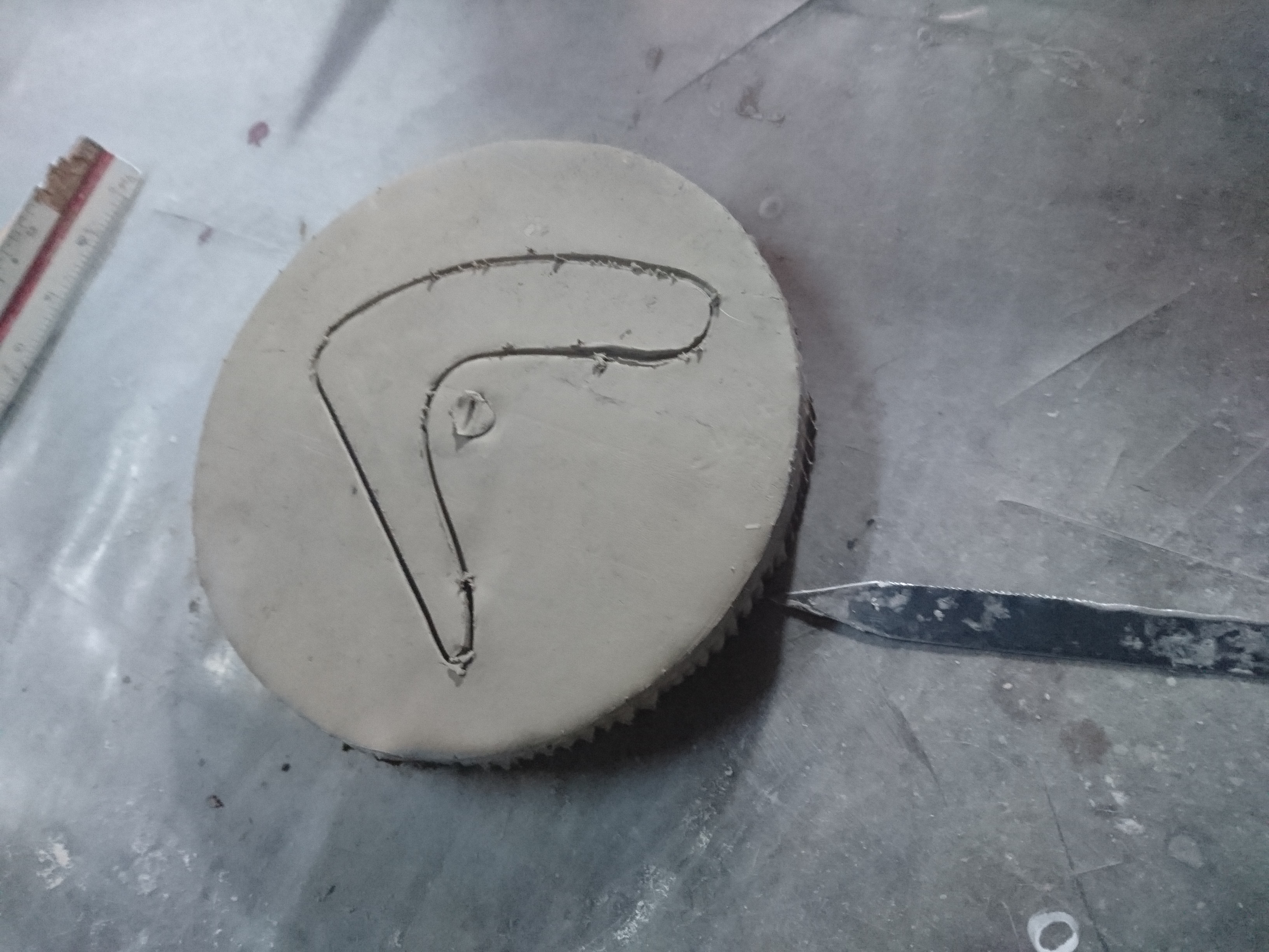
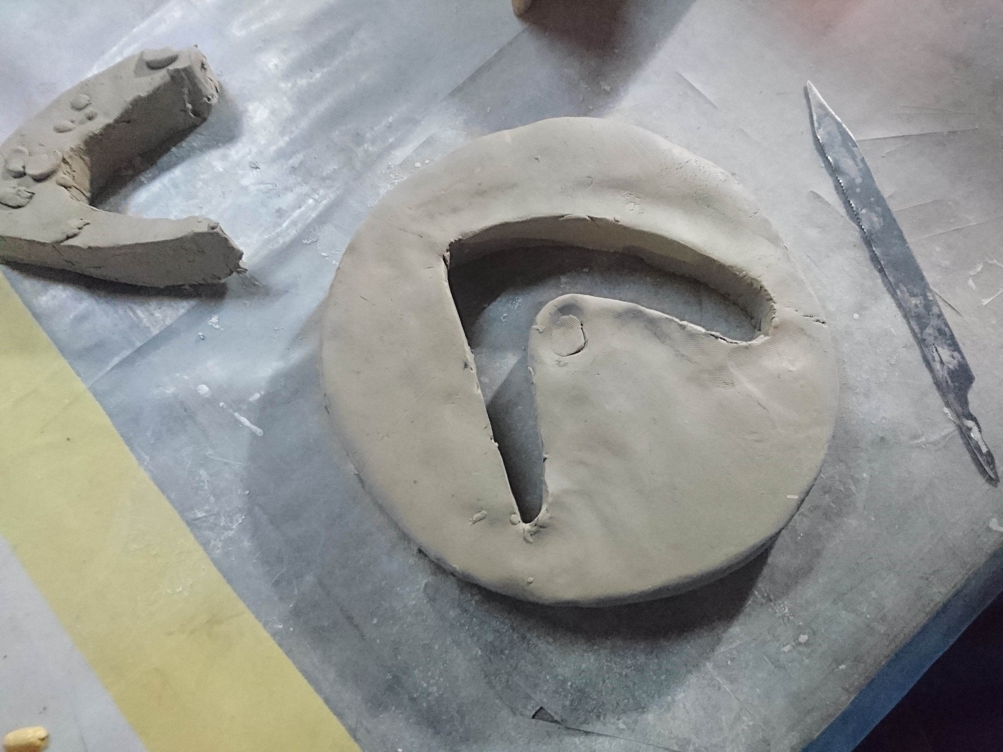
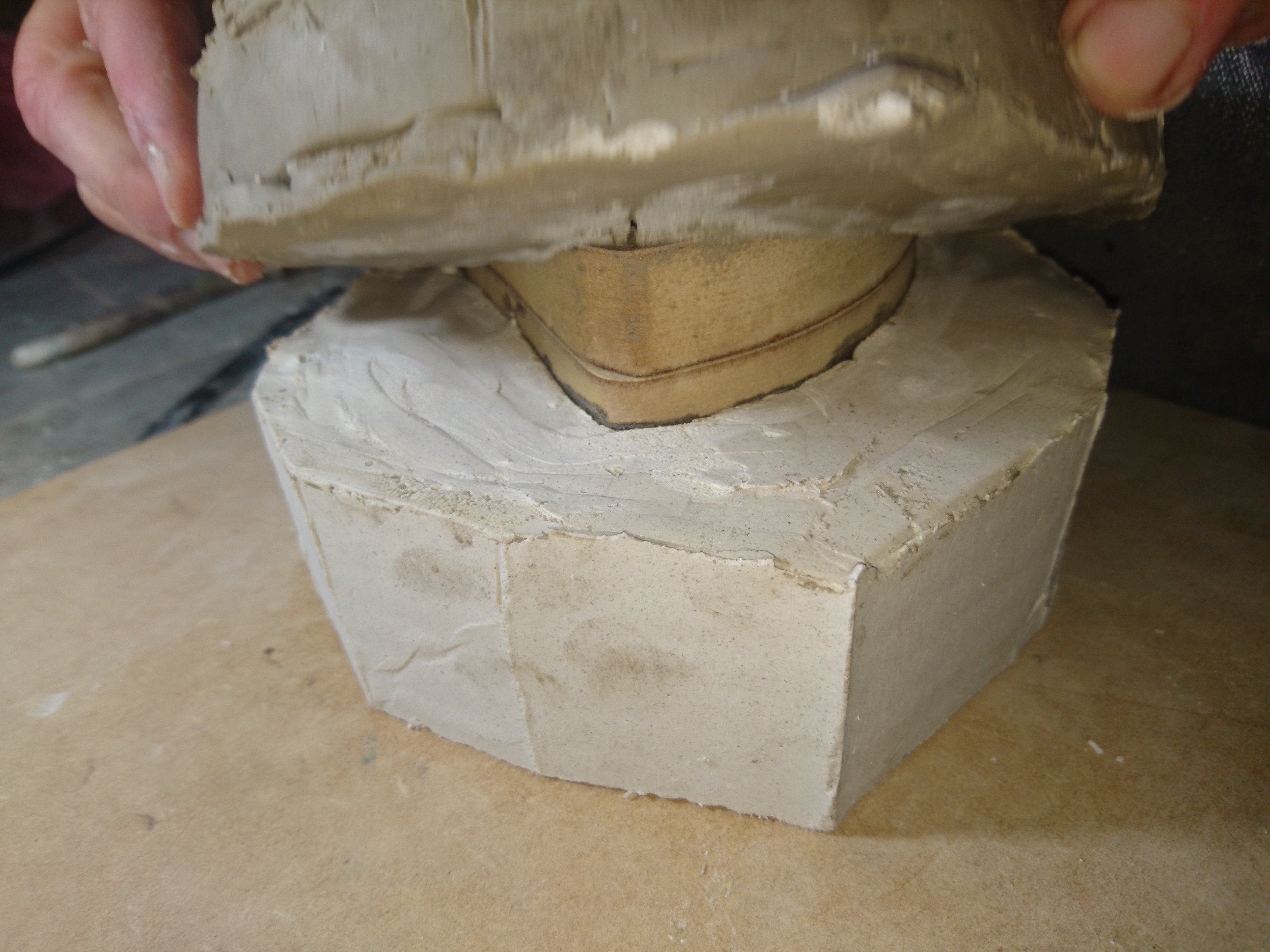
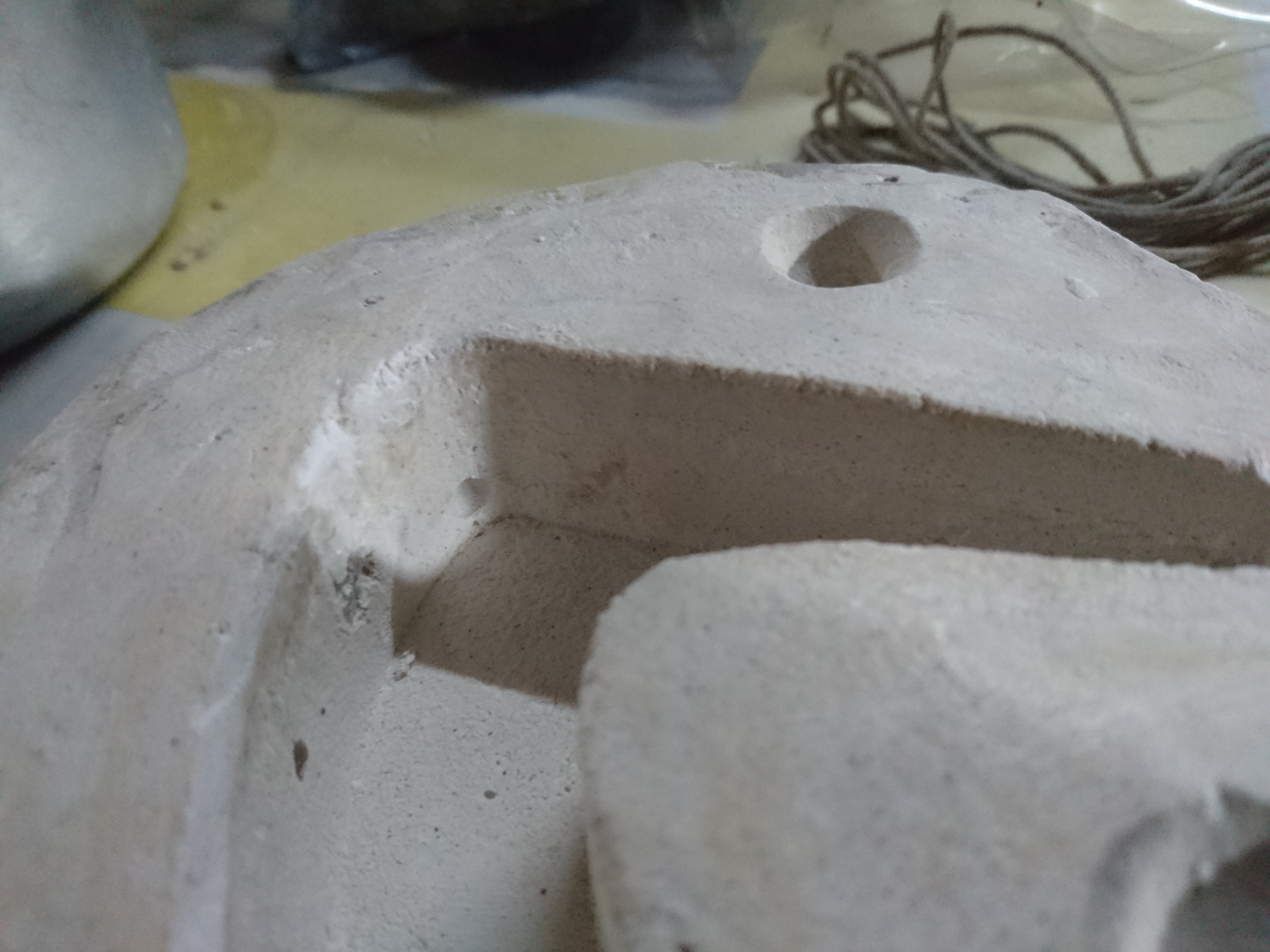
In the process to make the mold first mark the middle of the piece and with ceramic clay make the base of the mold, for the base in ceramic clay make circle with 3 cm more of
the piece, then remove the excess of the ceramic clay.
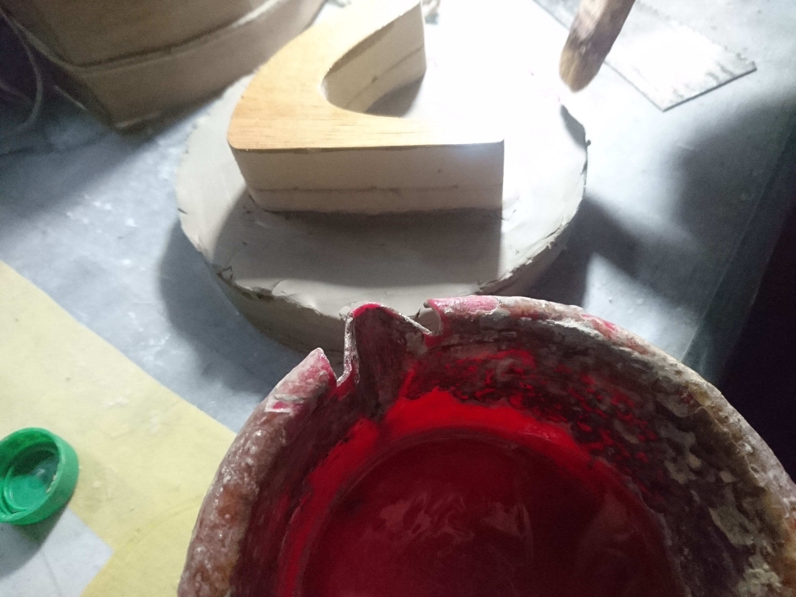
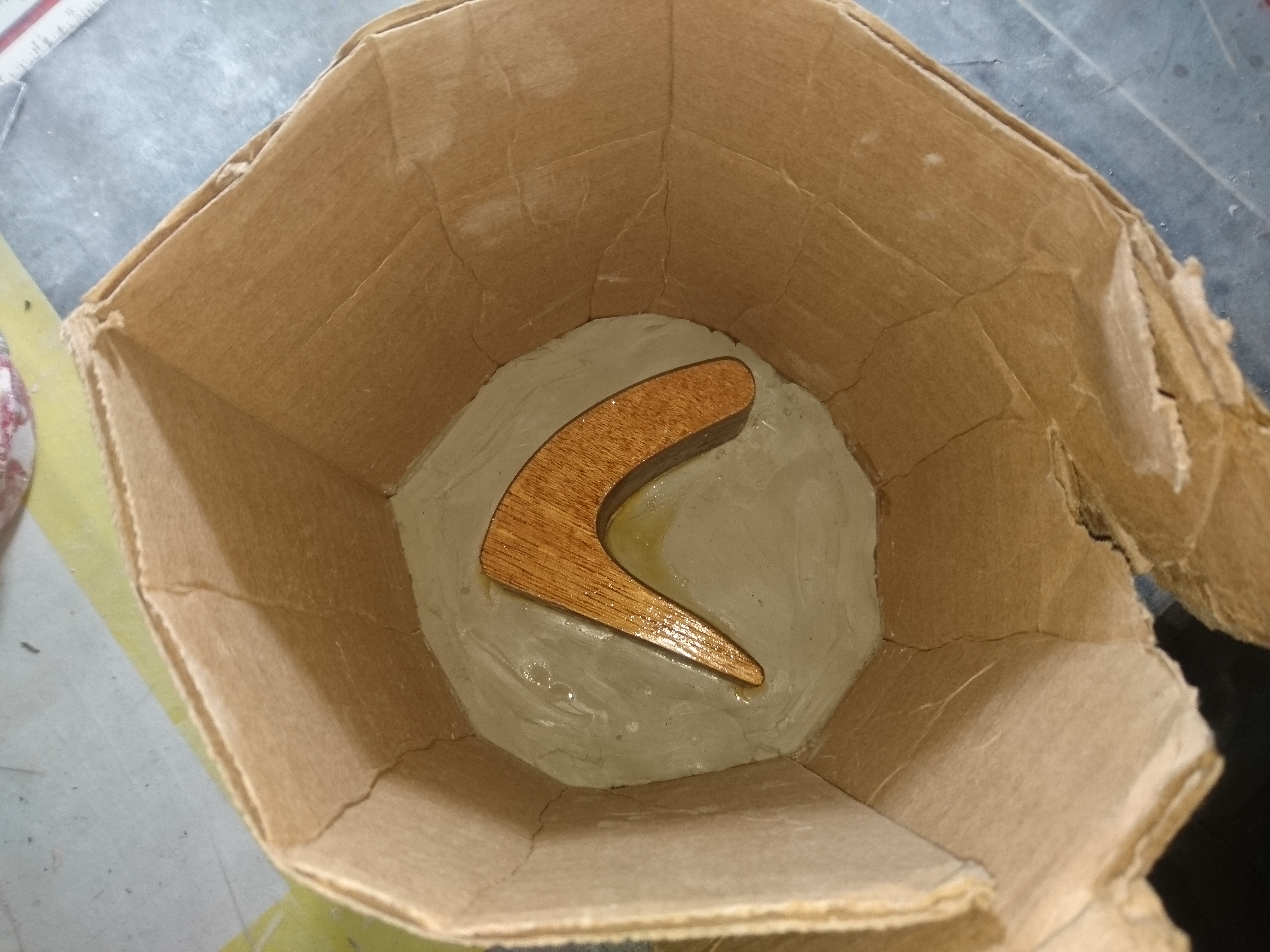
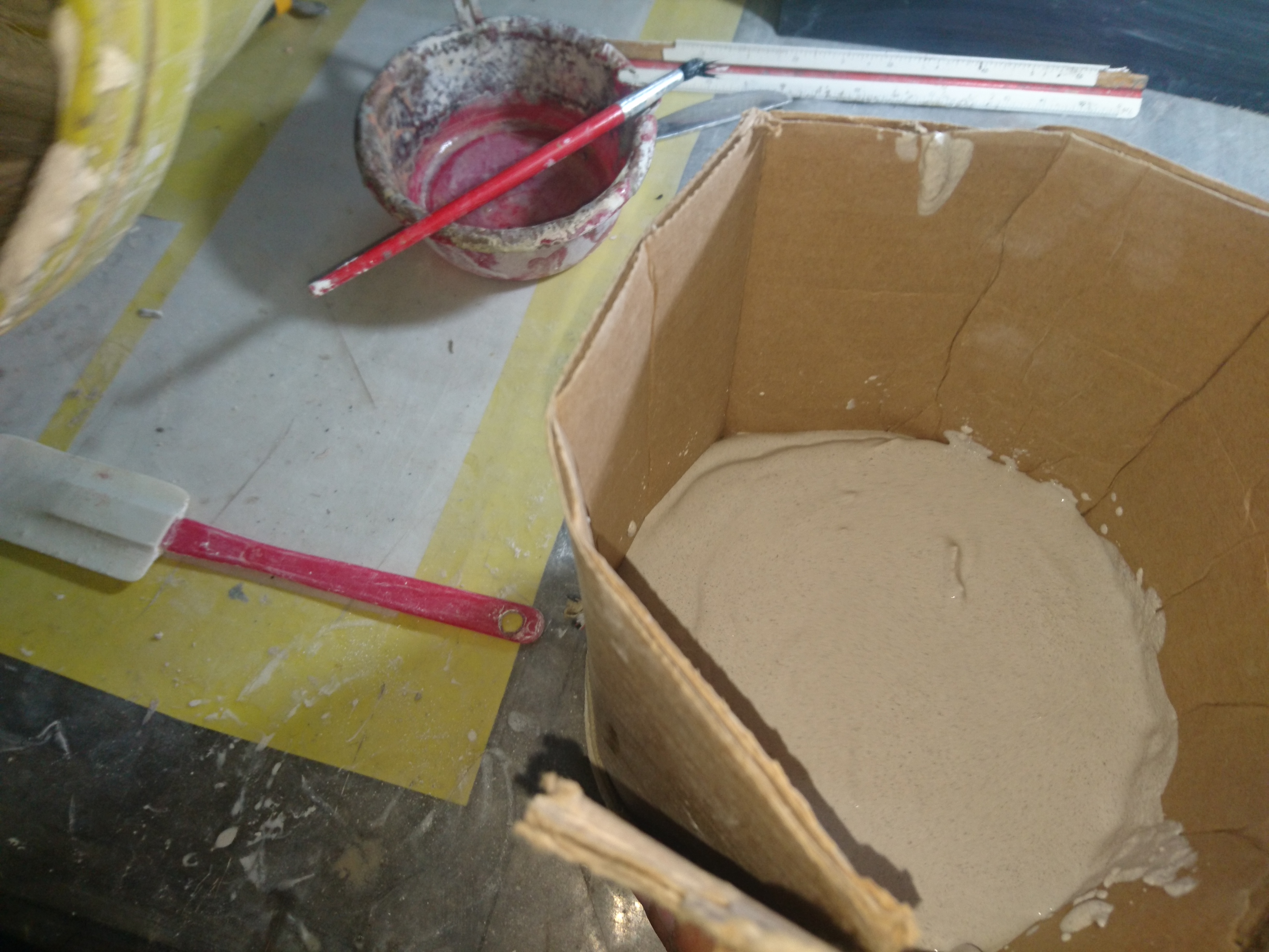
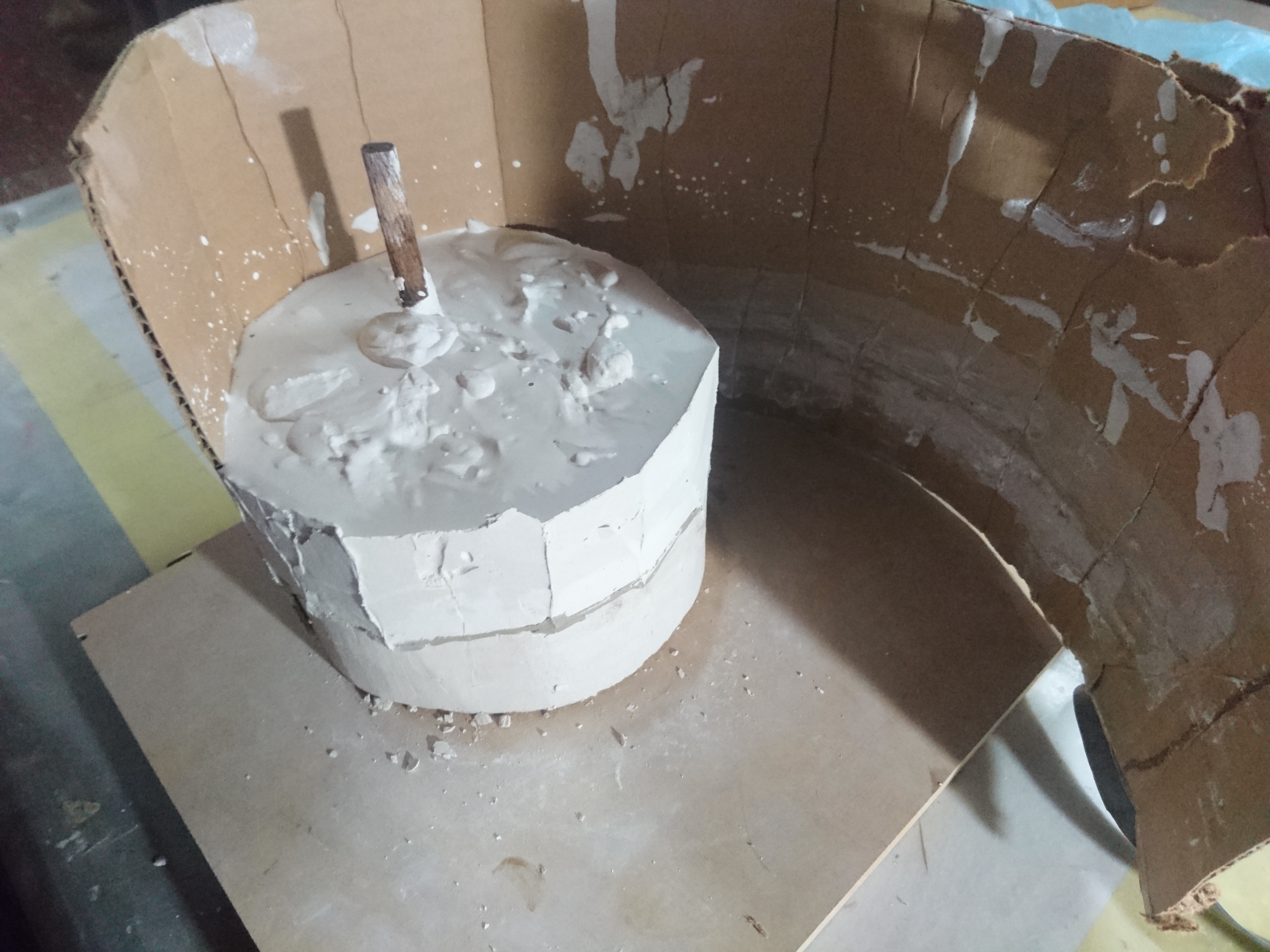
Now, from the uncovered side of the mold we anoint release agent so that the plaster does not stick, then surround it with cardboard and we cover the holes with more ceramic
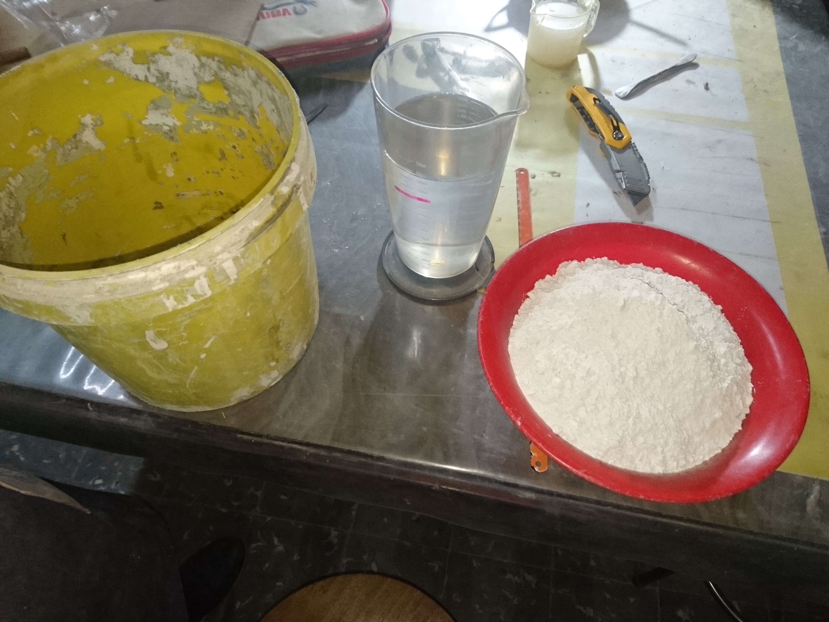
clay, mix plaster with water, plaster 60% and 40% water, and immediately put inside the mold, shake it little so that the bubbles come out, wait for it to dry, remove the
cardboard and the ceramic clay.
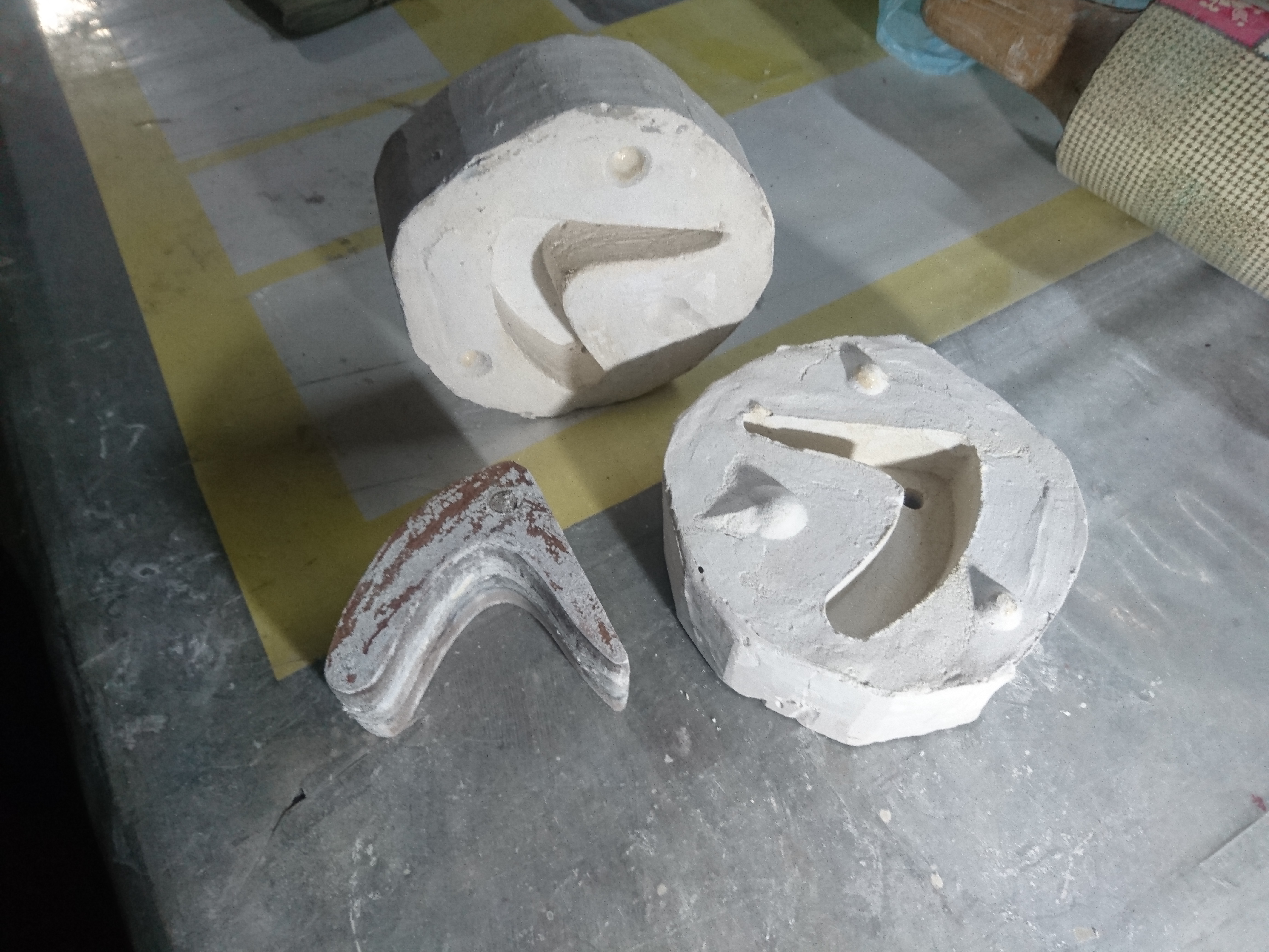
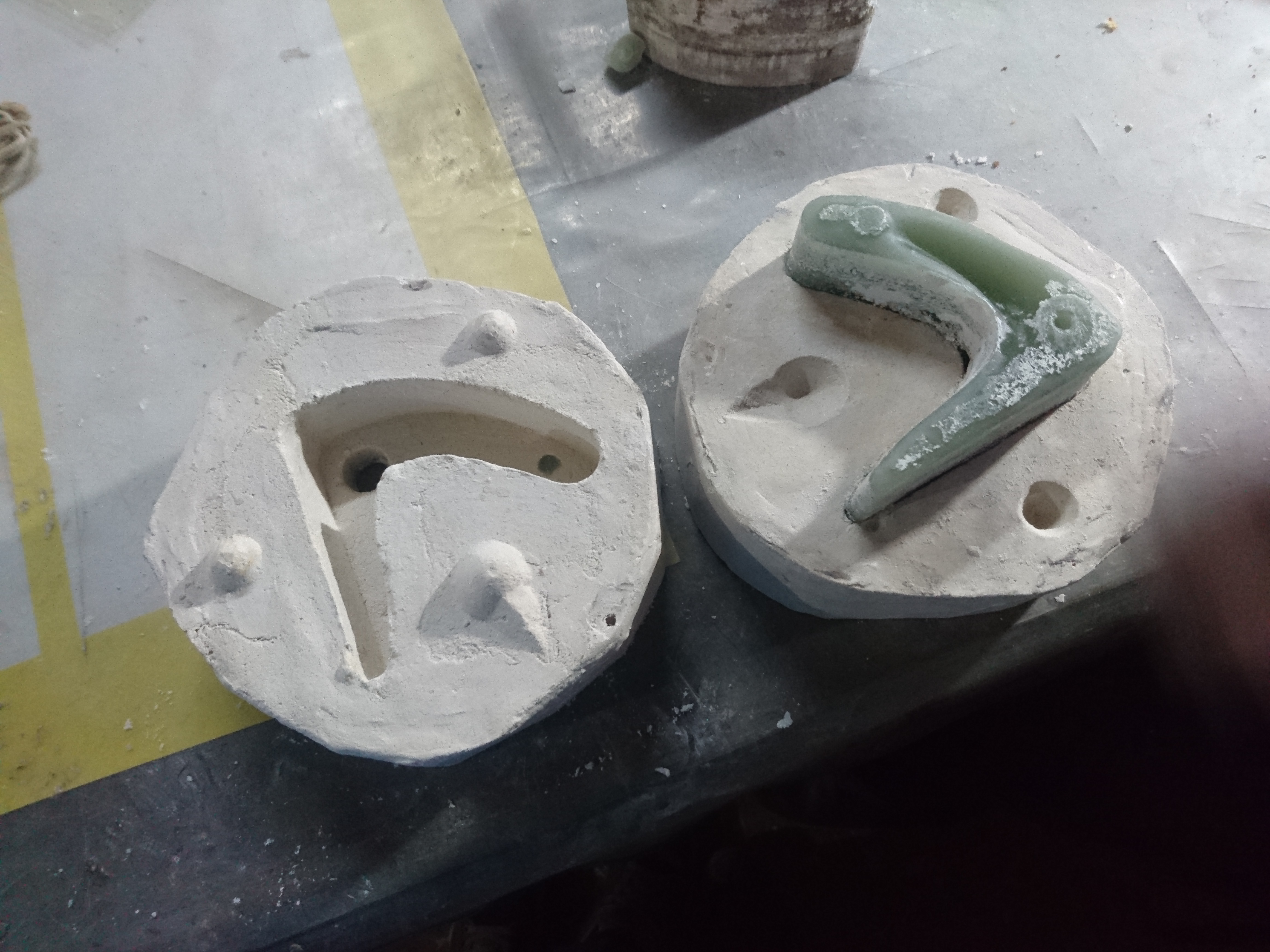
To the other part, first mark the position of the mold, the mold makes the same process and add something where the liquid enters the mold and open it.
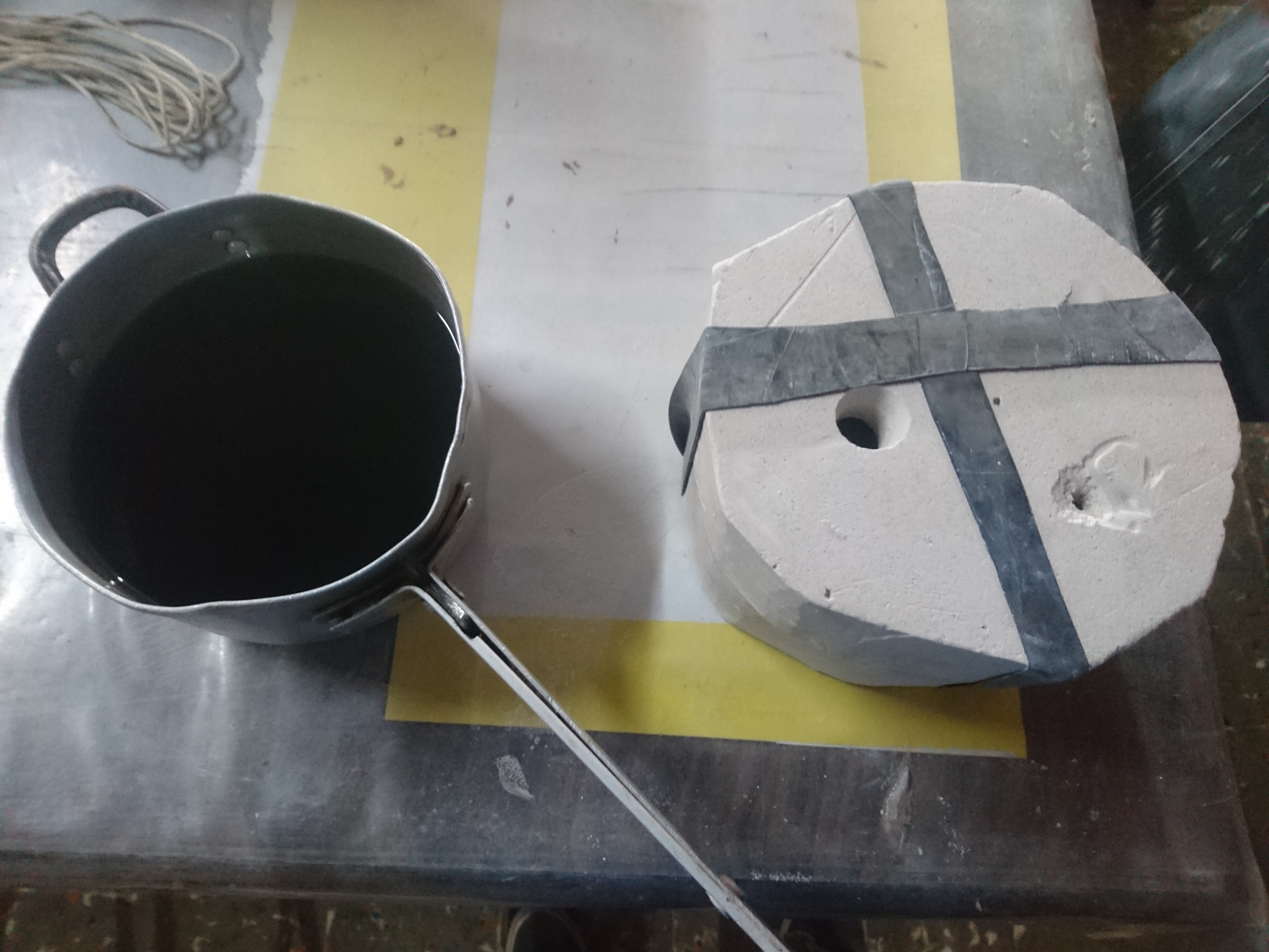
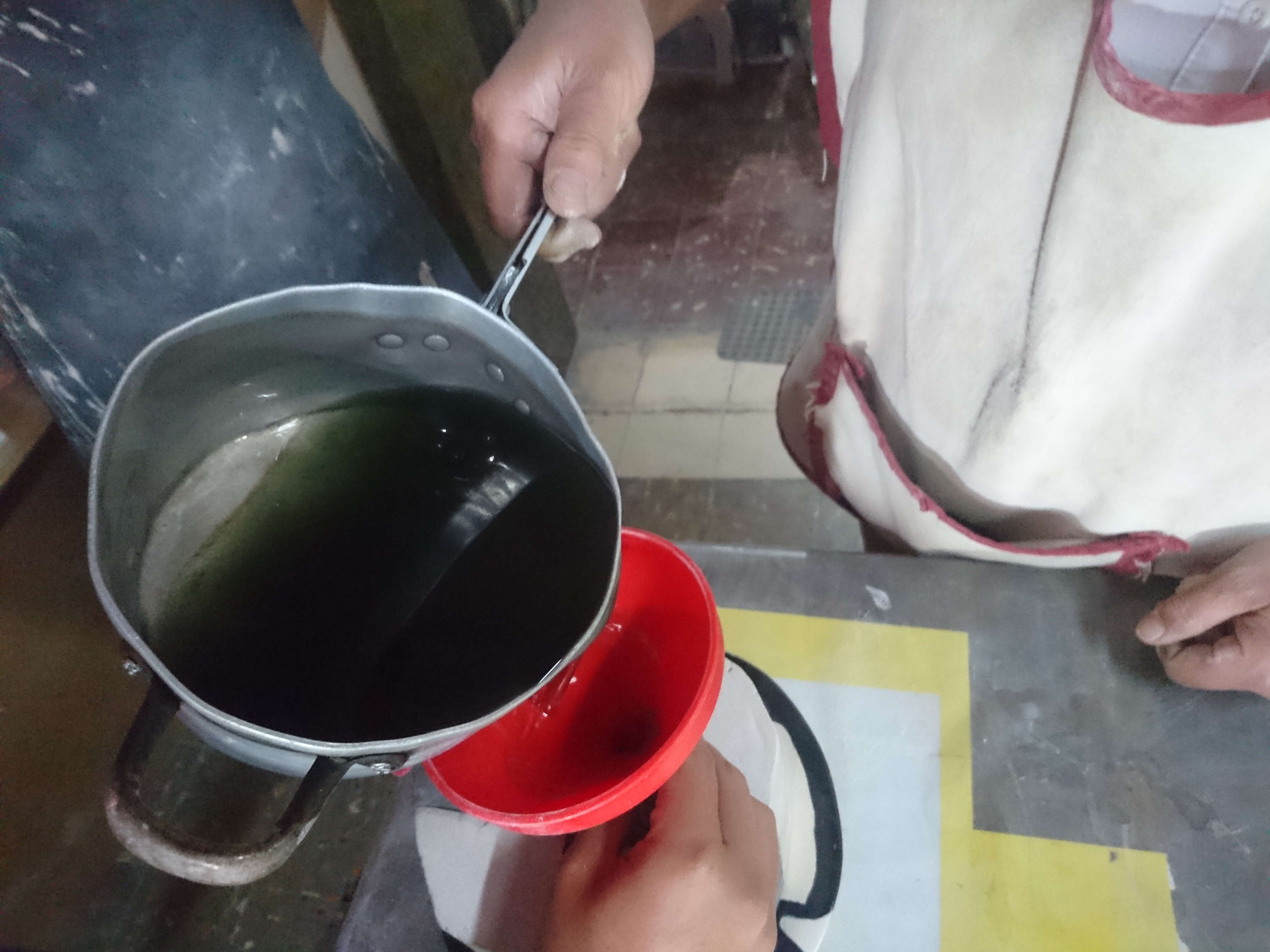
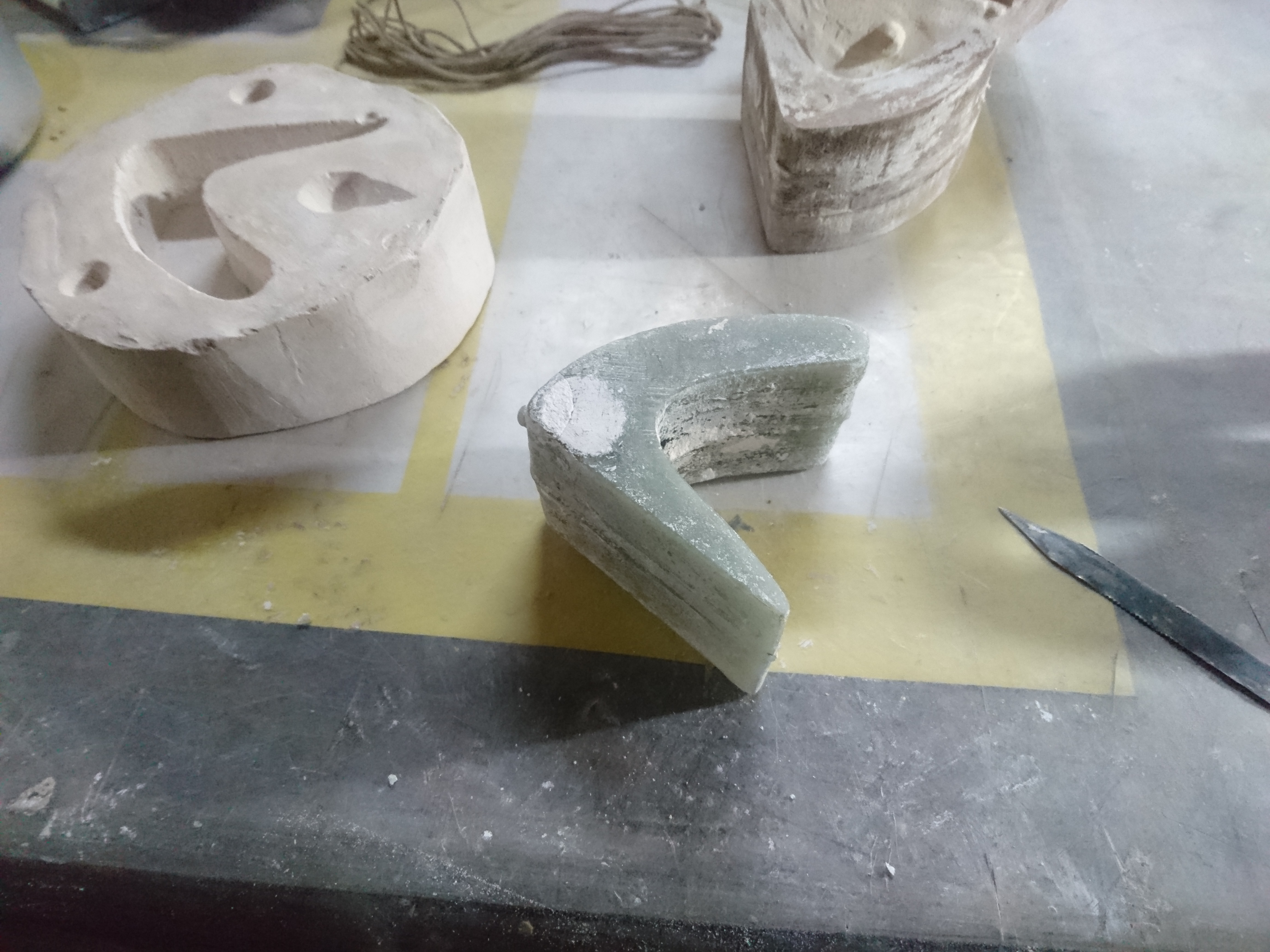
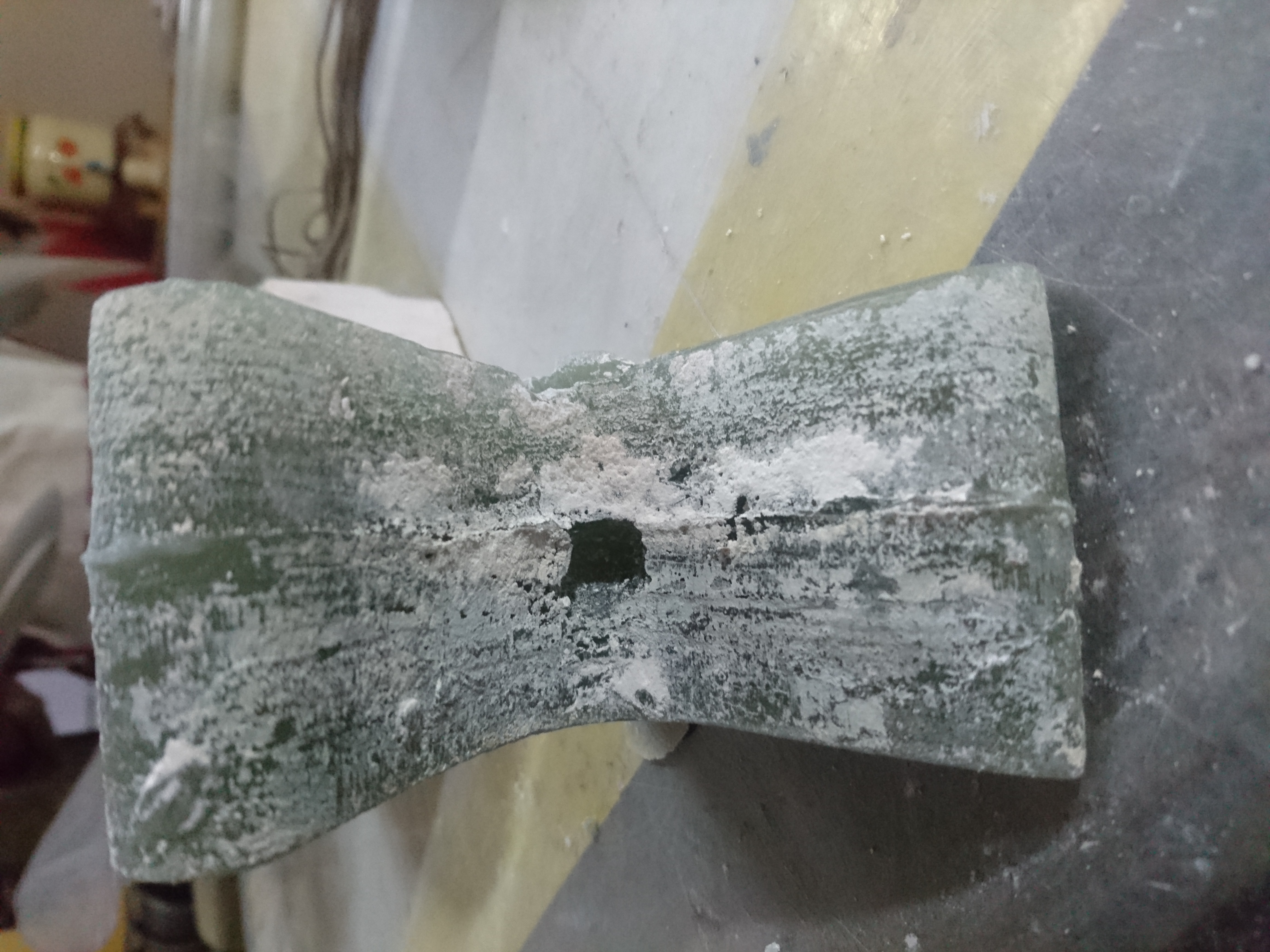
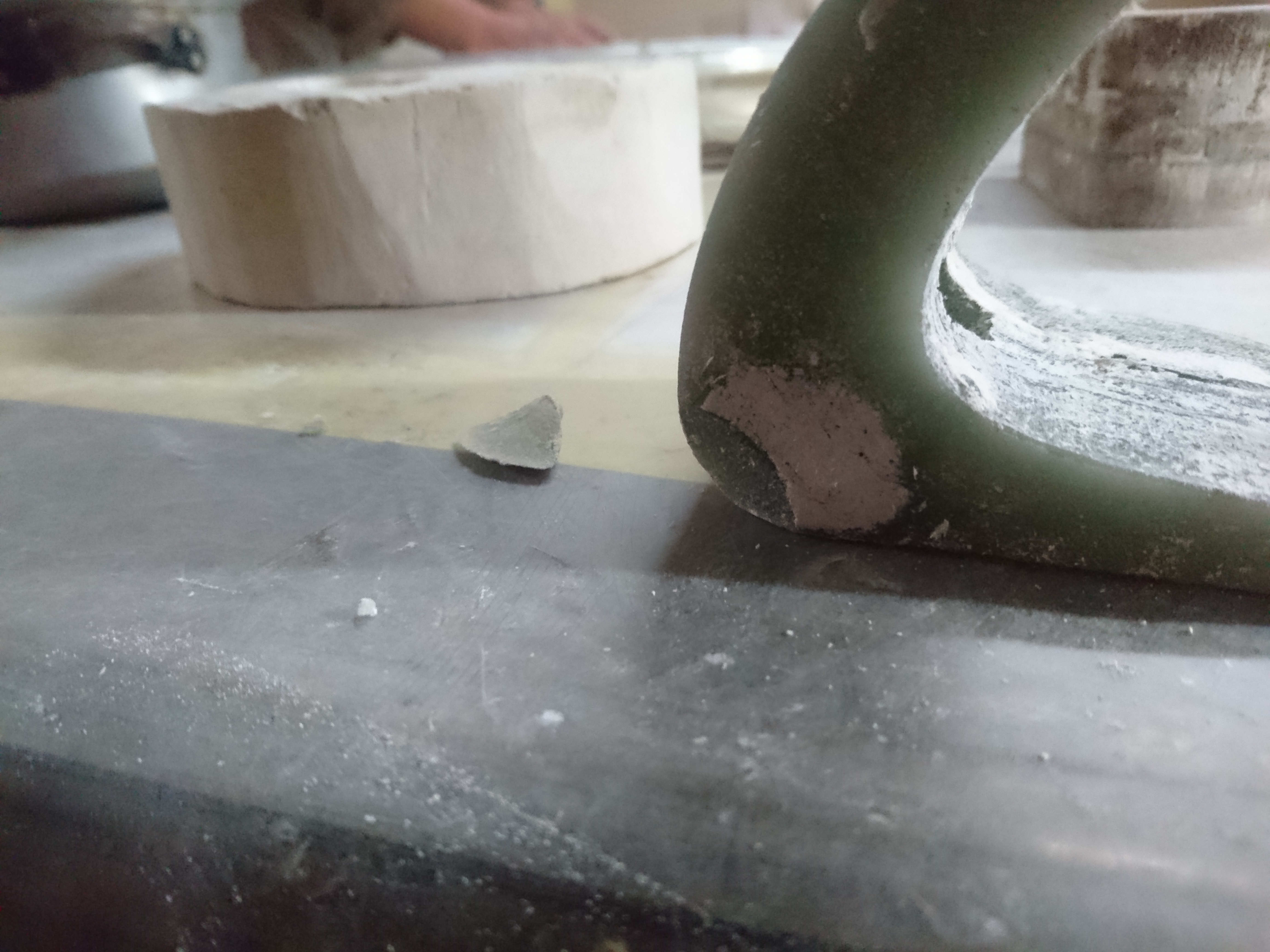
I use paraffin to fill the mold, pour it slowly so that it does not create a bubble inside the mold, wait an hour until it becomes hard and remove it from the mold, by a
bubble in the mold the lamp broke and another was created by filling and not filling completely.
solidworks
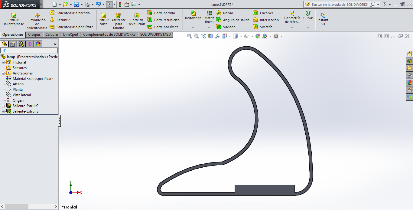
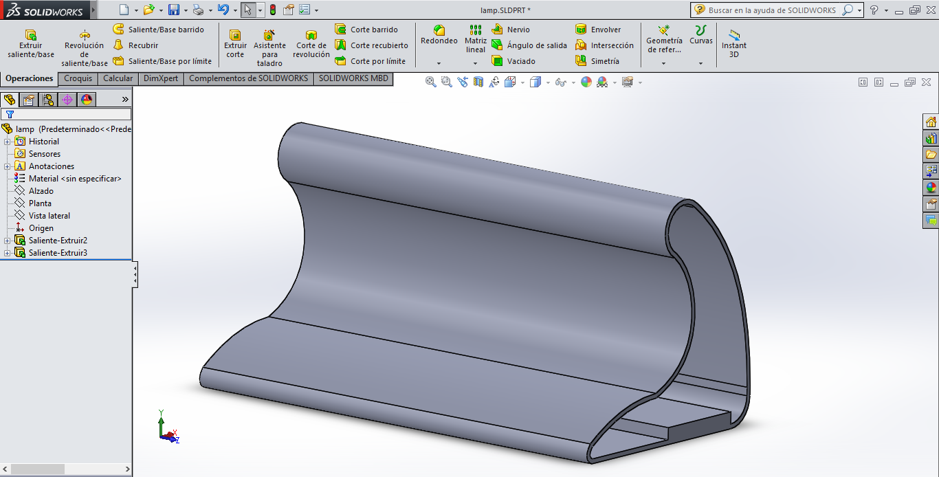
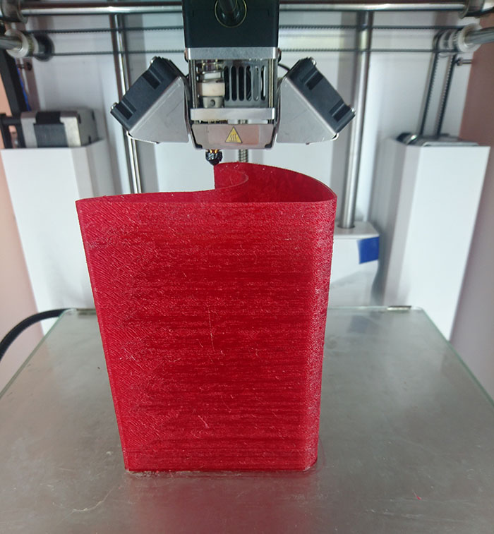
In this assignment to molding and casting I will do a lamp, first to begin I use solidworks to make a design for lamp,
my design is very simple but the objective is take the translucent of the rubber to illuminate.
In solidworks, I draw a plane contour firs then extrude at de measure desired, contour have a thickness of 2 mm for the printer 3D,
this measure change until to avoid wasting material when printing, is design for a lamp to study, was added a space for the battery.
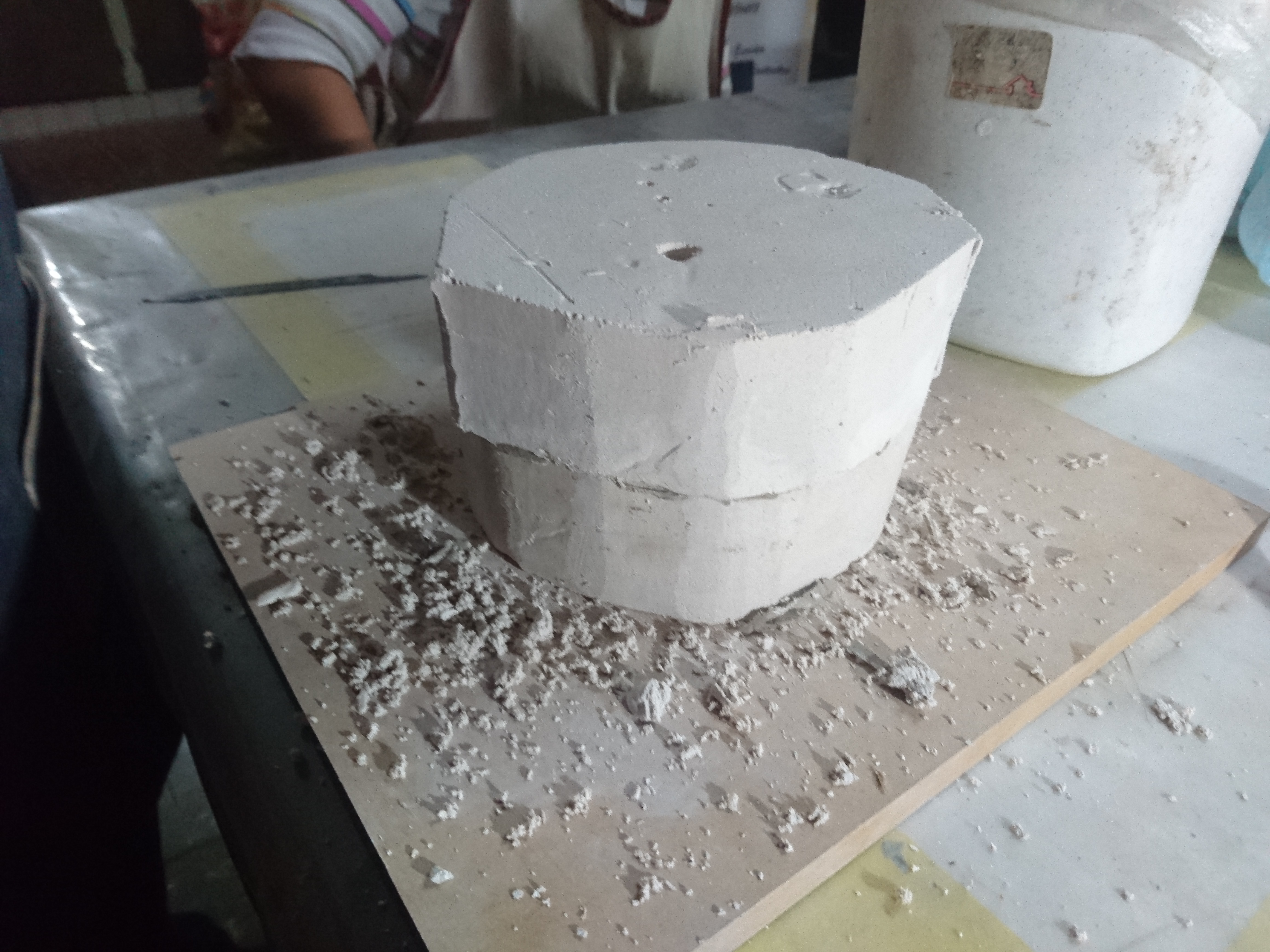
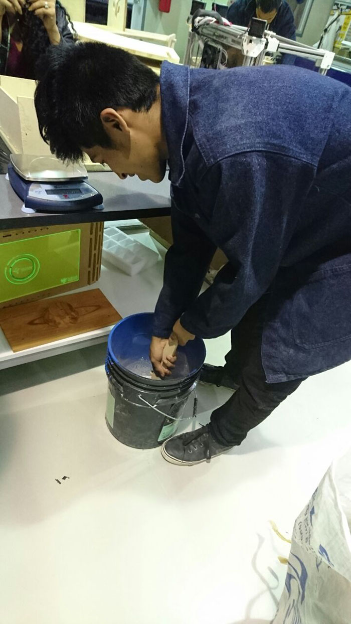
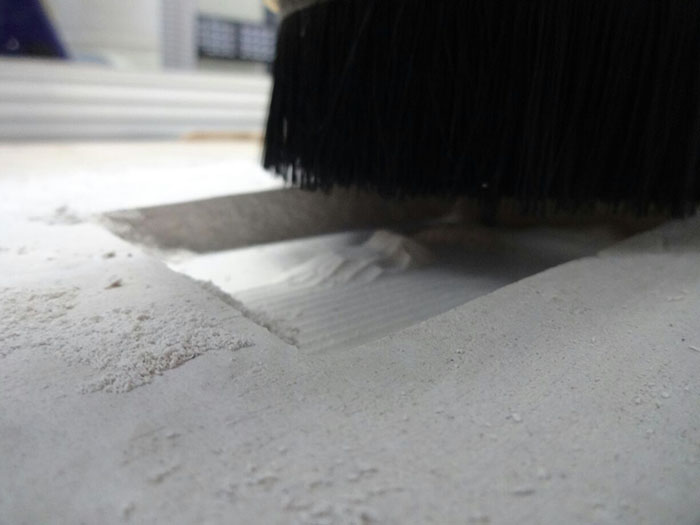
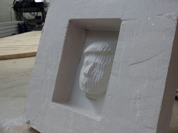
In this week we experiment whit plaster, the proportion to make plaster is 60% plaster and 40% water, first make a plaster blocks to after mechanize in shopbot CNC,
this experimentation is a first time in fab lab yachay and experimentation whit the mills available.
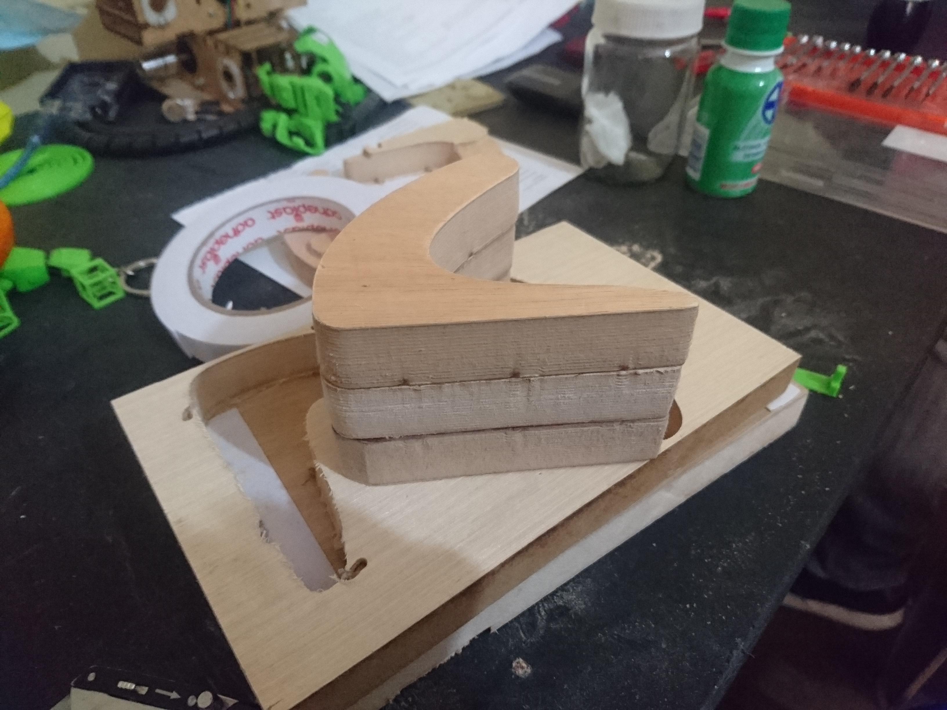
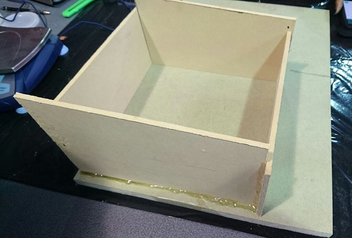
The mixture is poured in a “bed”, is five tables which form a square and the last collocated in the base,
the joints od the tables collocated hot silicon to the material does not leak, making sure of this we pour the plaster, do not forget to move a lot all the “bed” for all the bubbles go up.
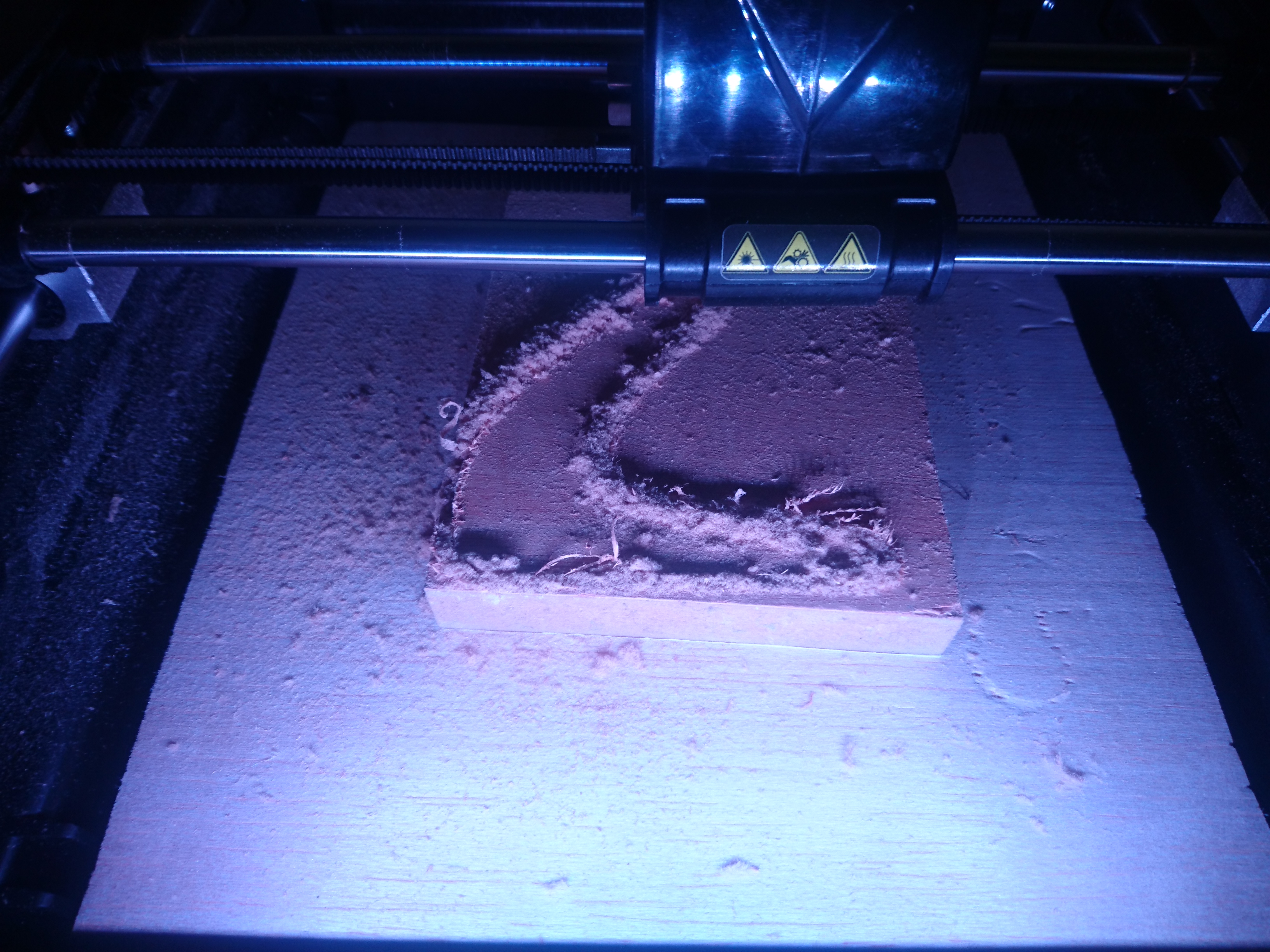
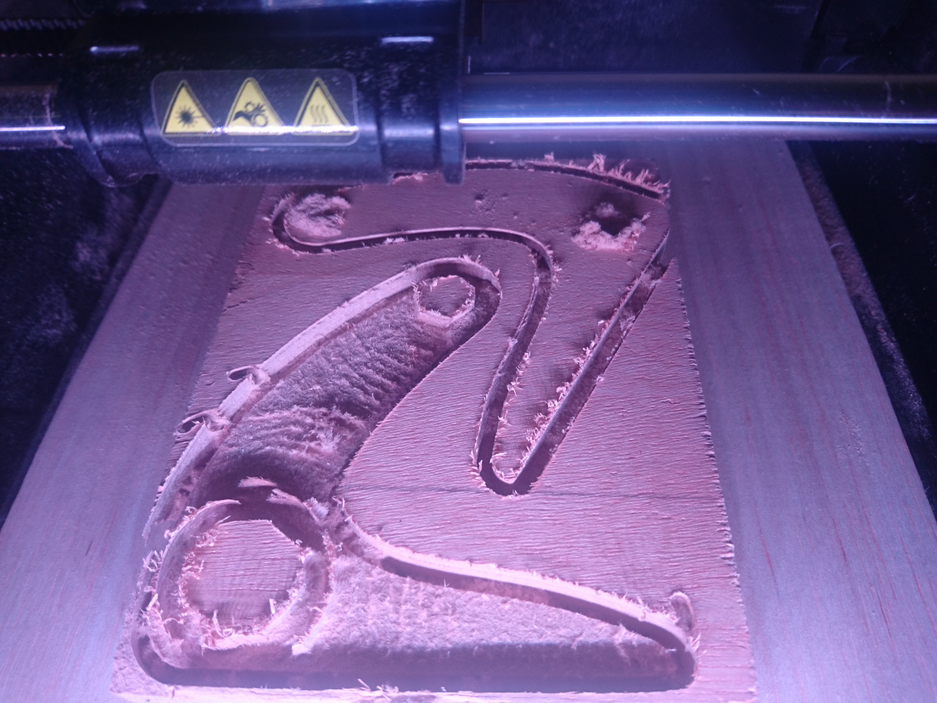
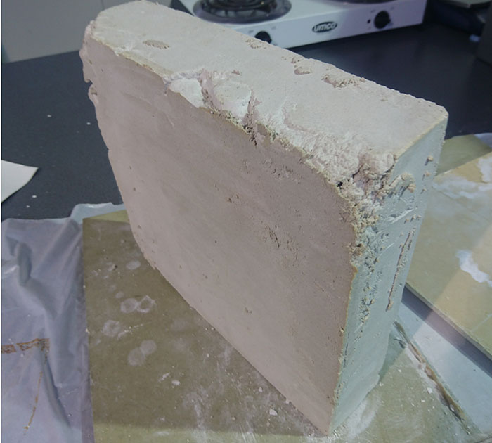
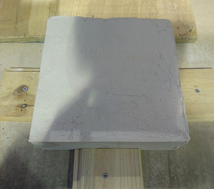
Before machining, wait a while for to dry, in our case wait three days, adjust the block to do not move when machining whit pieces of wood and screw and proceed to machining the block,
the first process is right but in the second the milling used it’s not the correct and the difference of diameter did not leave the correct finish.
If you need more information see the documentation on page: >>Angel Cuasqui<<
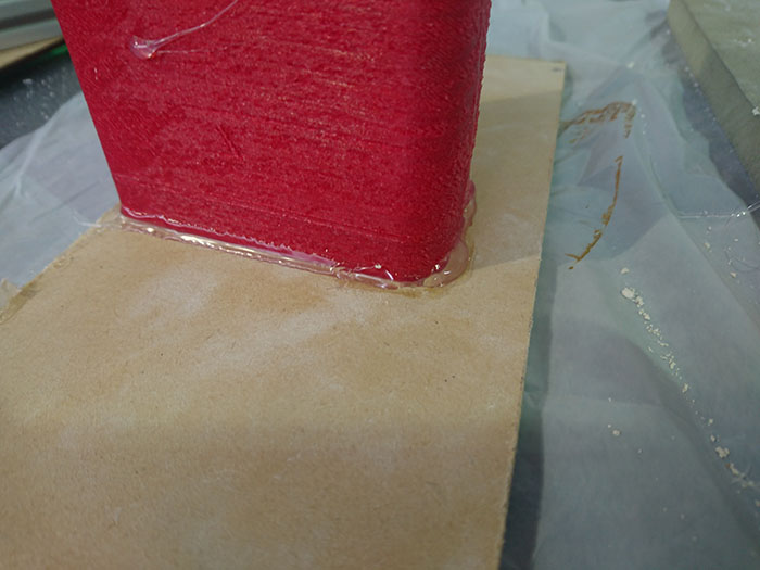
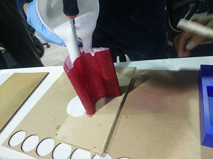
To my mold, I use a printing 3D to make a mold and taste with silicone mold, in the preparation to pour the material,
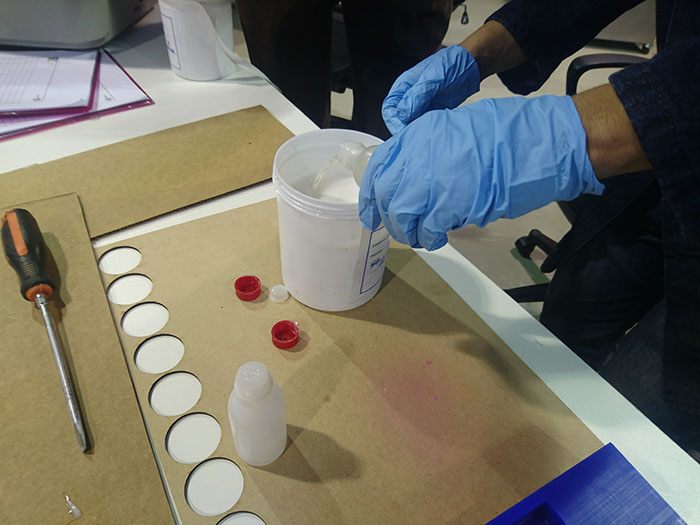
first seal in the base with hot silicon and the definition of print is not good, seal some holes, the mixing percentage recommended for maker is 100% silicon and 100% catalyst,
but in the test, is better use a 100% silicon and 25% catalyst because the reaction is slower and you can work best and more time to move for remove the bubbles.
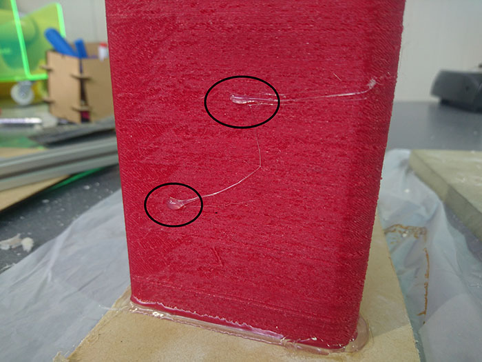
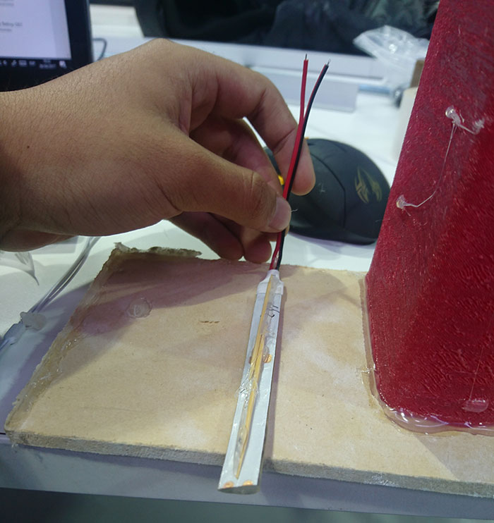
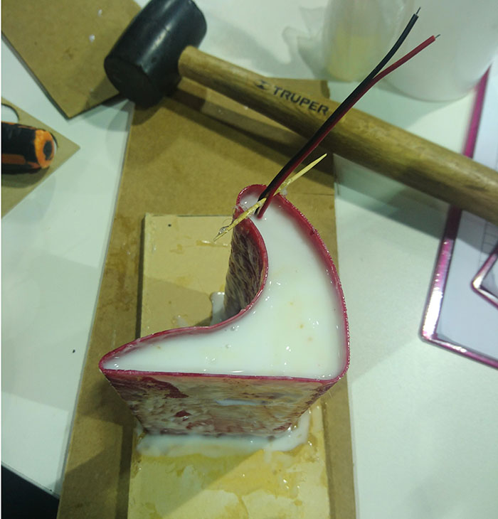
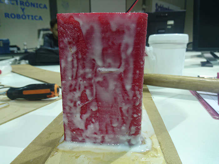
After pouring the material, the mold had a leak to print quality, for place LED strip into the lamp paste a toothpick to give it firmness, in the moment to pour the silicone in the mold,
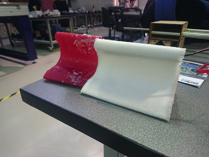
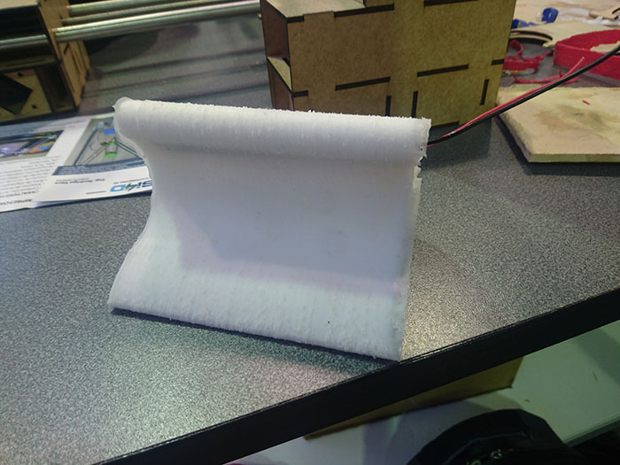
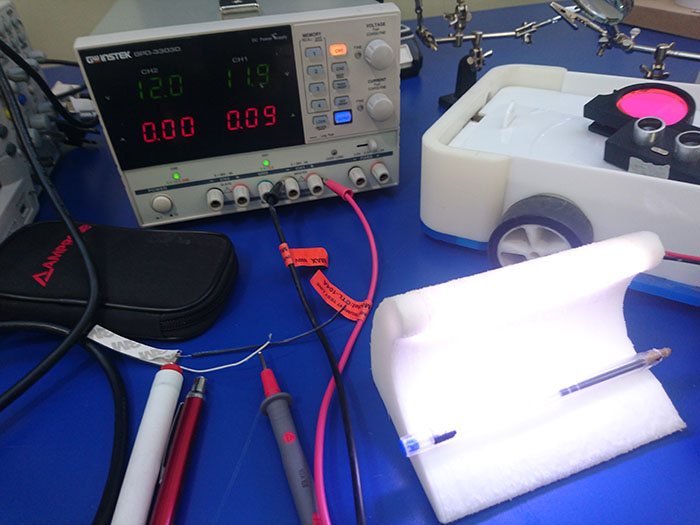
sink the LED strip and adjust with hot silicon to dry it, lasted all night to dry, in the next day to try extract of mold, by the thin of mold, it broke and reduced height, for finish with
a voltage generator taste the functioning of the lamp.
Learning outcomes:
- Design appropriate objects within the limitations of 3 axis machining.
For the milling make an experimentation with plaster and how And how do you react it you can see in the beginning of this assignment.
- Demonstrate workflows used in mold design, construction and casting
For the design for the mold I use a solidworks for make the piece to create the mold, the construction for is simple is made in 3D printer, for the liquid that I use silicon for make the
casting and this the process you can find in the middle of the page.
Have I:
- Explained how you made your files for machining
For the files use a parametric design and simple design in 2D to extrude it, the design is for can to enlarge at de measure of the user wants or depending on the height of the machine, a
recommendation is for the mold width because all the silicon trespass the wall I made, the design part of a rectangle and with the tool rounding the form is given.
- Shown how you made your mold and cast the parts
For cast the lamp remember before filling fill the mold with a release agent so that the silicone does not adhere to the walls of the mold and is easier to remove, the process is explained
in the process of the first objective.
- Described problems and how you fixed them.
The problem with the mold is the width because allows the passage of silicon through it, use a correct release agent because the silicon is adhesive.
- Included your design files and hero shot photos of the mould and the final object
Dwonload files
Files in Repo