Materials, tools and software
Roland (Tools)
Drill (Tools)
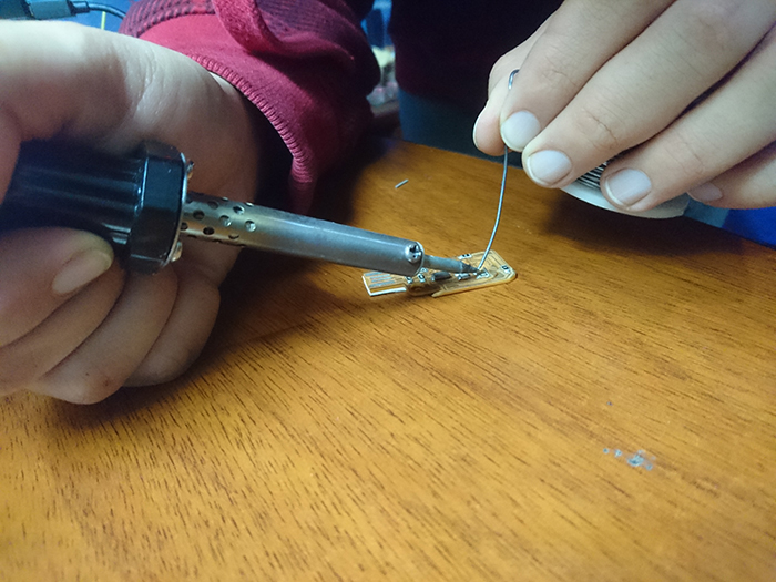
Soldering station (tools)
Tape (Tools)
Electronic components (Materials)
Copper Plaque (Materials)
Fab Modules (Software)
 |
 |
 |
 |
|---|
Roland (Tools)
Drill (Tools)
Soldering station (tools)
Tape (Tools)
Electronic components (Materials)
Copper Plaque (Materials)
Fab Modules (Software)
I select the Valentin board to make this assignment; this board is use as a programmer. At the end of the page, you can find the link for more information.
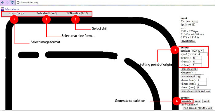
In the web page of fab module can modify the file to process in the machine. In the next image, you can see
all configuration and steps to make the image process.
Frist select the format and the image
Second select output format
Third select drill
Next Setting point origin
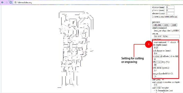
Next setting for cutting or engraving
To finish generate calculation
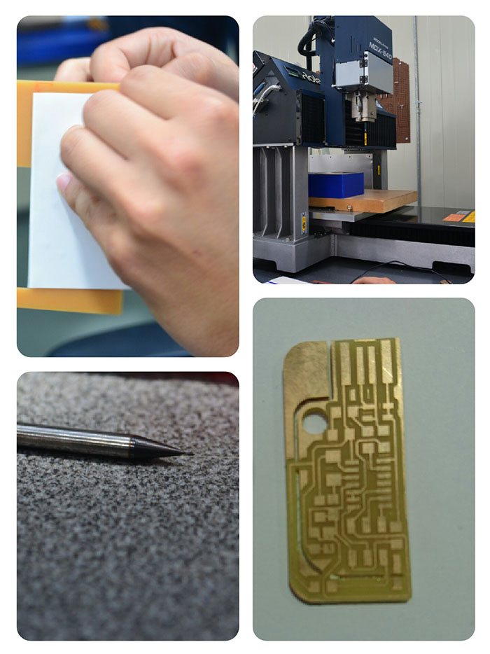
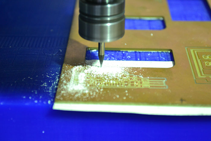
Before starting be sure you have the correct drill 1/64 (traces) or 1/32 (cut) and be sure that plaque fixed to the machine. Once secured. We begin the configuration go the machine starting with placing the starting point of the machine in "X" and "Y" (x=0, y=0) and setting z with the sensor that is connected because can damage the sensor, before to start cutting, verify all the parameters be correct and press "cut" to proceed.
2 Res 0Ohm
1 Cap 0.1uf
1 Res 10kOhm
1 Cap 18pf
1 Osc 20MHZ
1 Res 499Ohm
1 Res 1kOhm
1 Res 100Ohm
1 Attiny 44A
1 Zener-dioder
1 Header 2x3

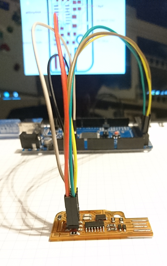
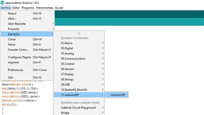
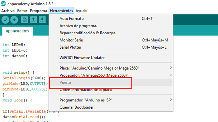
In order to program the board, you use a Mega Arduino which will be programmed as an ISP to select this library are chosen inside the library of examples as you can see in the image.
In order to program the board, you use a Mega Arduino which will be programmed as an ISP to select this library are chosen inside the library of examples as you can see in the image.
Download the following link in which we will find a software with which the file is loaded to the micro controller of the board.
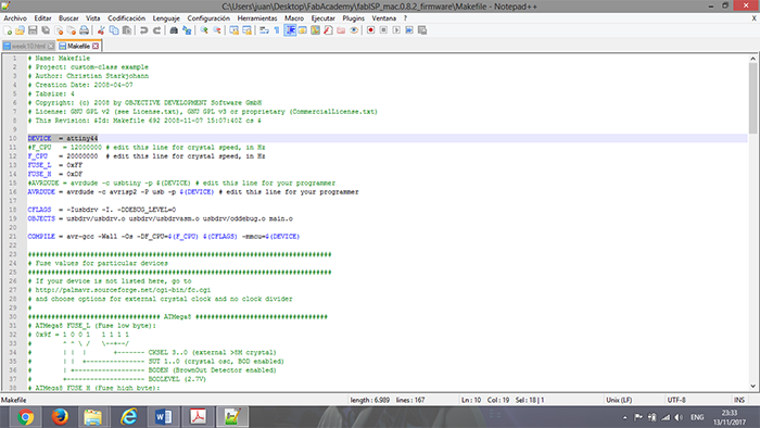
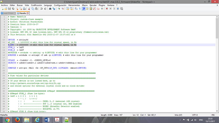
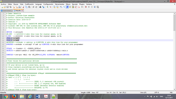
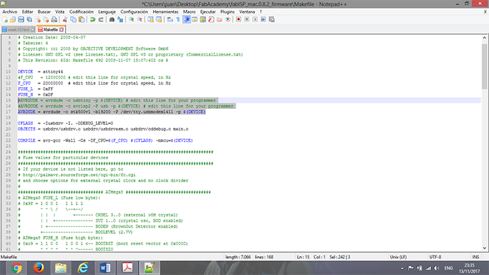
Open the file MAKE FILE with NOTEPAD ++ and edit the file.
We installed the program CYGWIN with which we created a simulation window.
In the program, we enter until locating the folder in which the FRIMWARE was saved.
To be able to locate in the folder we enter CD CYGDRIVE and the next step is to locate us in the direction of the file
Following is cleaned the files that are already generated with the command
MAKE CLEAN
Then the hexadecimal file is generated with the command.
MAKE HEX
Next, we compile the fuses.
MAKE FUSE
Finally, we programmed, we uploaded the Arduino file to the plate
MAKE PROGRAM
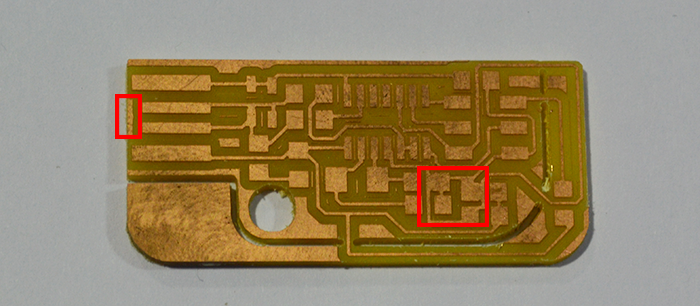
I had two small mistakes in developing the assignment.
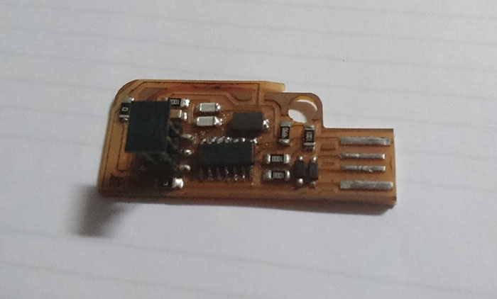
The first in the milling process, where some tracks were joined as can be seen in the following image. To solve with a blade the
affected areas are cut.
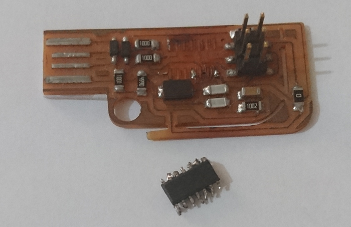
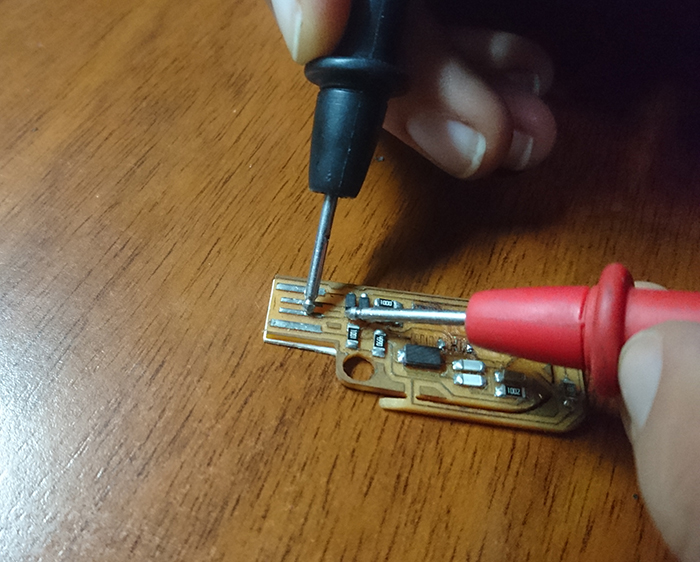
In addition, the second one found a damage on the microcontroller so it had to be replaced. In this way could be programmed without any problem.