In order to carry out the modeling, 360 fusion was used since this program can directly import the code of the machine in which the
file is machined.
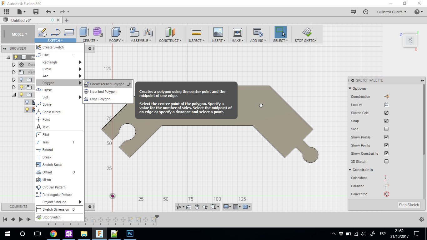
To model the chosen design, the polygon tool was used, in which its characteristics were modified to an eight-sided polygon with a diameter
of 300mm followed by a 40mm offset once the design was modified to fit the bed measurements having a capacity of 200 x 200mm so it was divided
into four equal parts machining two pieces at a time for this also designed a few lace assemblies between the pieces.
CAM PROCESS
Within the software allows us to directly generate the gcode with the calibration of the machine to which it is going to be used. For this,
the following processes were generated.
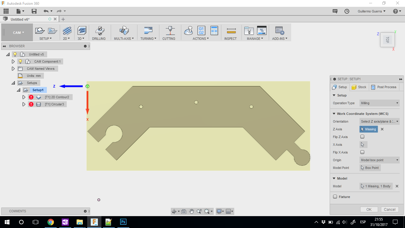
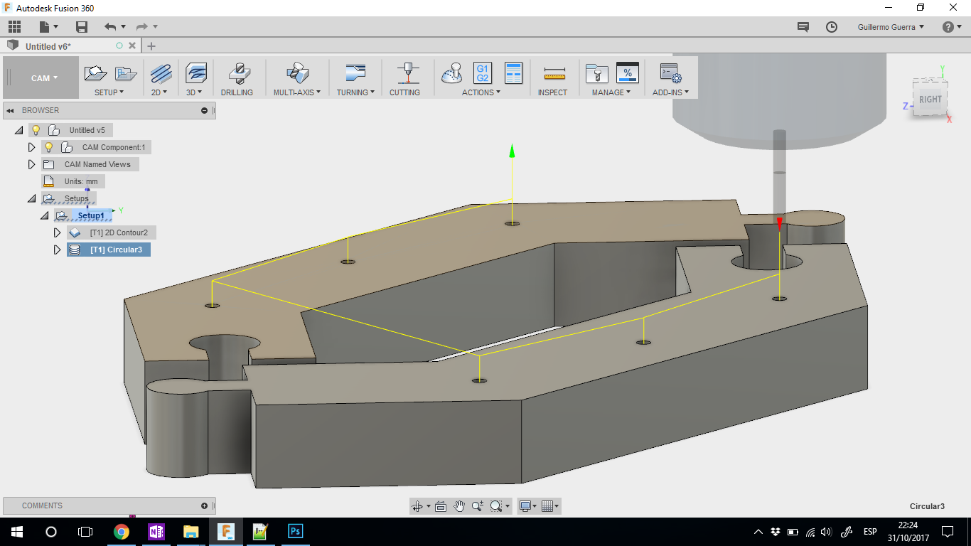
We chose the CAM process followed by creating a new configuration in SETUP in which we modified the frames of the pieces to be machined, choosing
the correct orientation of the axes according to the point of origin selected and that of the machine. To achieve this in the configuration, we
modify in the first two sales of the Setup menu orientations, axes and Stock in which the limits of the area to be machined are established.
As a next step we choose the process or the appropriate processes to be able to generate the form.
For the development of these pieces, two processes were used, each of which is detailed.
2D CONTOUR
Based on the design of the piece we chose the right tools for this the contour tool was chosen. In this process we also modify milling parameters
based on the characteristics of the milling cutter and the material.
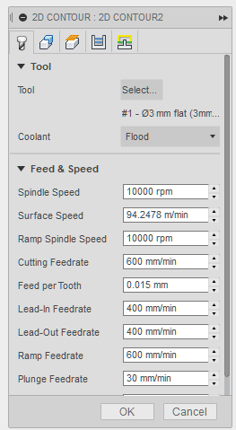
Tool._ in this window is configured and the mill is chosen according to the material for this process was chosen a 3mm titanium STRAWBERRY
with four blades, followed by this in the same window are set the speeds of step, rise, fall, etc.
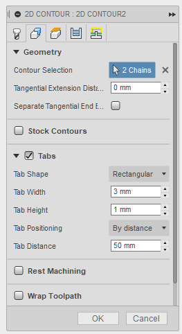
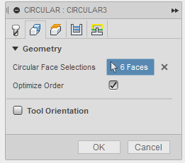
Geometry._ with this tool we select the contours of the pieces and add some couplings with which will hold the pieces so that they do not move
at the moment of finishing the cutting process to which they are attached at a prudent distance for this piece every 50mm.
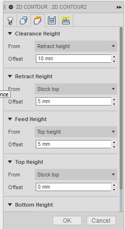
Heights._ No changes were made in this window.
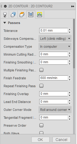
Passes._ With this tool we define the distance between the steps of descent, this will also depend on the type of STRAWBER that will be used
and the configuration of the speeds mentioned above for this process was determined a value of 2.5mm.
CYLINDER
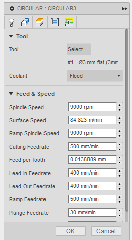
This tool is used to generate gaps with the same basic configurations of the previous process except for the speed since for this process it is
advisable to reduce the step speed and the spindle.
Tool._ Exactly as in the previous process we chose the different speeds for this process.
Geometry._ We select the cylinders to be processed.
The other configurations remain the same as the previous process.
Once all the aforementioned values have been established, we proceed to perform a simulation of the machining to check that everything is in order.
MACHINING
FABTOTUM is a multipurpose machine which allows printing in 3d, laser cutting and CNC machining these machines just arrived in the city for the
initiative of the Fab Lab project in the city of Cuenca to be able to publicize the main processes of manufacturing digital.
Taking advantage of the arrival of the same, the pieces were machined in this machine to check its operation. To be able to generate the file
these machines come with a complement for Fusion 360 with which it allows to save the files with the ready configurations for the machining process.
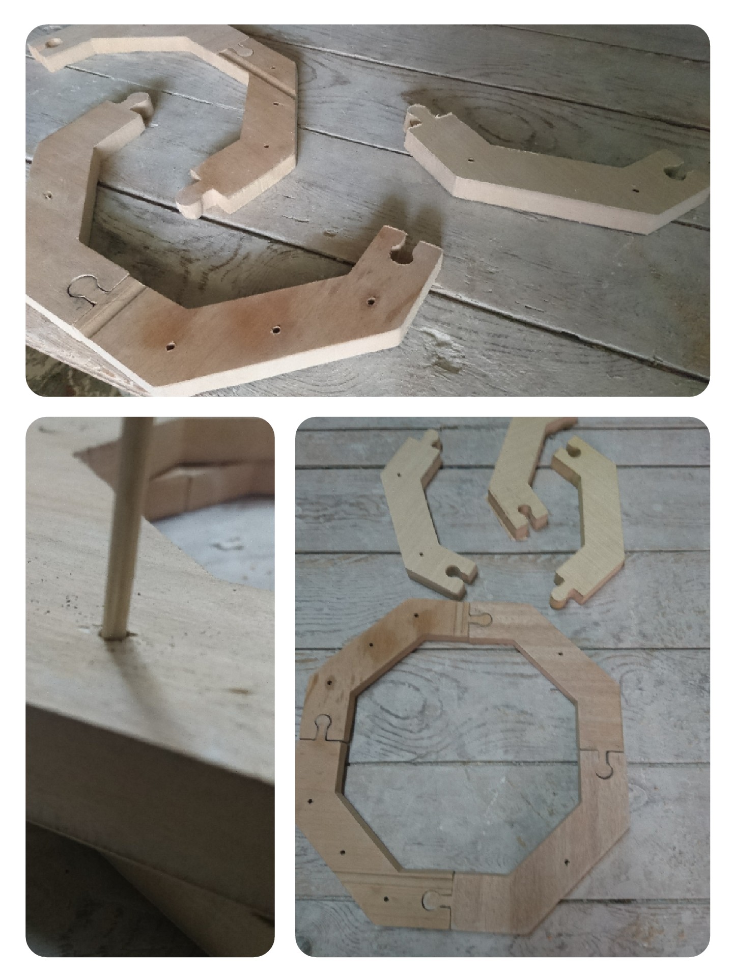
Was used MDF of 20mm to generate the mold which, with the help of a vacuum generation process, generates the final piece.
Assembly
As previously explained, the pieces were generated in parts, so they were assembled. 8 pieces were machined generating two levels which was placed
in the middle of the first plane by means of wooden couplings.
Composite
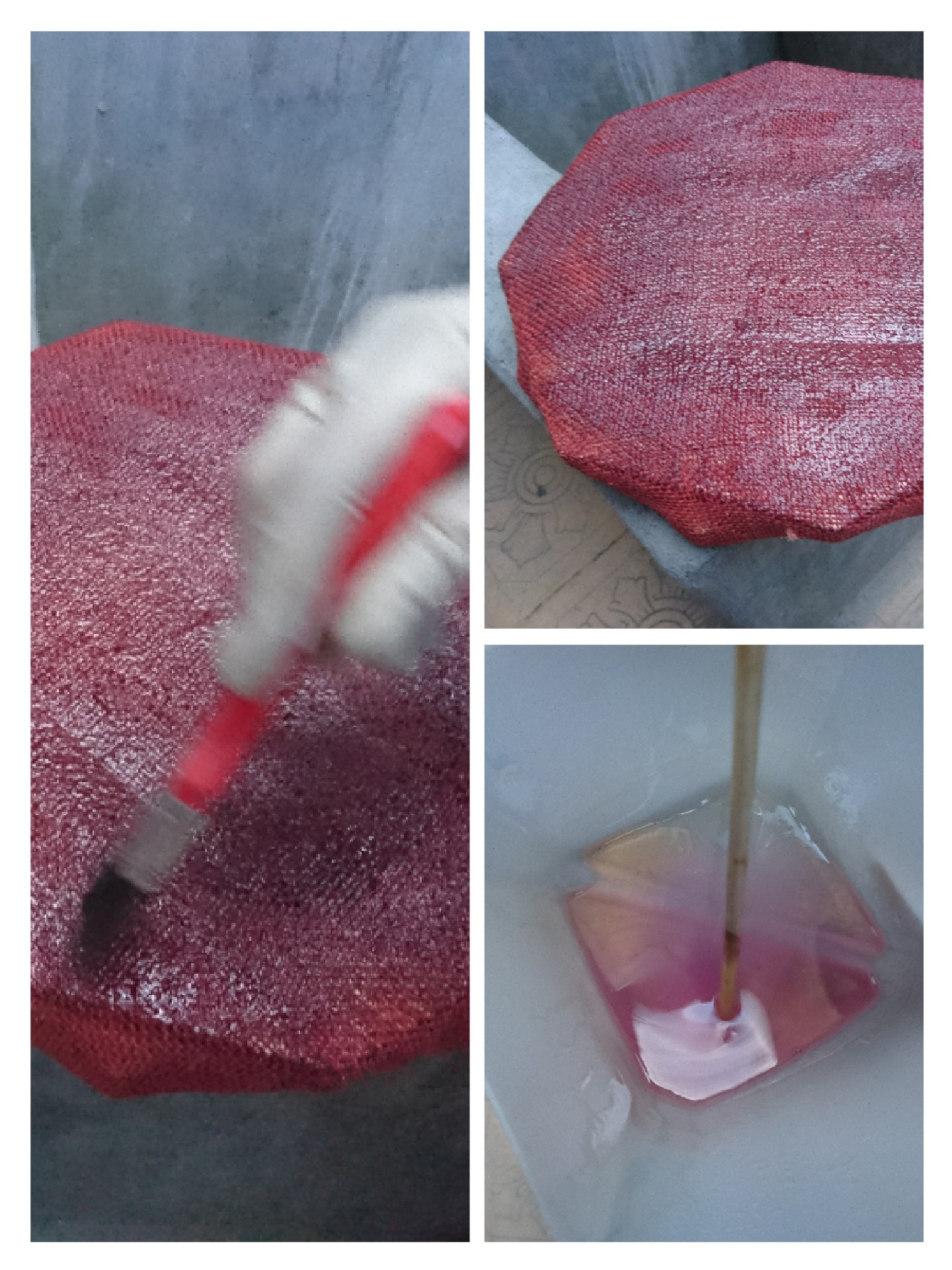
For this process Jute fiber was used a natural fiber extracted from a plant that bears the same name for more information attached a file in which
you can find a book with all the information about that fiber.
Which was linked with polyester resin which is also attached to the link at the bottom of the page. The material was subjected to the wood mold prior
to impregnation with resin, with a brush we covered all the structure of the piza resin that we need to generate the established design.
To generate the vacuum was covered with high density polycarbonate sealing leaving an opening to place in this case a vacuum cleaner covered with
fabric is placed to be damaged by absorbing resin this process is maintained until the resin takes effect in the fiber of jute.
PETT + Carbon fiber + Polyester resin
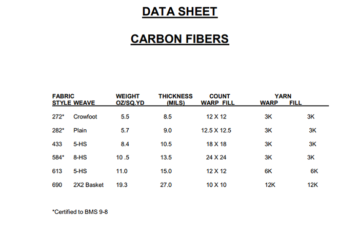
Read the material safety data sheet (MSDS) and technical data sheet (TDS) for the resins that you're using
To this assignments, I use Carbon fiber and Polyester resin to this I add the data sheet of two materials
Carbon Fiber
In the next link can take more information about different fibers materials and the carbon fiber
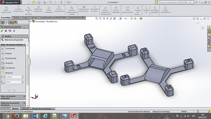
With this material, I design a Mini Drone structure (80mm) and printing them can use of structure for carbon fiber.
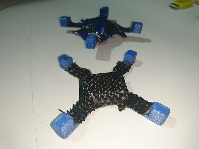
Production
For use Carbon fiber + polyester resin
Cut the Carbon fiver for the area the mold or a piece
Mix the resin with its catalyst (In the drying time, the amount of catalyst)
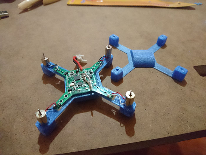
Then modeling and printing the chassis and cover to carbon fiber and the resin, finally put the electronics component.
This matirial are make in our workshop, next I put all dosage
-
-
-
-
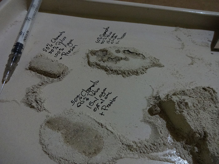
To this part experimented check the correct quantity to apply each one of them.
To ceramic dust, I take two different type states of material. The first is
the recollected of sand between take out the mold and the second of fail pieces
in the first burned. This combination add more structure of material.
Carboxymethylcellulose, Organic compound used as thickener.
To dilute it recommended leaving in water for 2 or 3 days.
You can see more information for this experimentation in my final project.
Learning outcomes
Demonstrate workflows used in mould design and construction
In the top you can see:
Frist, carbon fiber experimentation
Second, Ceramic Dust + Carboxymethylcellulose (Final project)
Select and apply suitable materials and processes to create a composite part.