This week was all about giving your designs a shape. 3d printing is turning out to be the fastest and the
cheapest way of rapid prototyping, there are instance where 3d printed objects are put to real use.
As a group assignment we were asked to lay down the design rules for our 3d printer and for individual assignment we were asked to get an object printed which could not be made subractively. We were also asked to try our hand with 3d scanning.
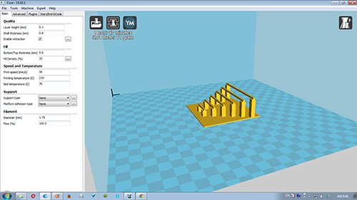
We have an Accucraft 3d printer at Vigyan Ashram, it uses Repeteier host as a machine software and Kisslicer as a slicer software. Other then this, we use Cura to roatate and orient the position of the object to be printed.
The process of printing is as follows.
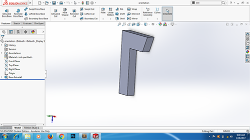
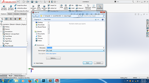
Saving the design file into .STL format.
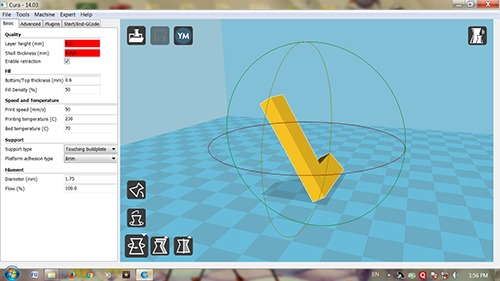
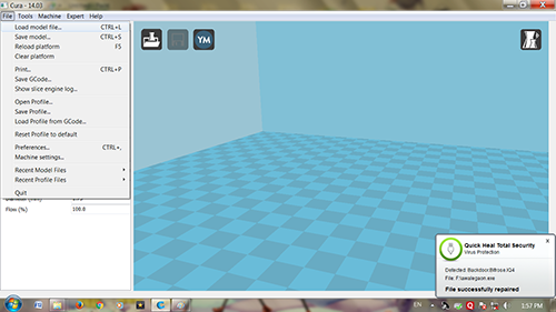
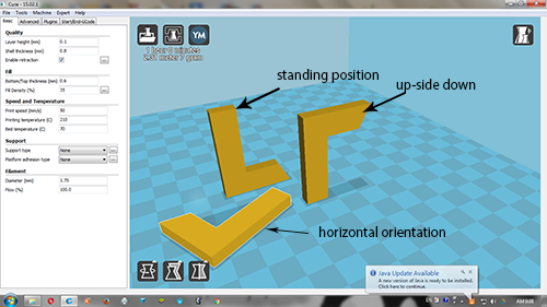
The slicer software we have does not have the provision to change the orientation of the object which will be printed, thus we have to import this file in Cura. Here we orient the object in the best possible way keeping in mind the fact that the orientation should result in minimum support. Save this file as .Stl
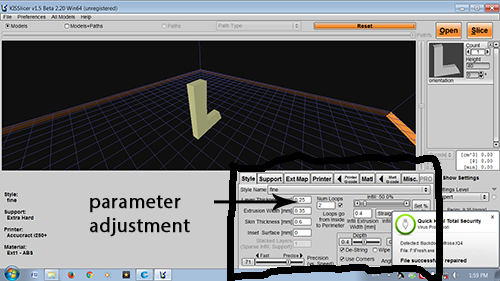
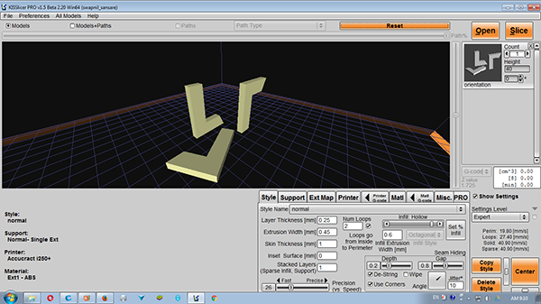
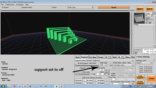
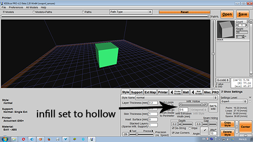
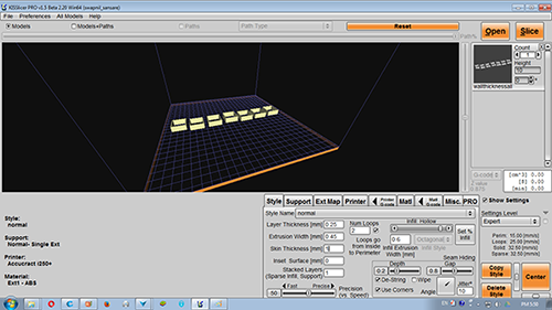
After this we have to open this file in Kisslicer,this is a slicing software where the 3d objec is sliced and a gcode is generated. Here we have the ability to set the parameters of our print such as supports, infill, skin thickness, layer thickness etc.
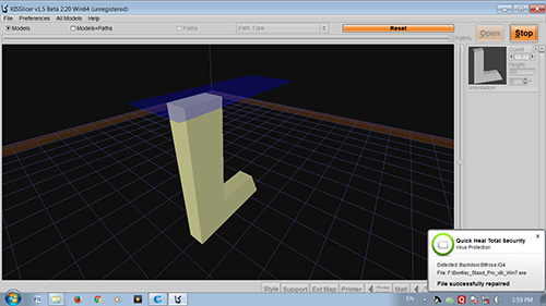
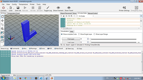
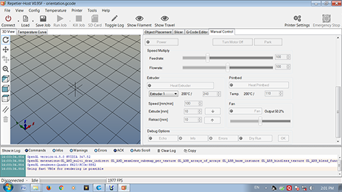
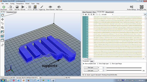
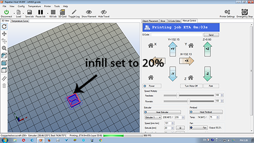
This gcode is the opened in the machine software, in our case Repeitier host. Here we control the machine, the bed temperature, ectruder temperature, pause/resumre the job, kill the job etc. It shows us how many layers are generated at the bottom strip, the status of printing in real time.
The possibilities and limitations of the 3d printer influences the final print of the object a lot thus we put our 3d printer through a lot of test to see its performance.
There are a lot of test files available online, these files have a lot of elements such as hole diameter, wall thickness included in them, I found them to be really intersting although we decided to test our 3d printer according to our tests. I would skip the part of designing the objects as these are very simple designs made in solidworks.
Here we tested a simple object by changing its orientation of printing. We checked the strength,the supports and the fininsh of the object.
Different orientation of the object
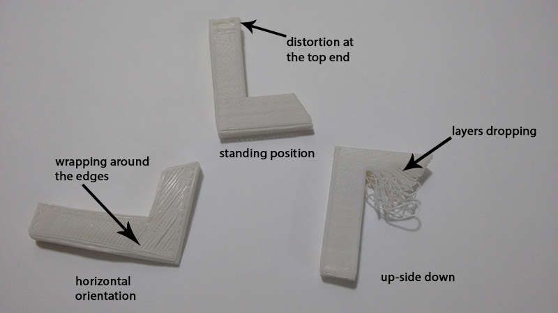
Observations - 1 - This orientation resulted in a best surface finish as smaller area was touching the bed although there is some distortion observed at the top surface, this might be because the narrow section bent under its own weight.
2 - This orientation resulted in total failure of the object, the overhang could not hold its weight and the layers fell down under its own weight.
3 - This is a stable job, although maximum area was sticking to the bed which resulted in a lot of wrapping around the edges.
In this test I made a parametric design and changed the angle of the overhang. We wanted to test at which angle the 3d printer can print overhang without supports.
Supports being created after an overhang angle of 25 degree
Observations - The printer could print without the support upto an an angle of 25 degree, after 25 degree it starts creating supports, this is an important observation as we have set a limit for the permisible overhang.
We have set the infill to hollow, the permissible overhang angle might change as we change the infill settings
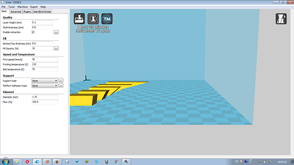
In this test we wanted to see the amount of sagging of the object when it is supported on its two ends.
The infill is set to hollow and the supports are set to OFF settings. We tested the object by varying the unsupportd lenght.
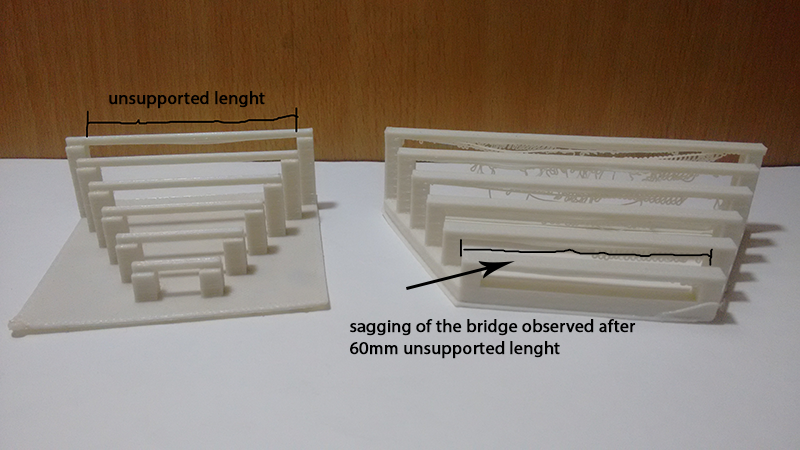
Unsupported lenght varying from 10mm to 100mm
Observations - The bridge could support its weight upto 60mm unsupported lenght, the bridge starts to sag and the layers tend to drop as we increase the lenght of sagging from there on. Thus we have set a limit for an unsupported lenght the 3d printer can print.
We have set the infill to hollow, the permissible unsupported lenght might change as we change the infill settings, this is obvious as the weight of the material will increase as we increase the infill.
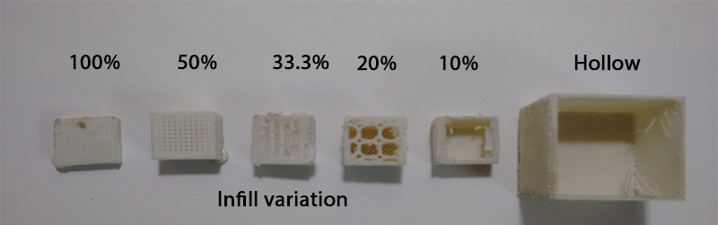
In this test we wanted to try out the strenght of various infills of 20mm*20mm cube. Slicer software lets us change the infills of the material.Skin thickness was also changes during the course.
Observations - The time of printing and amount of material required is majorly determined by the infill. For 20mm*20mm cube there was no major difference in the strenght. This might not be the case for a larger object.
The time of printing was to the longest for 100% infill, it took 17 mins to print 20mm*20mm*20mm cube, while it was 14 mins for 10% infill. The accuracy was set to 29 and skin thickness to 1mm in Slicer software.
The hollow cube was printed with 5mm skin thickness, it turned out to be quite strong and it took 29 mins for printing with the same settings.
Thus we have to play around and change the infill and skin thickness according to our requirement, I would personally prefer hollow sections with 2-3mm skin thickness rather than increasing the infills, this would save a lot of time, although the material required might not vary much.
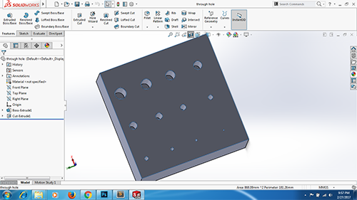
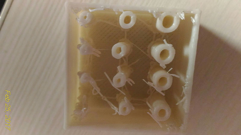
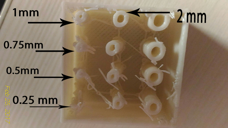
In this test we tested our 3d printer for its minium dimension that it can print. We made a cube having holes of various dimensions from 0.25mm to 3mm and printed it to set a limit to the minimum diameter of hole it can clearly print. The infill here was set to 0 and skin thickness to 1 mm.
Creating different diameter holes in designing software
Clear holes printed after 2mm diameter
Observations -
Although the manufacturer promises print accuracy of 80-150 microns, we observed that the printer was not able to print holes of 0.25mm diameter, it printed weak holes of 1.5mm diameter. The quality of print improved after the hole diameter was changed to 2mm and further.
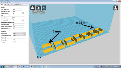
This test is similar to the previous test, here we tested our 3d printer for the smallest wall thickness it can print. The skin thickness was 1mm and the infill was set to 20%.
Wall thickness varying from 0.25mm to 2 mm
Observations - It can be seen in the image that the printer failed to print wall thickness from 0.25mm -0.75mm thick, some layer shift can also be seen in 1 mm thick wall. Wall thicknness of 2mm was clearly printed.
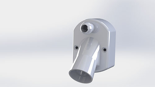
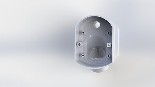
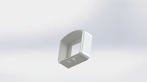
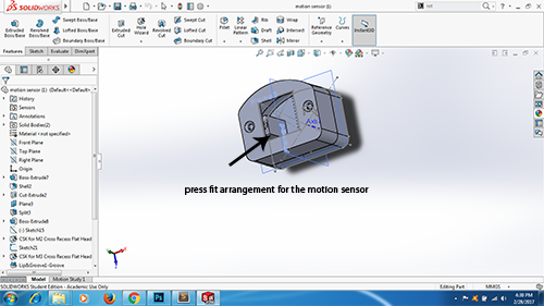
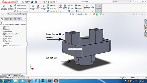
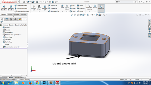
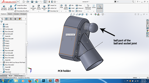
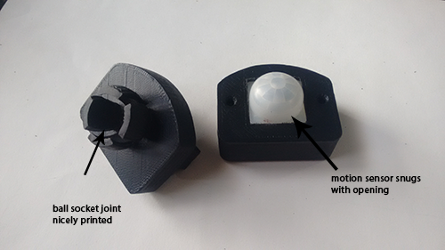
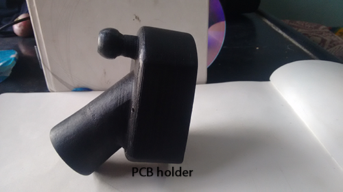
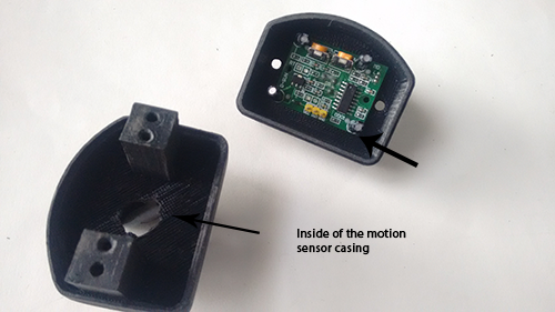
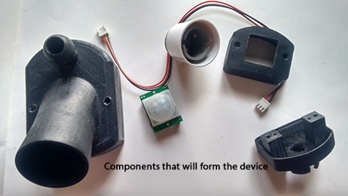
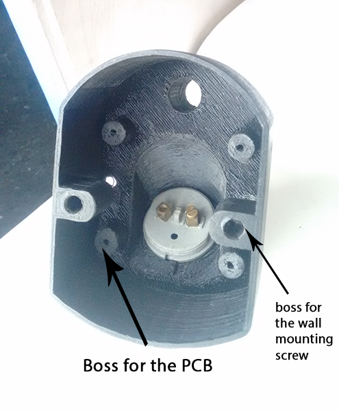
I am planning to do a motion sensing light switch, the device will be driven by the signals from motion sensors. I decided to do an enclosure for the same. The enclosure is divided into 2 parts, one will be the main PCB holder, this will also hold the bulb socket and the other part will be the where the motion sensor will sit.
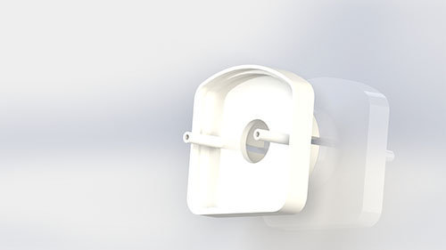
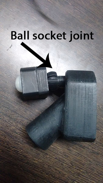
The two units will be have a ball socket joint between them which will allow the motion sensor casing to change angles.
I had already designed this object in week 2, I using the same files
Rendered image of the final design in solidworks
There were 3 different .STL files created.For the print the followig were the settings
skin thickness-0.75mm
infill- 33.3% (As the thickness of the device is 1.5mm and infill will have very little effect on the amount of maetrial and strenght.)
supports- grid type
accuracy- 75%( this results in very slow printing, it took me almost 13 hours to print all the three parts.)
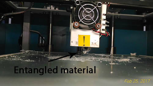
I faced a major problem at the very start of the printing, the extruder was not able to lay the materials in layer rather it was coiling the layer within iself.
I soon found out that it was making some knocking sound while it was doing it.
Trouble shooting
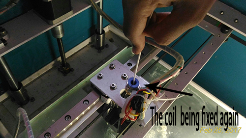
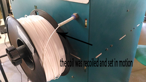
I doubted that there was a lot of strain in the pipe which goes from the ABS coil and the extruder head, the coil was recoiled and set free, now the printing was ok and we started from scratch.
It is really necessary for the first layer to stick to the bed, for this we normally use fewistick glue or a mix of waste abs and acetone
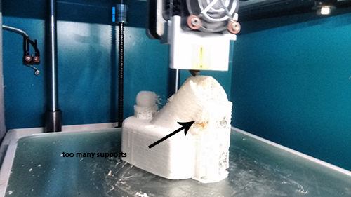
Now for the printing, there were a lot of supports made by the 3d printer, so post processing required a lot of efforts.
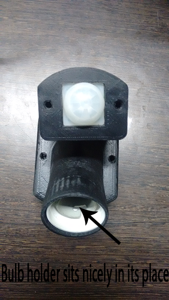
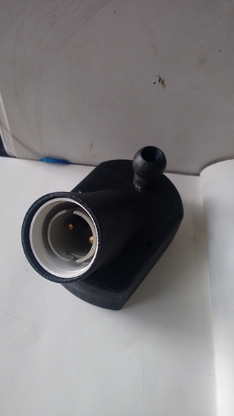
Although there were a few problems with the finish and the strenght of the product it worked well, it nicely receives the motion sensor and bulb holder.
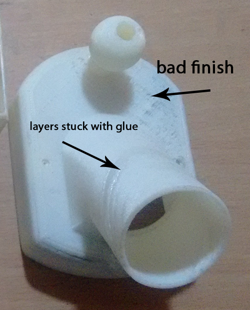
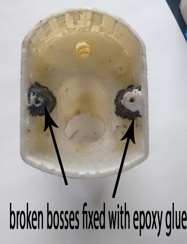
Although I was happpy with the working of the enclosure there were some problems with strenght and the finish of the enclosure.
The 3d printer we have is a basic level which cannot handle complex object easily over this it is a single extruder. A lot of damage is done to the object when its supports are removed and finished.
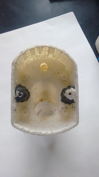
I wanted to see this object in a better shape one which could be put in our house. Thus I approached a commercial 3d printing company and got it printed.
The slicer settngs were a company secret, I only got to know that the infill was 20%.
Anyways I was happy with the product, the whole thing costed me 2700 Indian rupee
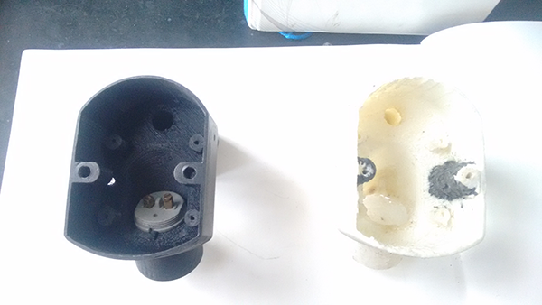
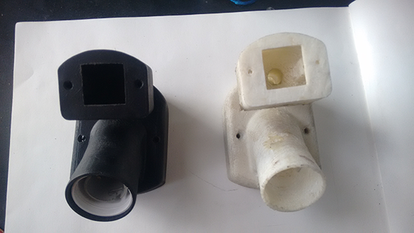
There is a clear diffrence between a commecially printed object and an object printed in a basic 3d printer.
Subtractive manufacturing is a process by which 3D objects are constructed by successively cutting material away from a solid block of material. Subtractive manufacturing can be done by manually cutting the material but is most typically done with a CNC Machine..... Google
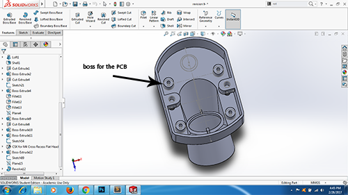
The object especially the PCB holder cannot be made subtractively because the bosses for the screws and the cavity for the PCB to rest on are in each other's way, thus to make the cavity a cnc machine will have to mill the bosses of the screw too, this is not recommended.
The motion sensor is a pretty simple design it might be done using a cnc but it makes sense to make it additively.
3d scanning is exactly the opposite of what we have been doing now, it involves scanning the 3d object and generating a mesh geometry of the scan. I did this task in two ways, 3d scanning using a 3D Sense machine and the other way is by taking a series of photographs and importing them in 123 D catch.
This process involves scanning the object with a hand held scanner. The scanner is connected to the PC throughout the process of scanning.
I first downloaded the installation file from the official website of 3D sense and then installed the software using a one time pass code
It is time to scan now, I saw a few tutorials on the web before beginning. The scanning needs diffused lighting and reequires you to be as stable as possible. 3D sense lets you scan person(full body/bust), objects(small, medium and large).
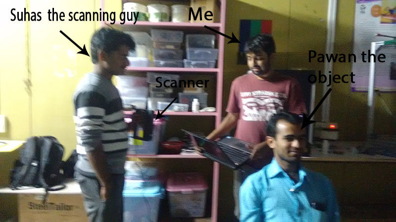
I decicded to scan my friend Pawan, I made him sit on a chair and scanned him for about 7-8 mins, making sure I am getting all the angles right. The problem was that the chord of the machine was short hence one had to roam around with the laptop in the hand I scanned.
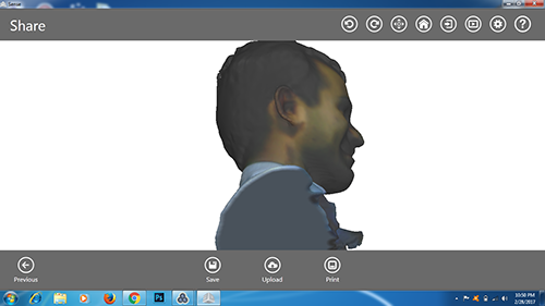
Then I followed the instructions of the given in the software, it basically lets you adjust the colour, contrast etc.
There is also an option to solidify or keep the object hollow, I chose to solidify the object.
Thus a solid model was generated in the software which we can save in .obj format.
Setup for scanning Output from 3D sense software
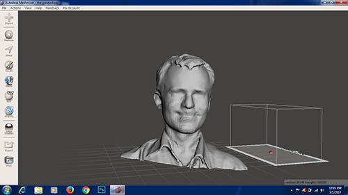
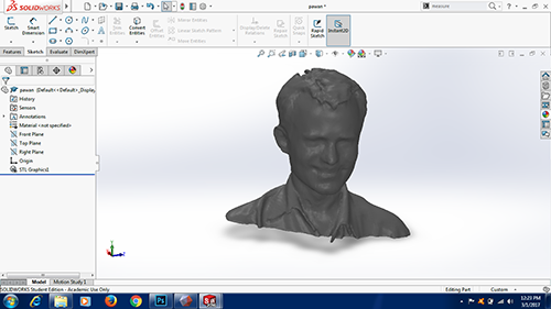
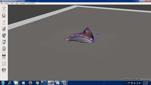
Then it is basically a matter of importing the mesh file in Autodesk meshmixer here yu can sculp the object, scale and repair the object.
I did not tinker around the software much, I made some basic chanegs and saved it as an .stl fileI imported this .stl file is solidworks gave it a plastic apeearence and rendered it.
This file is now ready to print
File editted in Meshmixer and Solidworks
The .stl file is almost 20mb in size even after resizing so I have uploaded it on the google drive, find the link here
This method is different from the one discribed above, this one does not require any special scanning device rather it needs us to take a series of photographs which when uploaded to 123 D catch generates a mesh file.
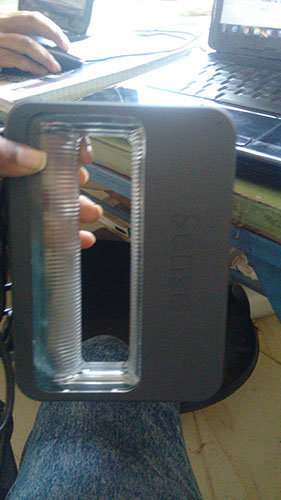
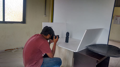
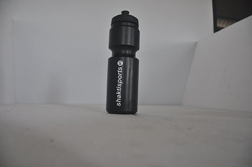
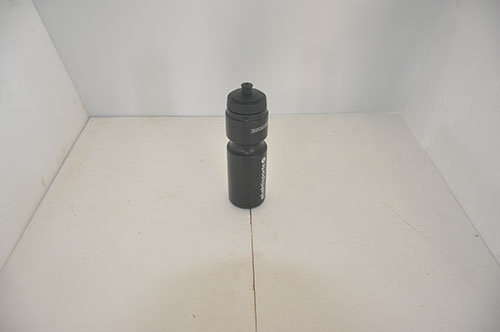
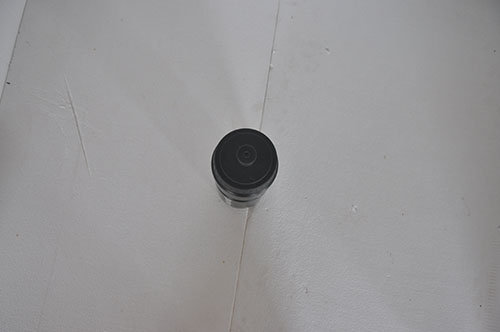
I followed some videos online and I started setting up the scene. This requires one to have a clean and clear background and have ample lights for photgraphs. I set the camera focal lenght to 18mm and took 15 low angle photos,20 photos of higher angle and a few photos of the top.
Set up and types of photos
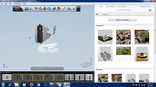
Then 123 D catch uploaded the photos and created a scene.
This process requires internet connection and takes a bit of time
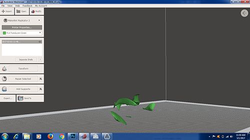
Some how my model was not generated, I could not figure out what the problem was, The software did not recognize any bottle in the picture, I am still going to try this method.
The image of bottle scene in 123 D catch
Bottle not generated when .obj file was importes in Meshmixer
My experience using the scanning tools
Overall I found scanning is not an precise method, I failed to generate model using 123D catch although I was able to do it using 3D sense machine.
3D sense is able to generate human faces upto a certain accuracy, this file can then be importes in MeshMixer, here sculpting and ditting can be done. This file can be saved as .STL or any other format for printing