Laser Cutting
Find the kerf and playing around with the power and speed
To simply put Kerf is the widht of the material cut by a machine, it is important because in order to get the perfect dimensions of object from a laser cutter we need to take into cosideration kerf every time.
I made a few test parts which I will cut using different speed and power settings.
I designed a 50mm*50 square in solid works and made cut it in laser cutter giving it different settings of power and speed.
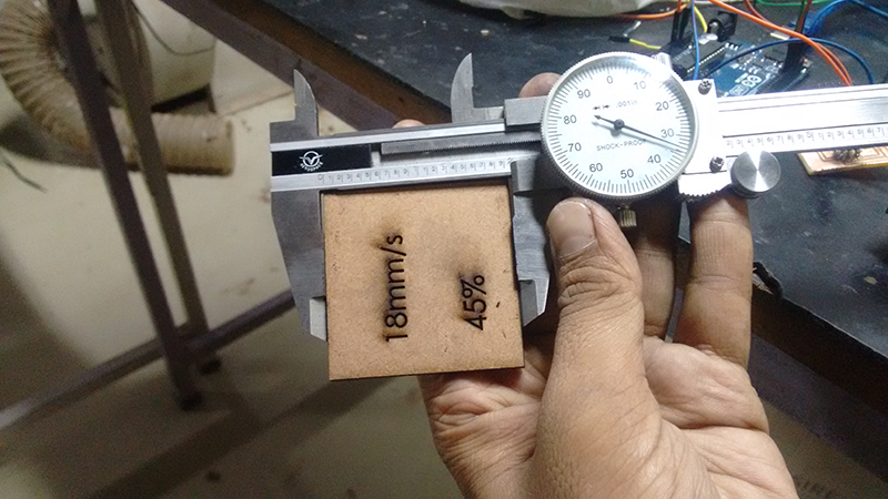
For one instance I kept the power same at 45% and varied the speed from 12mm/s -20mm/s and in another instance I kept the speed same at 12mm/s and varied the power from 45%- 70%.
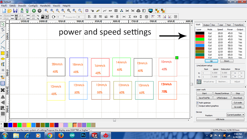
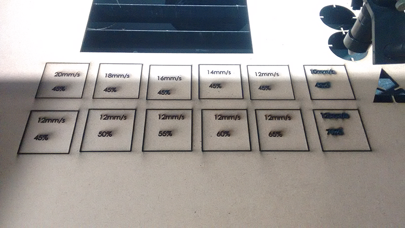
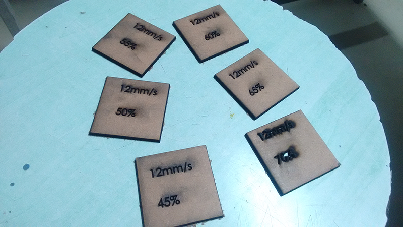
It can be clearly seen that as the power increases it starts to create black smog around the cut file, at 70% power the 3mm mdf almost fries up.
I personally would prefer the following setting speed 18mm/s -20mm/s and power 45% for 3mm MDF
Now I measure the width of the 50mm*50mm square, it came out to be 49.275, thus the kerf is 50-49.275=0.725mm. Thus if I want a perfect 50mm*50mm square I would have to compensate for the kerf and design a square of 50.725mm*50.725mm
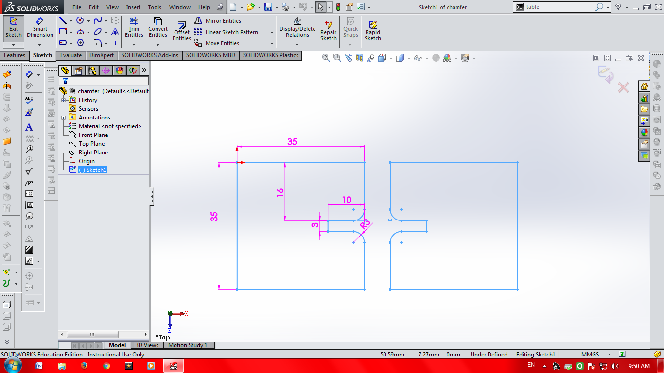
I have realised that solidworks is the ultimate tool for me, last week I came across most of its features this time I will be using its parametric funtions. Here I will create a skectch and define its dimensions as a function, I will change the dimensions of the sketch by changing the function value, this is really helpful if we have to make repeatative design of the same shapes with different dimensions.
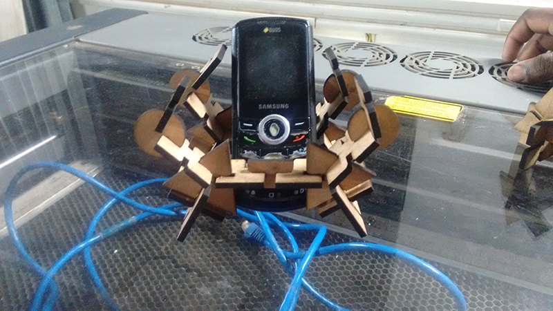
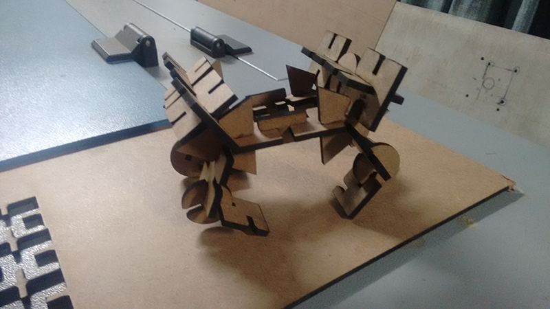
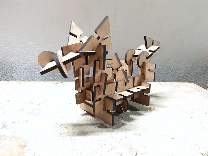
So I want to make a pressfir kit which could be assembled in many different ways , thus I am making a few shapes having slots on the edges which can be pressfit to the corresponding part in any way.
I start by drawing the sketches in solid wors and defining the dimensions
, Now to make define it I am inserting a design table from the
Insert tab in the tool bar
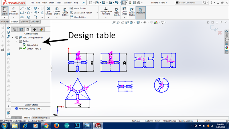
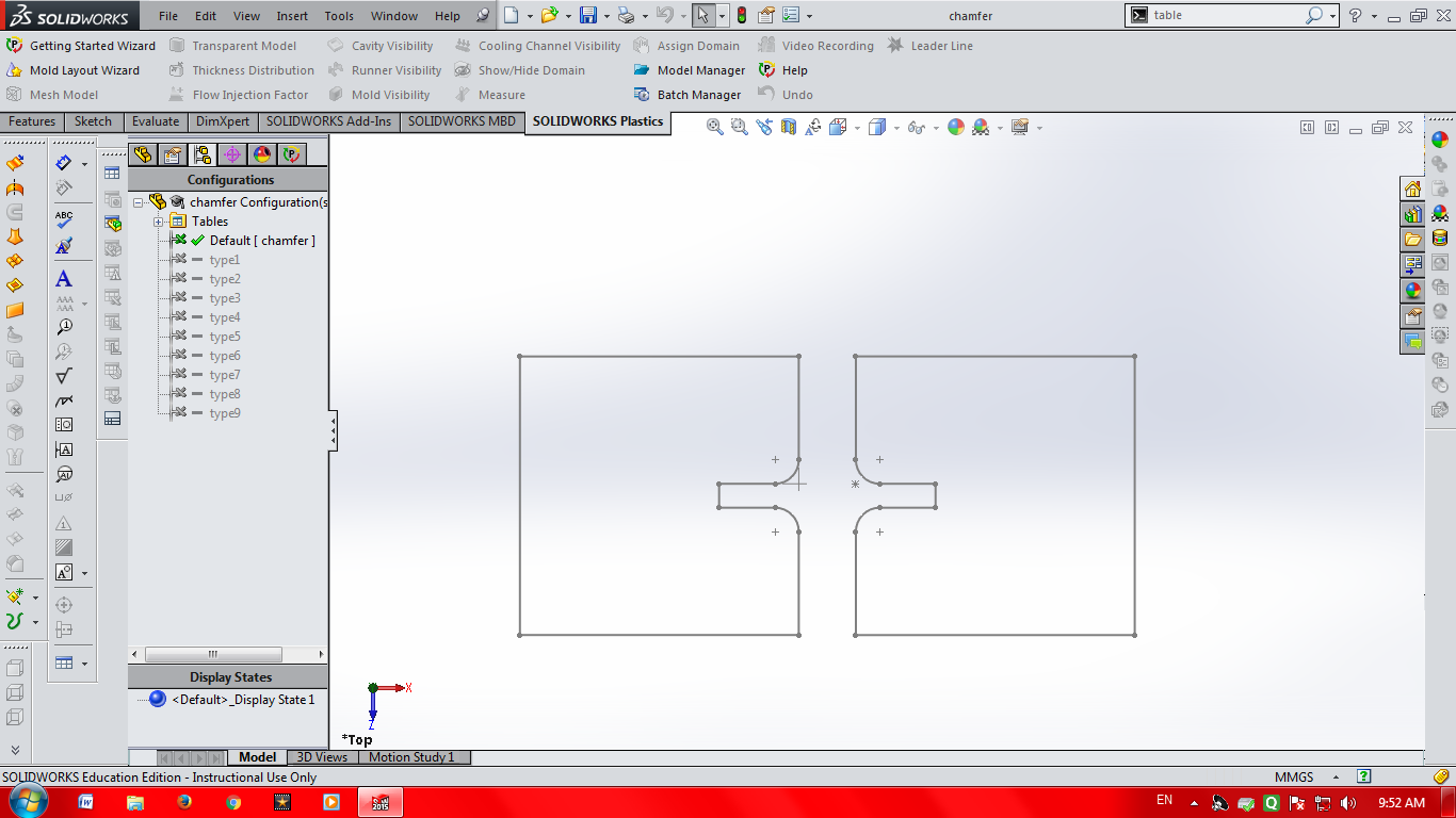
Note here that all the dimensions in pink colour are defined in the design table that means that if we change the value in the design table it will automatically update it in the design file
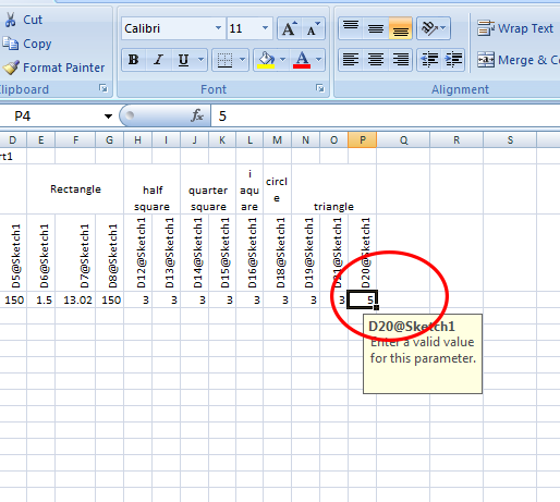
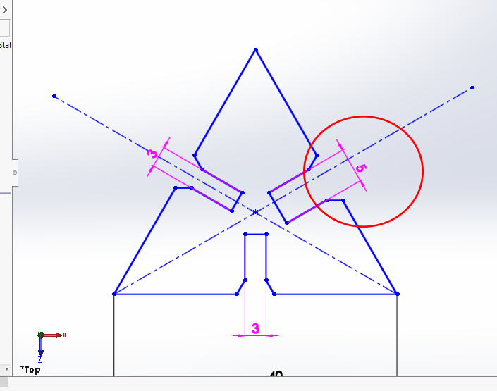 Changes done in the design table reflecting in the design file
The design table is a an Microsoft Excel sheet, so all the features that exists in the Microsoft Excel are included here, I make multiple copies if the same file if I add new values in the excel sheet.
I am really impressed with this feature, there a lot of tutorials of design table available on the internet, I do not have a specific tutorial to mention but Youtube could be a great place to start.
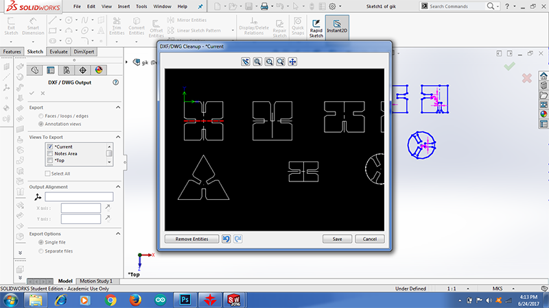
After everything is done there is one last thing to be done, to convert the files into dxf format, I saved the files in the dxf formar in solid works. Here I get an option to clean up the sketch in the dxf/dwg cleanup, this is a nice feature in solidworks as I get a chance to cleanup the dimension line or the construction lines that are there in the drawing
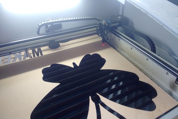
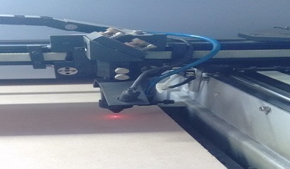
Now I move to the machine
About the Machine
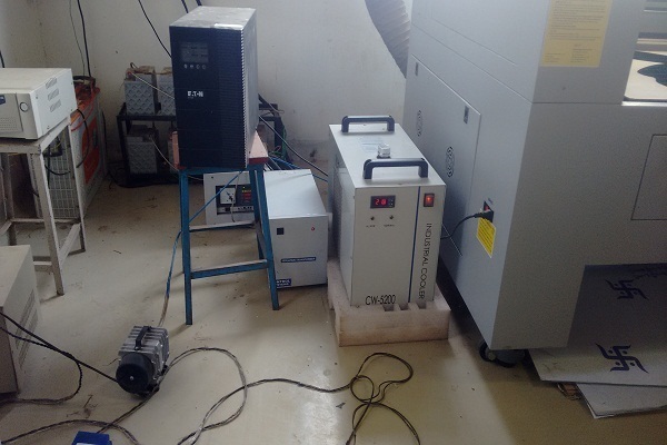
The Machine at Vigyan Ashram is SIL Laser Engraver. The bed size is 800mm*600mm and it can cut non conducting materials upto 6mm thickness
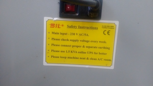
Precautions
As Neil said, Laser cutter is the most dangerous machine in the Fablab, thus one needs to take care of oneself and the machine before using it.
1 The machine at Vigyan Ashram runs on a three phase supply and it has proper earthing. There are frequent power cuts here thus the machine has a power backup.
2 The machine has air compresser attached to it and also an exhaust to expell out the dangerous gases out of the machine.
3 The machine has a glass lid to it which protects the user from the gases and also lets him see through it.
4 The chiller is required to maintain the temperature of the tube to an optimum level, in our case in between 20-22 degrees, thus we ensure that the machine be not used if the temperature is above 22 degrees.
5 The machine is also provide with an emergency switvh off button for any umprecedented situations.
6 Shiny, Glossy material should never be cut on a laser cutter.
Machine softwares and settings
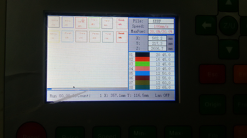
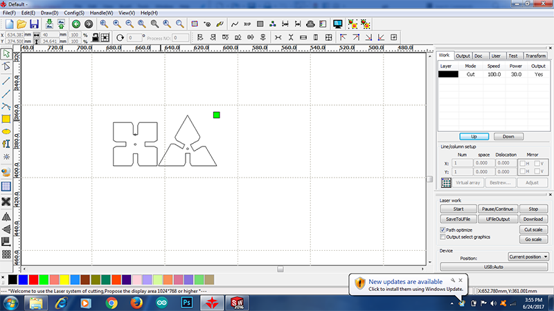
For our machine we have to use a machine software wherein we import our .dxf files and download it to the machine controller. We are using RD Works as a machine software.
Once you import the file in machine software we have can tweak have all the options ti tweak the designs here. Athough I dont prefer doing this I use this software to adjust the spacing between the cuts so that I achieve minimum wastage.
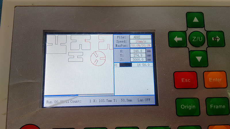
Once the cutting layout is made we have to specify the cut speed and maximum power for the laser.
My instrucror asked me to try the following settings
For MDF sheet(3mm thick)- speed= 18mm/s, max power=min power=55%,
For MDF sheet (6mm thick)- speed= 12mm/s, max power=min power=70%,
For Acryllic sheet (3mm thick)- speed= 15mm/s, max power=min power=60%,
For MDF sheet (6mm thick)- speed= 12mm/s, max power=min power=77%,
For Cardboard sheet (6mm thick)- speed= 18mm/s, max power=min power=50%,
We are using RD Works as a machine software
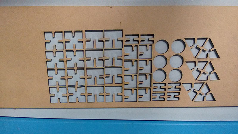
I will first try a test part before giving the final print, I place the two parts as close to each other as possible to save the material.
My first trails were with 16mm/s speed and 50% power
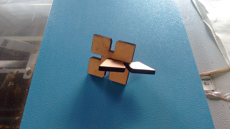
I realised that the joint is perfect the 3mm width of gap I maintained in the solidworks software is perfect for my design.
Also there was a lot of black dust around the cut object, I had to reduce the power and increase the speed
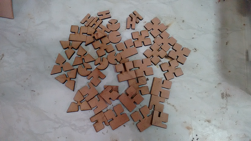
I placed all the objects as close to each other as possible in RD works and gave aprint, this time I am using 20mm/s speed and 45% power.
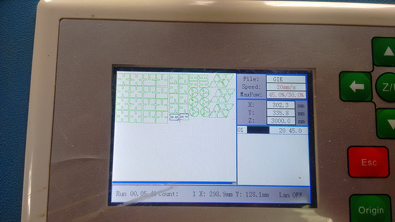
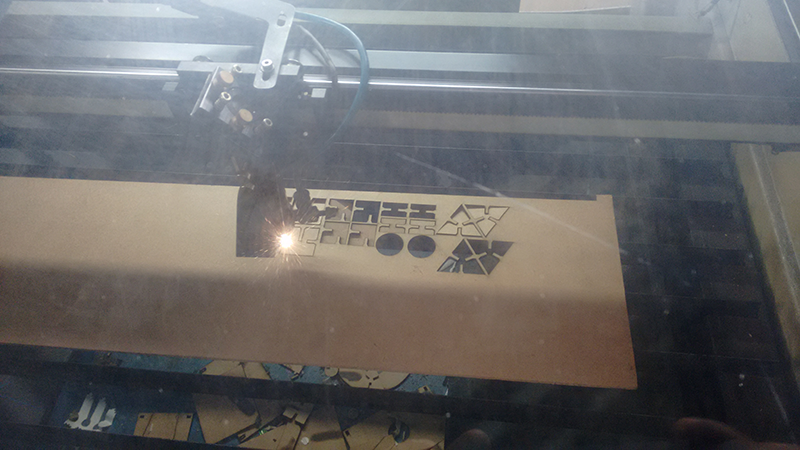
I am really happy with the results, the cut objects are perfectly cut with no black border on the edges, well a little bit of black dust is still there but that is not much of an issue.
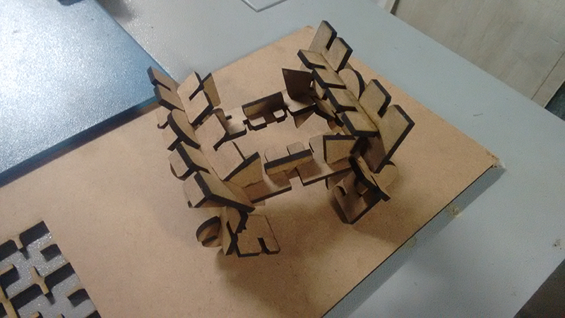
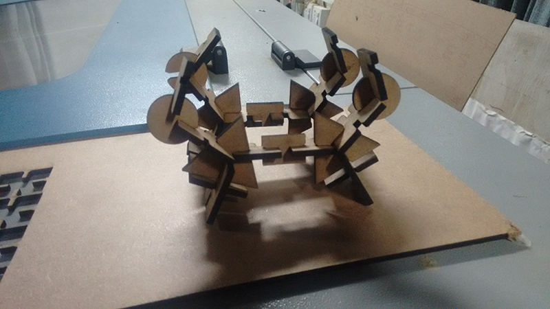
Now my pressfit kit is ready, this is like a lego bricks or a paper puzzle, we can make various objects with it, the joints are just perfect to hold on to each other
My experience using the machine
The machine is very precise untill and unless we take care of the bed level and we make provisions for kerb in our designs.
Neil had cautioned us not to open the safety door of the machine immediately after the cutting is done I did not pay much heed to it AND SO I SUFFERED. I was having a soar throat and dificulty in breathing for a day.
Lesson Learnt
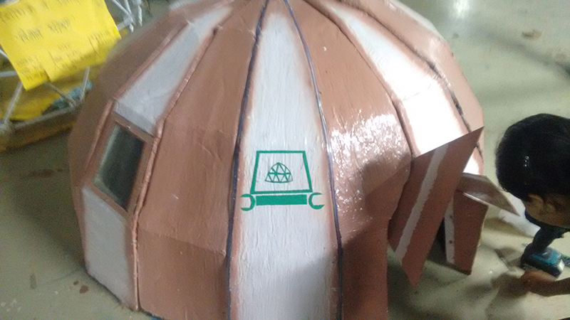
As far as my design is concerned the dome weighs around 750gram but it was able to sustain 17kg of weight
I am still not happy with the design, there was a lot of filling andgluing involved may be I should try something smaller in size before moving to such a large scale.
I will continue using this amazing machine for the coming weeks, THIS PAGE WILL BE UPDATED TILL THEN
Downloadable links
To download the original files click
this link
and
dxf file
Vinyl Cutting
For vinyl cutting assignment I made a sticker for my laptop.
Knowing the machine and materials
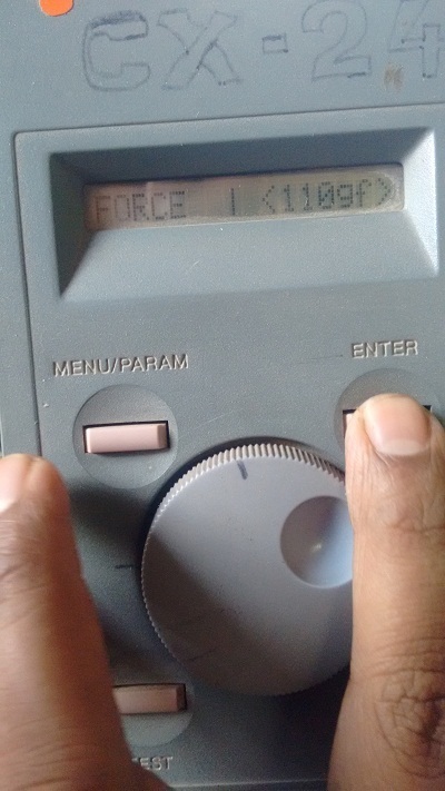
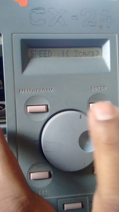
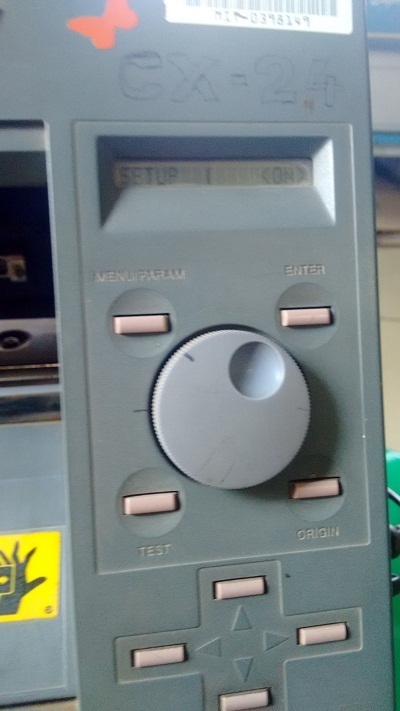
Our lab has a Roland vinyl cutting machine. The machine is operated through Fab Modules, other than this the machine itself has controls of its own such as speed of cutting, force, setting origin.
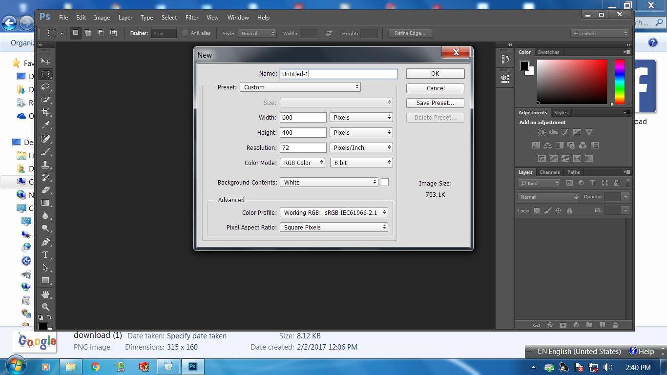
Photoshop and fab module
The FAB module accepts .svg or .png as an input for vinyl cutting machine.
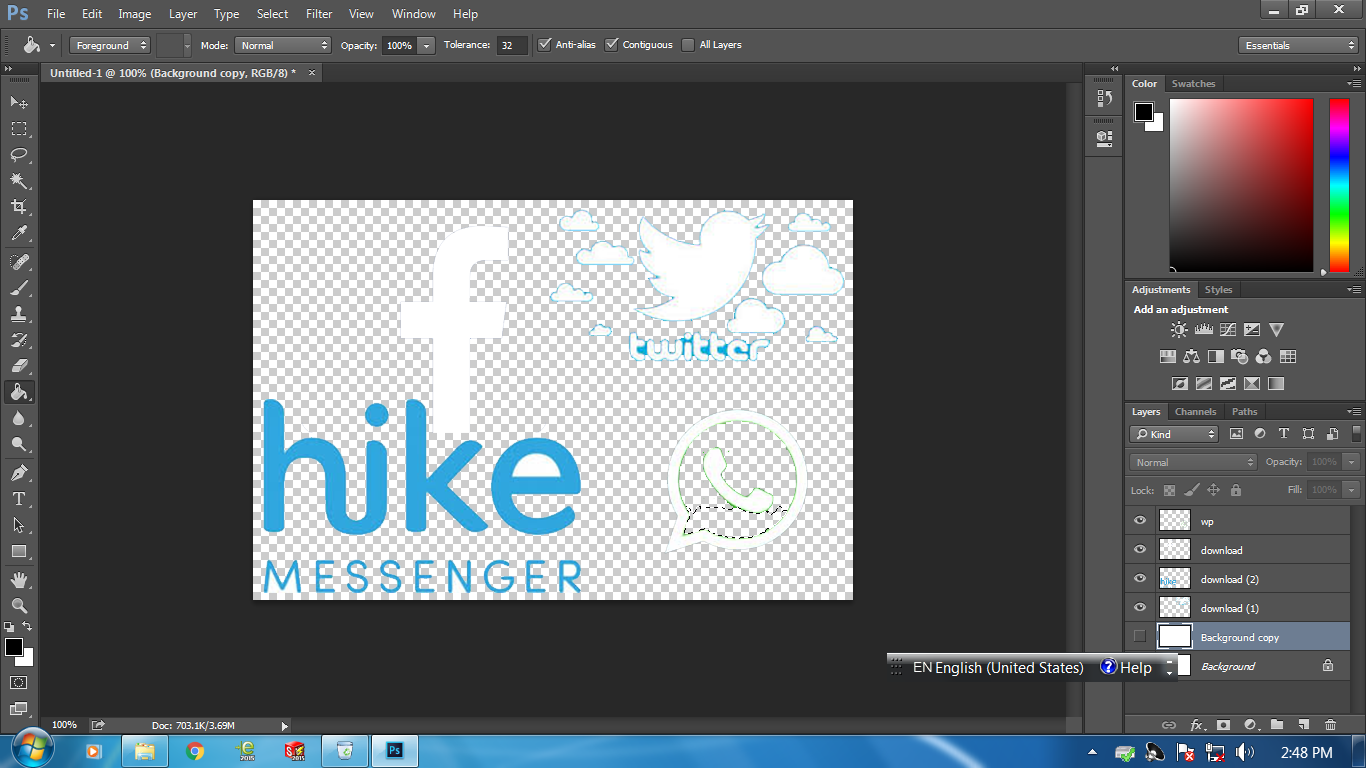
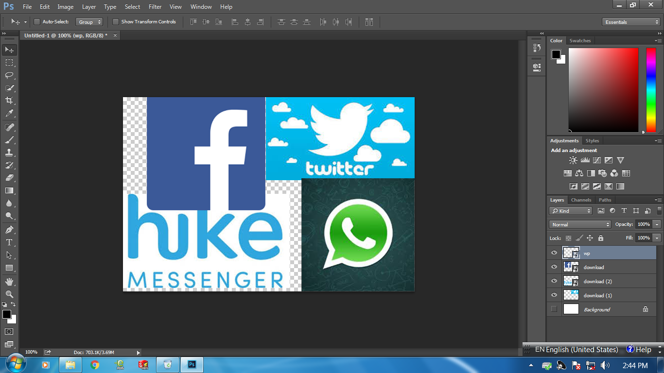
I used photoshop to creat the file. I arranged few social networking sites logo in the window and created a file.
Opened fab module on Ubuntu system and then selected the machine and material and loaded the file.
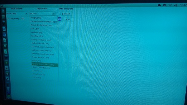 Getting the file ready and importing it in FAB module
The first design failed to cut, it was suppose to have a good resolution and continuous lines. The editing I did in Photoshop had broken few lines and resulted in blur images.
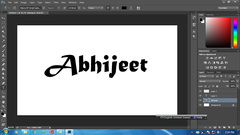
Thus I made another design, this time my name in a bigger font
I used the following setting
Speed-5cm/s, force-110gf, material-green vinyl
Prining and Peeling the stickers
Now comes the most tedious and skillful job, PEELING the sticker and pasting it on the laptop
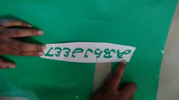
 The most skillful job
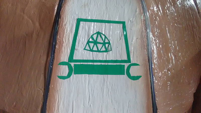
I also did my logo for the final project in this assignment, I made a logo which has a spanner and a dome enclosed in a trapezoid as my dome is a trapezoidal dome.
Download the file from here

My Experience with the tool
Vinyl cutter is a great tool to make stickers and copper circuits. A lot of intresting stuff can be done using this. Athough it is not as dangerous to use as a laser cutting machine precaution needs to be taken as it uses a sharp niddle to make the cuts.
This week we worked in a group for the first time. There are five students including me pursuing FabAcademy from Vigyan Ashram. Most of us are from a design background thus we enjoyed working on this assignment
Assignments brief
Neil had asked us to work in group and device different types of joints, he also stressed on using parametric design for the same.
Before this I was not aware of parametric designs, I searched for it on the internet followed some videos and started experimenting with it.
As a group assignment we decided to design and test one type of joint. I chose a Chamfer joint with varying angle and depth and tested each one of them for their fixity and strnght.
Learning Parametrics
I was awestruck by the kinds of possibilities Parametrics can have. Its time saving and lets us have a firm control on our designs. I felt that I had wasted so much time and energy repeating the same designs with minor changes.
I followed
this video
Using Paramterics and knowing how awesome it is
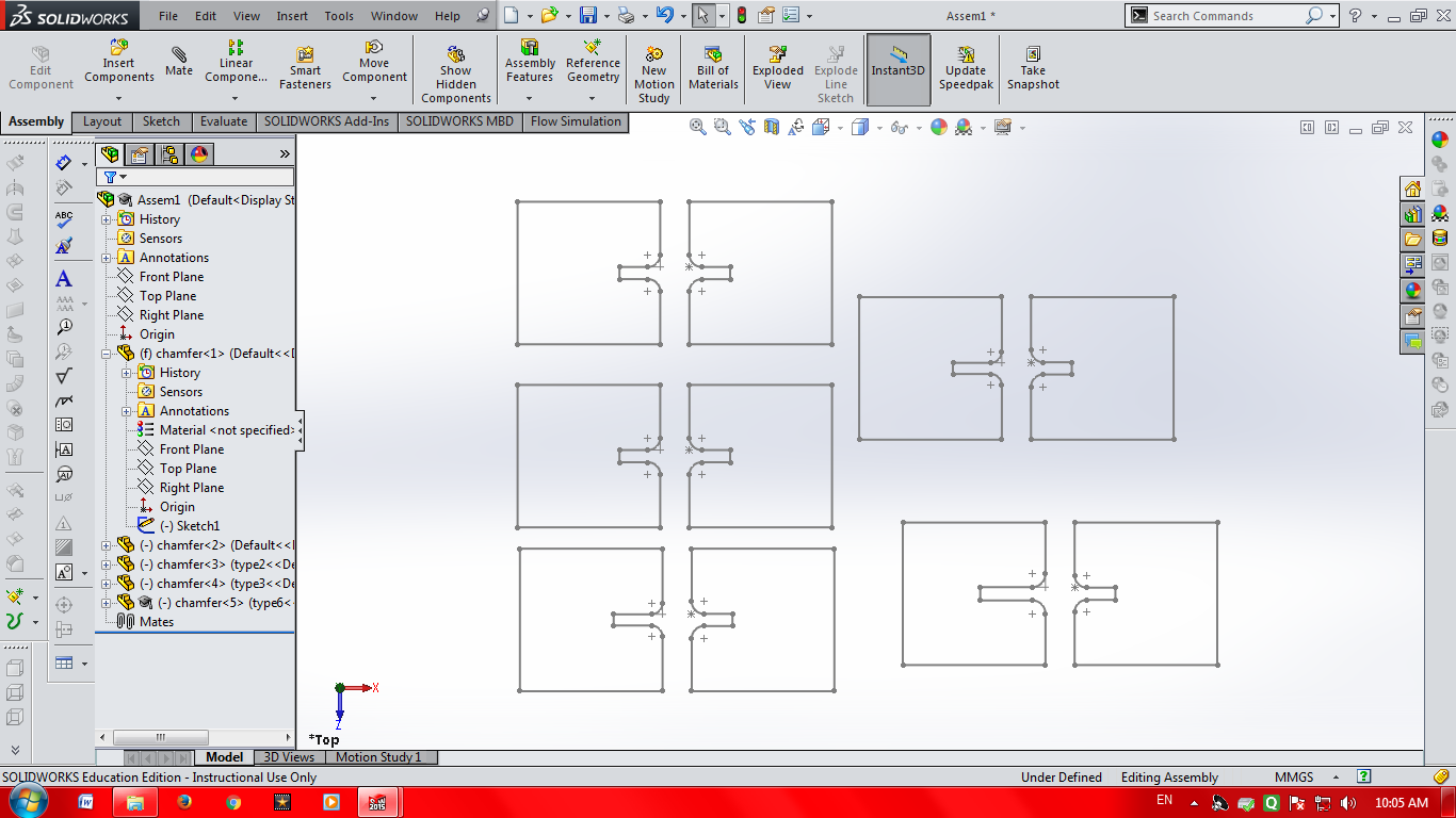
I choose chamfer joint for a specific resason. It is fairly easy joint and has two or three parameters to vary.
The best thing about parametrics in solidworks is that you can generate a lot of design by changing parameters.
I first generated a chamfer fit design in auto cad
Then I inserted an excel sheet INSERT-TABLE-DESIGN TABLE
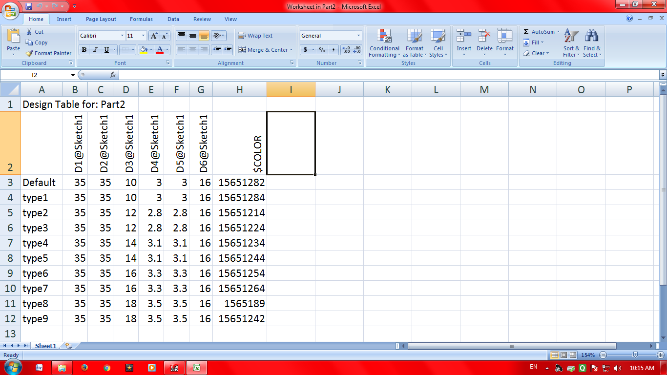
Thus by changing the dimensions in excel sheet I was able to generate multiple designs differring in their dimensions
Laser cutting and trying out the designs
I got the design printed and found out that the design with 2.75 to 2.95 mm slot is having the best fixity and strength.
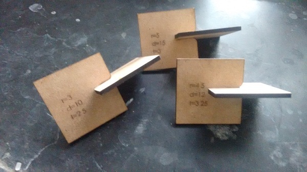
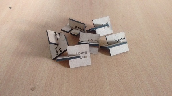
 Same joints with varying parameters
Working in a group has many advantages, I taught the other group members Parametrics and they taught me a lot of other types of joints. Flexible joints were amongst my favourite.
My Experience Using the tools
Parametrics is really an important tool in design especially when experimenting with same design with varying dimensions.
I found out that MDF does not compress to that extent, so we have to keep some tolerance for it. With living hinge the stiff MDF can be turned into wavy material.
I have not experimented with joints on acrylic or cardboard. I would be experimenting with the same in the coming weeks, thus this page will be updated
Downloadable File
To download the original file click this link