Final project
Project summarize
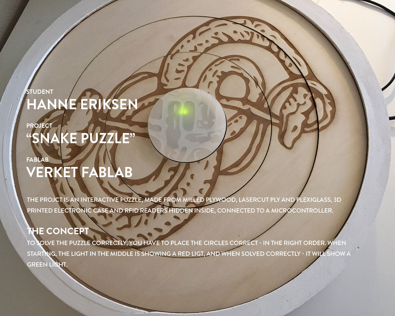
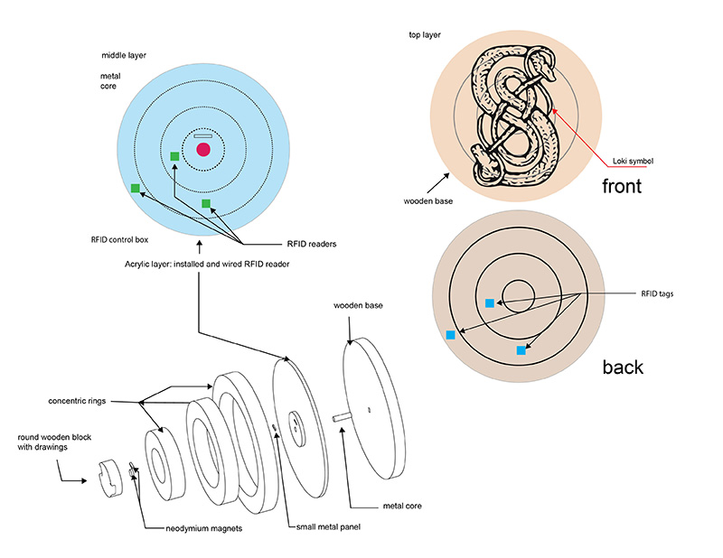
The project is a puzzle, containing 3 RFID readers and 3 RFID tags. All the tags are hidden inside the frame, and the puzzle gets unlocked when the image is showing correctly and the direction of the image is places correctly over the RFID readers.
When the puzzle is solved, the reader will activate the output device, where a LED will blink faster for each piece in place.
Design concept
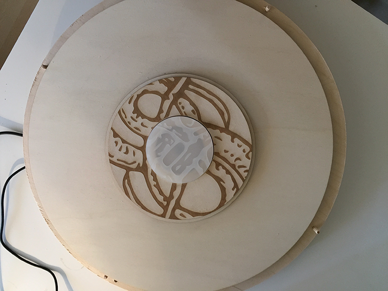
The is actually a part of an Escape Hunt game, where to teams are competing to pass through a labyrint of different rooms and tasks - where this game is a part of it. The puzzle is constructed with a back case,which is hollow and contain all the electronics. The front excist of 4 circles, where the middle circle is fixed in the middle. The other circles rotate, and has an image engraved onto it. The cirles also has RFID tags placed on the backside. The challenge is therefor to place the rings correctly, in the right order - for the puzzle to be solved. The RFID readers in the case, register what order the tags are activated, and activates an LED that blinks faster and faster for each ring correctly placed.
3D modelling
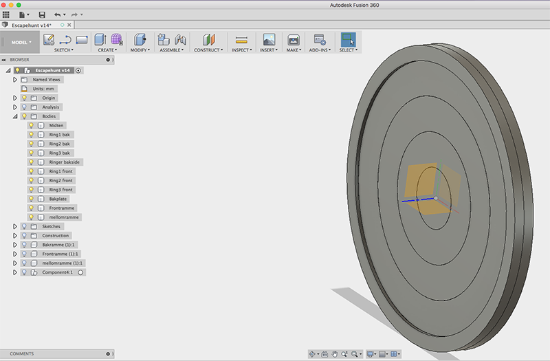
The 3D modell was designed in Fusion, on the basis of the design concept. The case was initially designed with 2 x18mm ply - but ended up adding 1x9mm ply in the middle, to make the case deeper.
Making the prototype
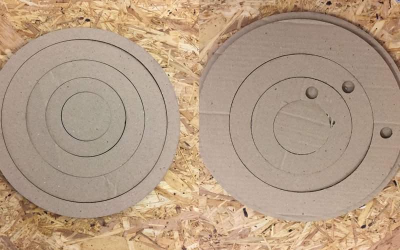
The design challenge was really how to construct the front, making the rings stay in place and not fall out, at the same time as they had to be able to rotate. The first prototype was cut on the lasercutter in cardboard, just to land how the functionality would be.
Prototype in ply
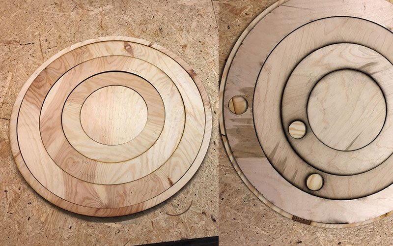
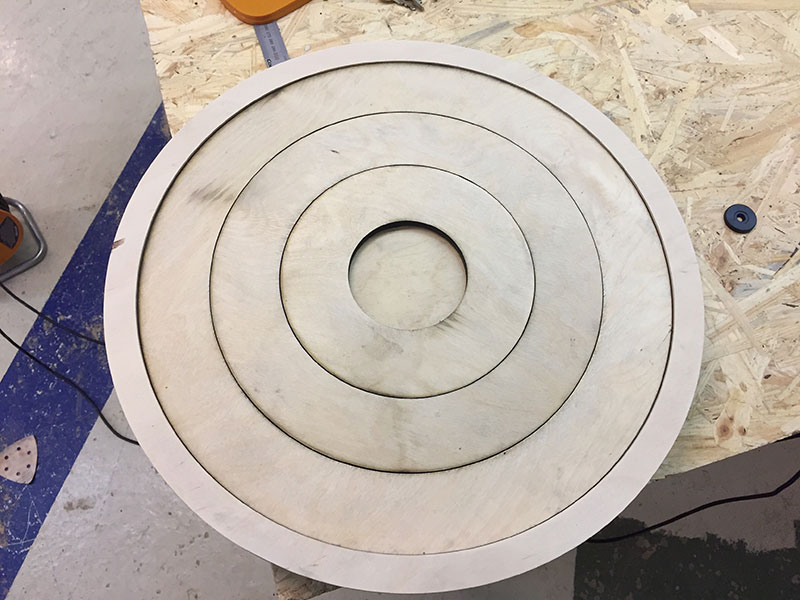
I then moved on to a protoype in 4mm plywood. This was also cut on the lasercutter.This time I had to adjust the number of rings and change the sizes of the rings. This was needed to make sure the RFID readers would fit behind them, and the RFID tags would with in the hole on the backside. The rings was designed with "double layer", where the back layer was a little bit bigger than the front. By assembling the rings in the right order so each one hold the prior one in place, made it possible for the rings to stay in place in the case, and also be able to turn around.
Final prototype
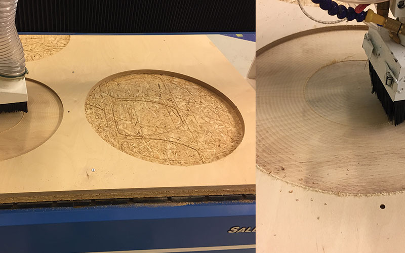
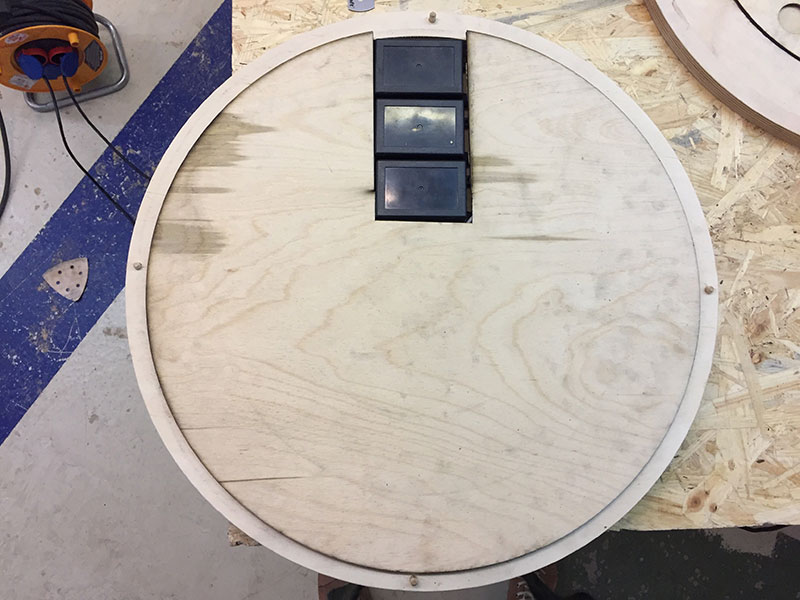
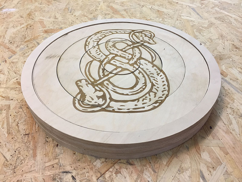
After landing the design of the rings, I then went on to mill the rest of the case. The case consist of 3 rings of plywood. 2x 18mm and 1x9mm. The rings are assemble by using wooden pegs that I milled 4 holes for.
The ring at the front has a small edge which holds the circles in place. The middle ring also has an edge, which works as a place holder for the 4mm plywood. This was needed so the cicles would not lay on top of the electronics.
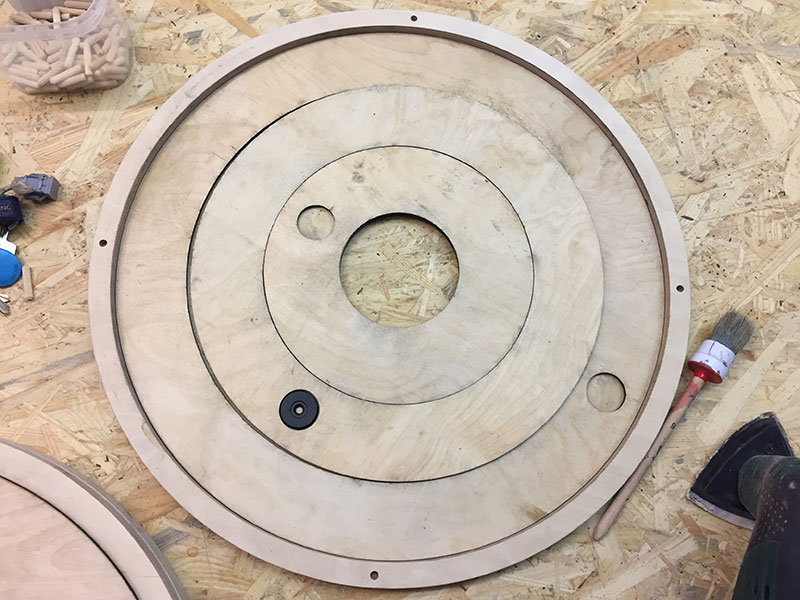
I also ended up adding an additional layer of 4 mm ply, that I call a "backplate". For the only reason to separate the rotating circles from the electronics.
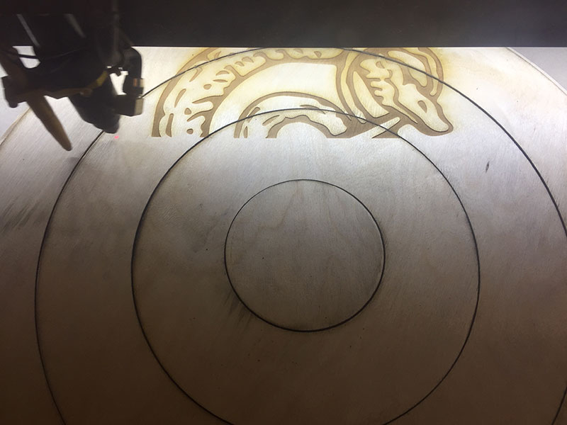
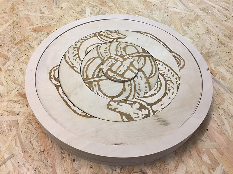
After finishing all the cutting and milling of the different pieces, I then engraved the image onto the rotating circles. The image was vectorised in Illustrator and exported as an Ai. file to the lasercutter.
The electronics
My biggest challenge by far is electronic design and production. Having needed to down priorites FabAcademy for other project deliverys made it an even bigger challenge the last two weeks.
I thought I was choosing a "electronic friendly" project, but that was untill it was time to connect everything together.
I started off with making my own Arduino board, where the idea was to design my own shield, where I would be able to "one click" assemble the RFID readers and not needing any/many cables.
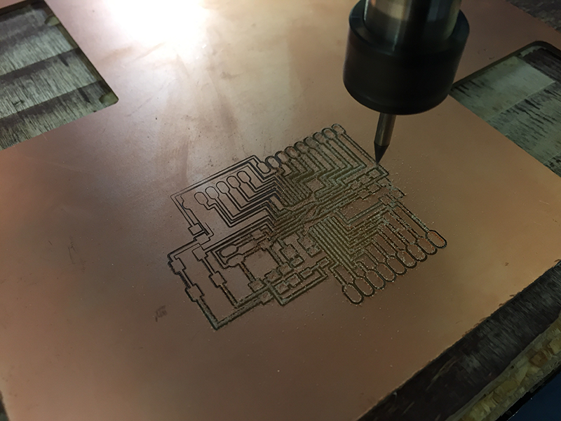
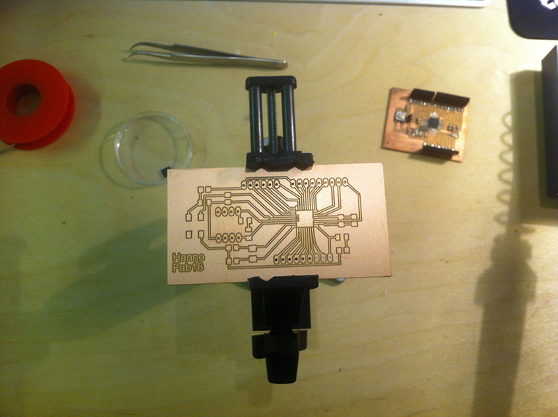
The board I started with is SatschaKit.
This board seemed suited for the project and together with the shield I was planning. The board was milled on a CNC with a 0.4mm mill. And I used a 1mm endmill for the cutout.
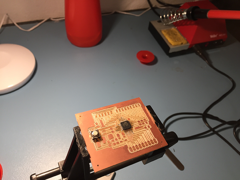
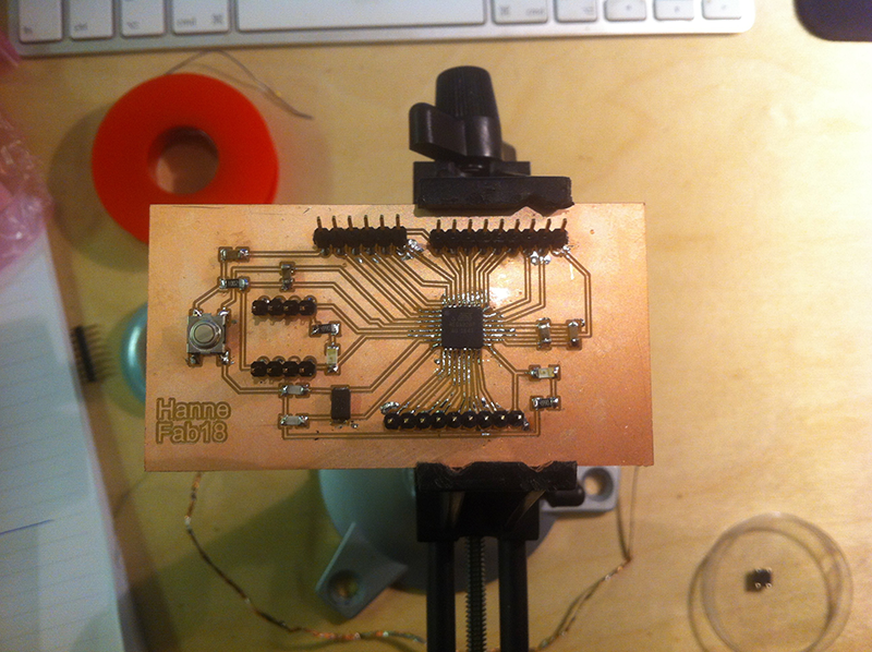
I then continued with the soldering of the board. I turned out to be lacking a few components, that I needed to make the board work correctly. I luckily managed to get that from my co-student Jakob. The components were one 16 MHz crystal and two 27 pF capacitors.
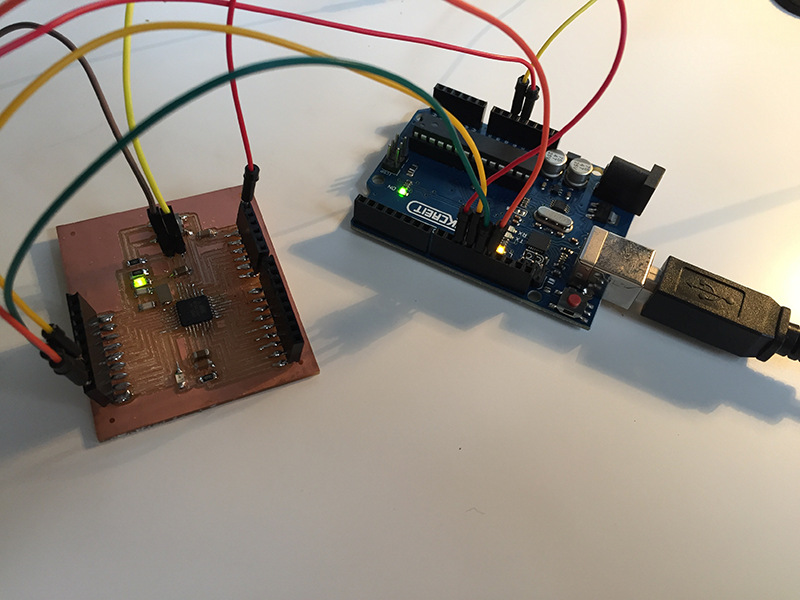
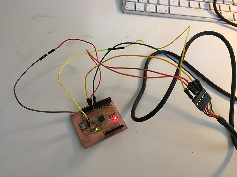
After soldering the board, I went on checking if the board worked correctly, and to program it - using an Arduino board.
To program the board as a separat Arduino, you need to:
• Open Arduino IDE
• Select proper programmer (for example Arduino as ISP or USBtinyISP)
• Select Arduino UNO as board
• Click on tools->Burn Bootloader
(You can find more details here)
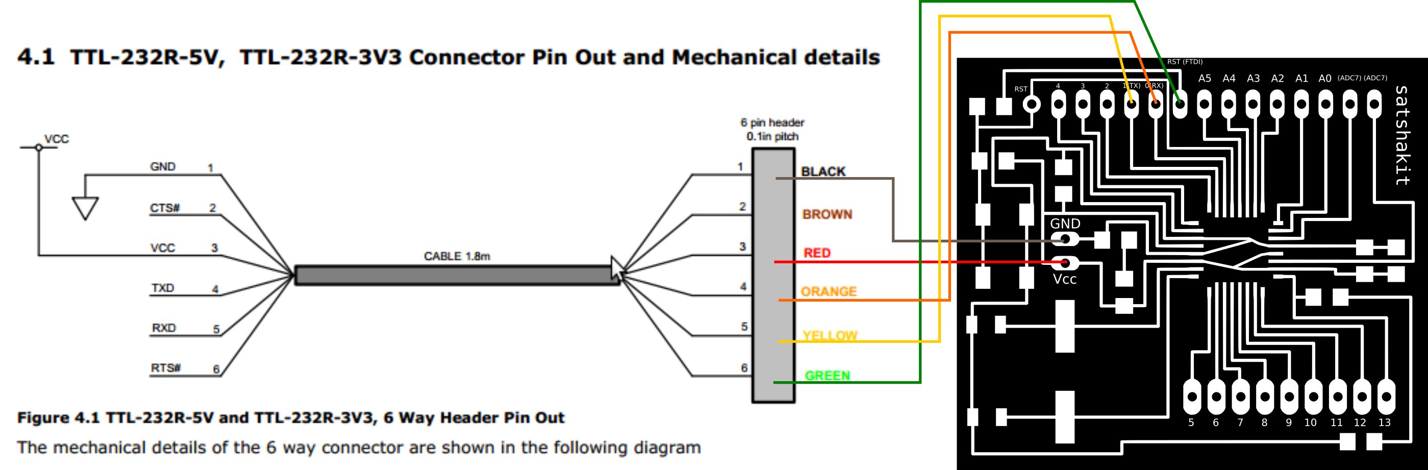
After programming the card, I then switched over to an FTDI cable and uploaded the "Blink" example, to test that everything was working. Which it was.
See the schematics below for how to hook up with the FTDI cable.
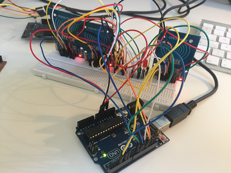
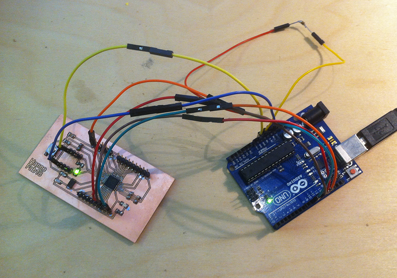
Making sure the card was working, I then went back to the original Arduino and connected all the RFID's by using a breadboard. I wanted to make the electronics and work out the code before I started to assemble final prototype.
Programming the game
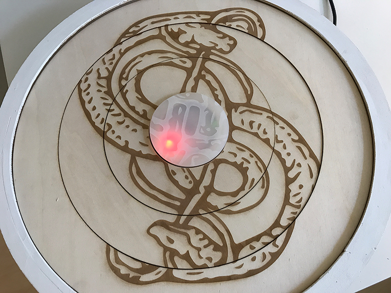
The game consist of the microcontroller, 3 RFID readers and 2 LEDs. Each of the RFID tokens are placed in specific spots at the back of the circles. When the readers are reading the tokens in a specific order, the red LED will start blinking, and for each circle being read in the right order it will start blinking faster. When the player in the end has the final puzzle, it will blink fast with both of the LEDs.
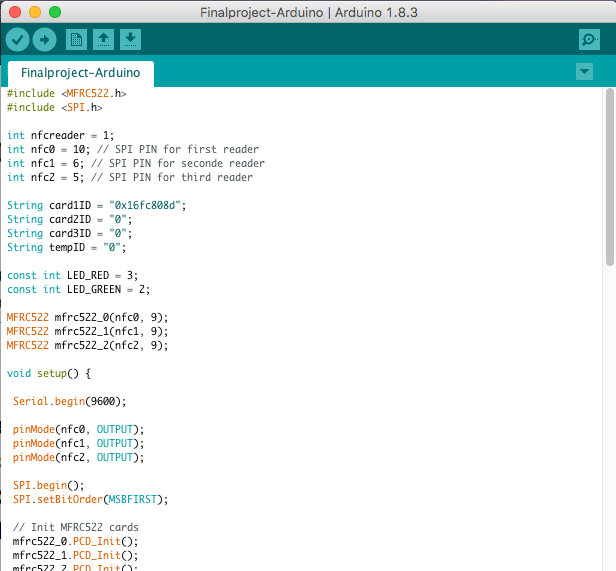
Since the microcontroller is an "Arduino" - I used the Arduino IO to programme the game. To be able to programme the RFID, you need to include the libraries:
MFRC522.h
SPI.h
I decleared the LEDs to the pins 3 and 2, and the RFID readers was decleared to pin 10, 6 and 5.
Initially, the plan was to just the let RFID readers give feedback when all three was read, but it suddenly got a lot more complicated when I realized that they had to be in a certain order, otherwise it would just be confusing. Therefore, the red LED was defined as "ON" when starting, giving the player a feedback that the game was active. The RFID readers was then programmed to start searching for the tokens. The inner token had to be found first, the next circle second and so on.
You can download the codefile here or from the "Files" page.
Designing my own "Satscha Kit" board
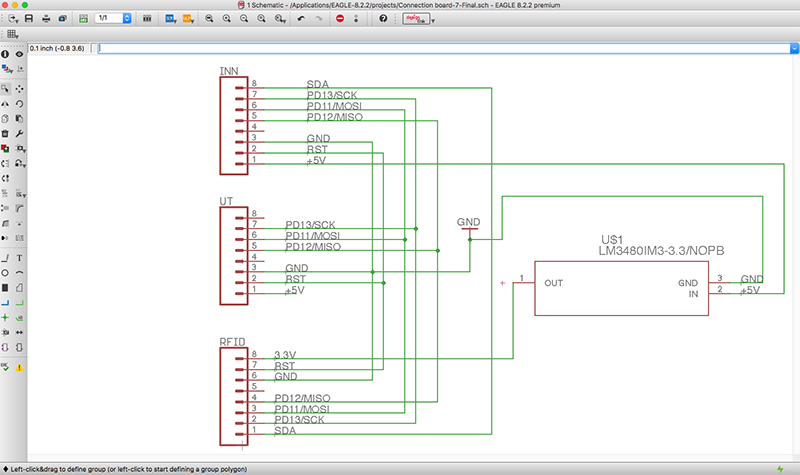
After getting the electronics working, I found out that I could not use the Satscha Kit for my final project - since this was not my own design. I therefor started all over again, desiging my own board in Eagle, with the same component and functionality - but I also added some more ground and 5v pins, since I did not want having to use a breadboard for my final project.
I used Eagle for my circuitboard design, where I had to import the footprints from the dealer I ordered the crystal from (DigiKey), since this was not in the original library.
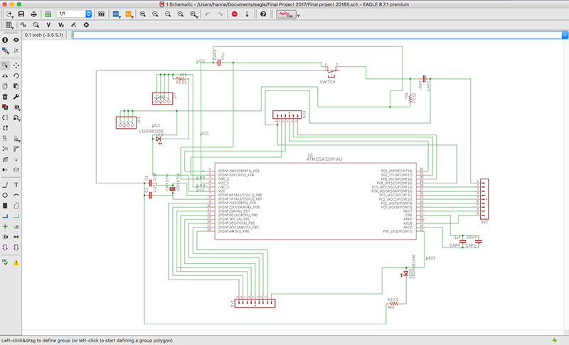
After adding all the components and connecting them in the right order, I then went over to the board view - and started moving around the compontent to find the best possible routing of the circuit.
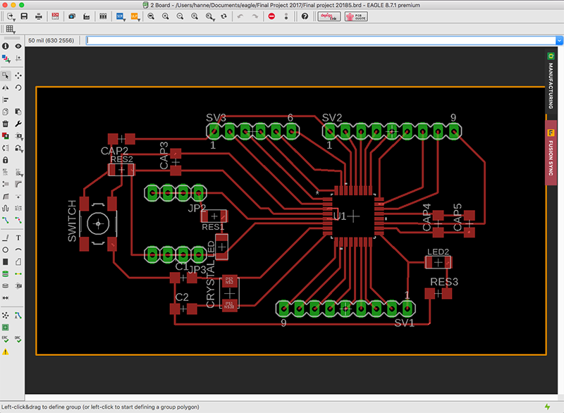
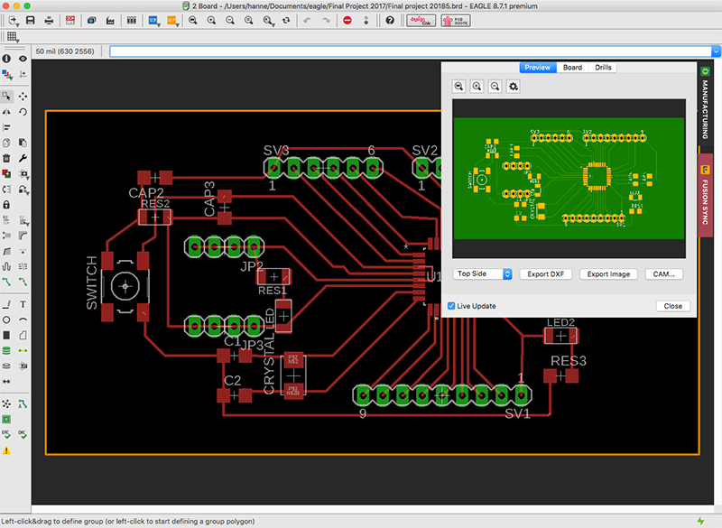
After the design process was finished, I exported the DXF file from Eagle, and imported it into Fusion360 for the milling.
I tried to work out the new function in Eagle, where you can sync files between Eagle and Fusion, but I got stuck on adding milling paths on the model - so I imported the DXF and created the board that way.
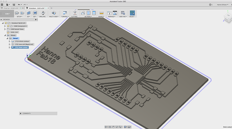
I used the CAM module in Fusion to set up all the milling paths.
The milling was done with a 0.4mm endmill for the paths,the drilling holes was made with a 1mm endmill, and the cut out was milled with a 3mm endmill.
Unfourtunatly, my phone was stolen after this point - and the images fromt the milling process was lost.
After I was done milling, I started soldering the components.
I then followed the same process as with the Satscha Kit, when it was time to program the board. You can find the details at higher up on this page.
I also used the same process when it was time to program the board. I used an Arduino as an ISP - and wired it up the same as with the Satscha Kit.
Connection Board
When I was working with the code, I started notice that the reading was very un-even. Moving the readers further a part solved it...but that meant that the shield would not work, since the readers also had to reache the furtherst and closes tags. And the PCB I got in hand, only about 15x15cm.
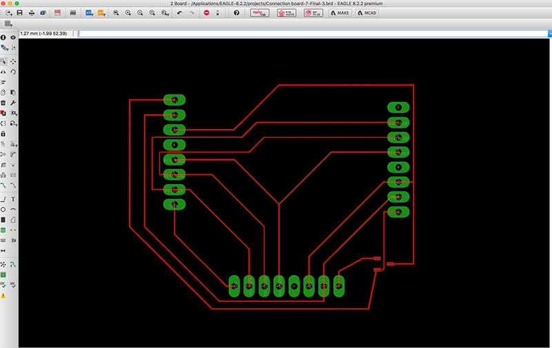
That meant that the connectionboard in EAGLE I had started to design, would stay an idea.
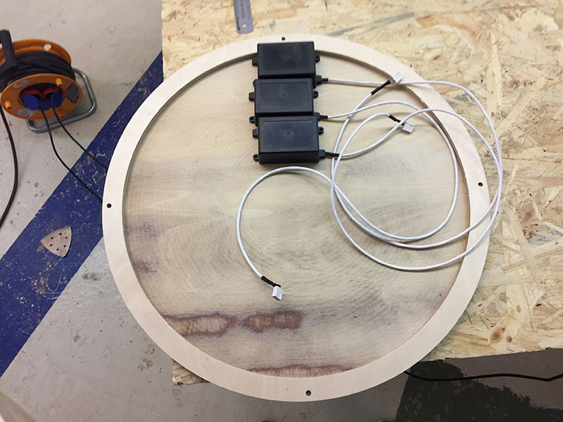
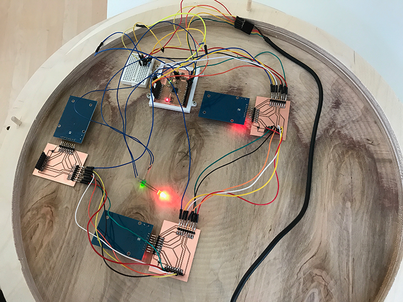
So the project plan then moved on to making 3 separate connection boards, for all 3 readers. The readers also needed an 3.3v regulator - so I added that onto it.
After finishing the design, the file was exported from EAGLE, by clicking the "MAKE" icon in the top menu, and creating an MCAD file that was directly sendt to Fusion360.
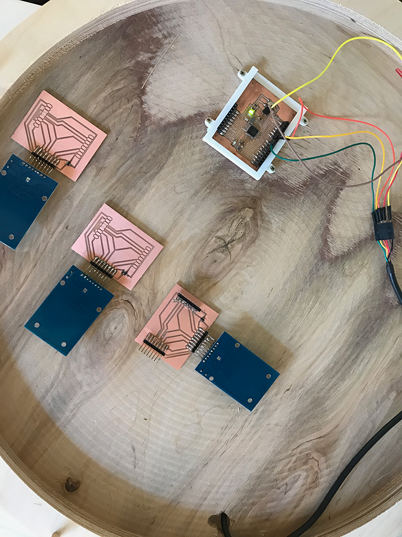
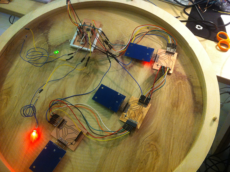
3 connection boards, soldered to the RFID readers and connected to the Stacha test board.
3D modelling & Printing
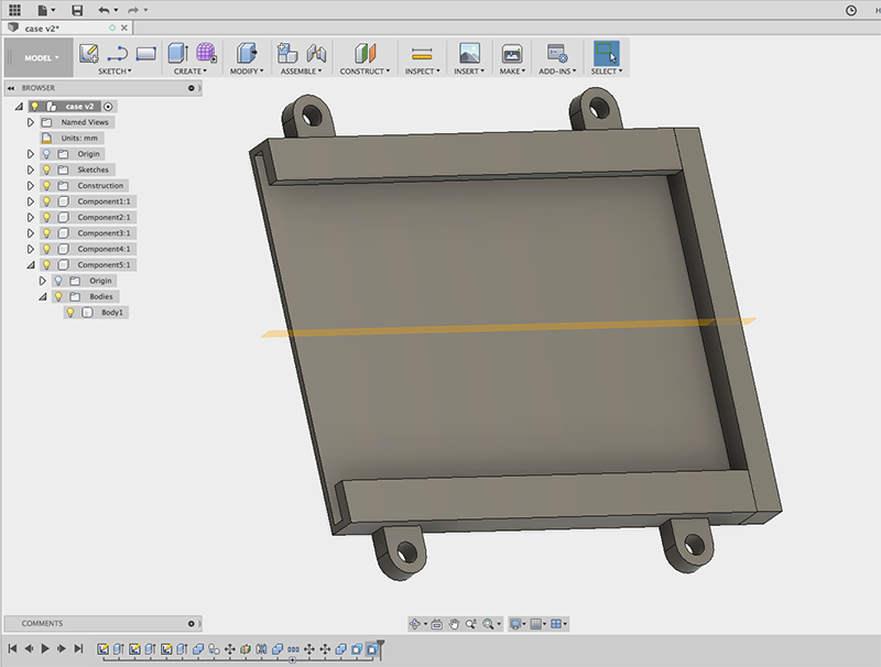
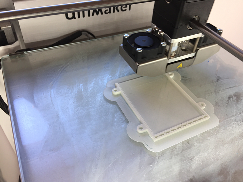
For 3D printing, I ended up modelling and printing a case for the Satscha board - so I would be able to take it in and out, but still stay in place. The model was made in Fusion360, and the model was printed on an Ultimaker 2+ with 0.1 high resolution print.
The assembly and adjustments
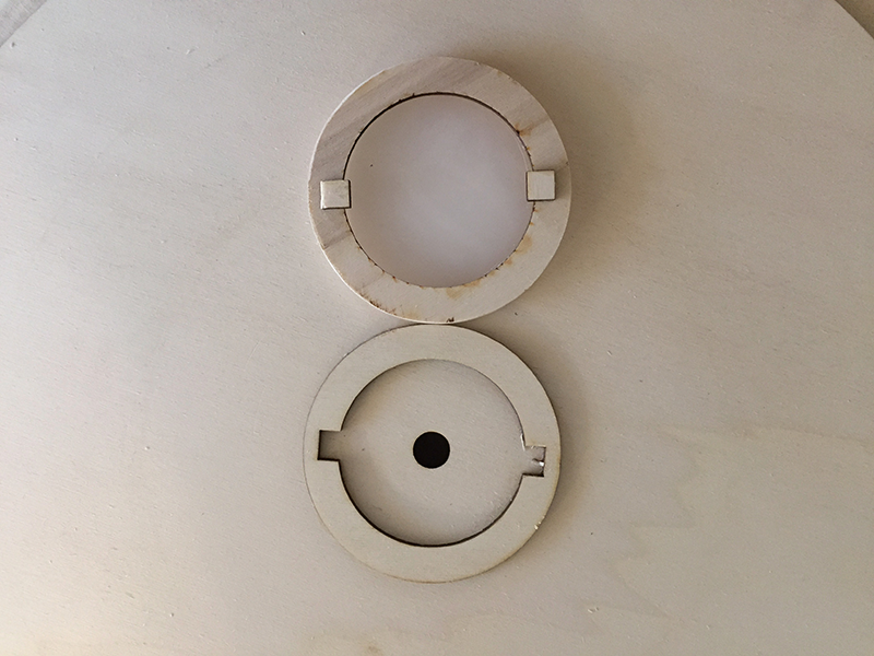
I put the case together, I decided to make a small adjustment to the front element. For the output of the game, I wanted the middle circle to be lighting up. So I re-made the inner circle - in 4mm frosted plexiglass. I also made some changes to the backside of the innercircle. I realised it would be a bit confusing "What side is up" when solving the puzzle, so I made a "lock" at the back, to keep the innercircle in place.
First board, with Satshca Kit circuitboard
Second board, with my own designed circuitboard
The final!
When soldering and hooking everything up, I made a few observations for changes I would have liked to make/add if I had the chance.
• I would have intergrated the LED's more, they were totally forgotten about and resulting the need for adding an extra breadboard.
• I Would have used other types of connection pins on the connection board. It would have been nicer to have used a FLAT cable and header pins, instead of having a spagetti'ish result.
But I have to say, after the limited time I had to work on the project, I am super happy with the result! And there was not any issues to connect all the end components together.
Update 2018
Since I was required to make a new microcontroller, I did manage to integrate the LED's on the new board. Unfortunately, when I was moving everything over to the new microcontroller, I managed to break it - when trying to remove the no longer needed breadboard.
What worked and what did not:
- I did not take into account the speed of the rotation of the circles. If the player moved it too fast, the readers would be too slow to read the tokens. Therefor, it would be easy to get confused about why the lights were blinking/not blinking.
- The middle circle would have to be fastened in a better way, so it does not fall off when rotating the other circles. But yet be easy to remove for setting a new game.
- I would have liked to add some sound as well, and not just the lights. Which would have emphasized the "points" the player get for placing each circle correct.
- The circles makes a lot of friction, which is a challenge for rotating them while hanging upwards. But if they were too loose, they would "hang" on the middle piece, and fall out of their track. When lying down, the friction was not a problem.
Bill of materials
18mm plywood
4mm plywood
6mm pleksiglass
3 RFID readers
3RFID tags
1 3.3v reglator
Cables
ATMEGA328P 32 microcontroller
16Mhz/18pF crystalgreen
Green led
Yellow led
6 x 6 x 3.1 mm switch
10K resistor
499 resistor
10uF 1206 capacitor
1uF 1206 capacitor
27 pF capacitors
100nF 1206 capacitor
2.54 mm pin header
2.54 mm pin header
FTDI cable
Licence
Copyright (c) 2017 Hanne Eriksen
Permission is hereby granted, free of charge, to any person obtaining a copy of this software and associated documentation files (the "Software"), to deal in the Software without restriction, including without limitation the rights to use, copy, modify, merge, publish, distribute, sublicense, and/or sell copies of the Software, and to permit persons to whom the Software is furnished to do so, subject to the following conditions: The above copyright notice and this permission notice shall be included in all copies or substantial portions of the Software.
THE SOFTWARE IS PROVIDED "AS IS", WITHOUT WARRANTY OF ANY KIND, EXPRESS OR IMPLIED, INCLUDING BUT NOT LIMITED TO THE WARRANTIES OF MERCHANTABILITY, FITNESS FOR A PARTICULAR PURPOSE AND NONINFRINGEMENT. IN NO EVENT SHALL THE AUTHORS OR COPYRIGHT HOLDERS BE LIABLE FOR ANY CLAIM, DAMAGES OR OTHER LIABILITY, WHETHER IN AN ACTION OF CONTRACT, TORT OR OTHERWISE, ARISING FROM, OUT OF OR IN CONNECTION WITH THE SOFTWARE OR THE USE OR OTHER DEALINGS IN THE SOFTWARE.