#week4
Electronics Production
This weeks assignment
Make an in-circuit programmer by milling the PCB and optionally, trying other processes.
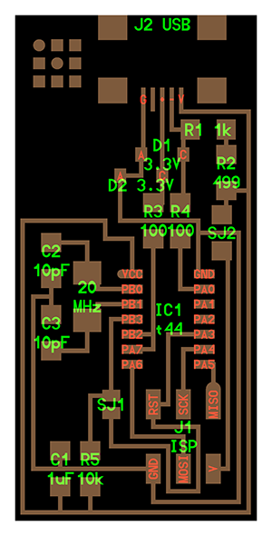
hello.ISP.44
hello.ISP.44 Traces (file not for milling)

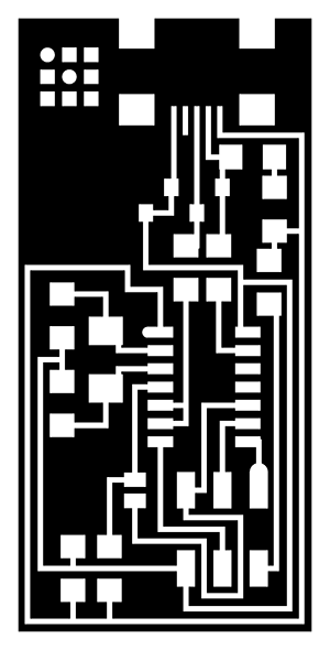
hello.ISP.44 Interior (file not for milling)
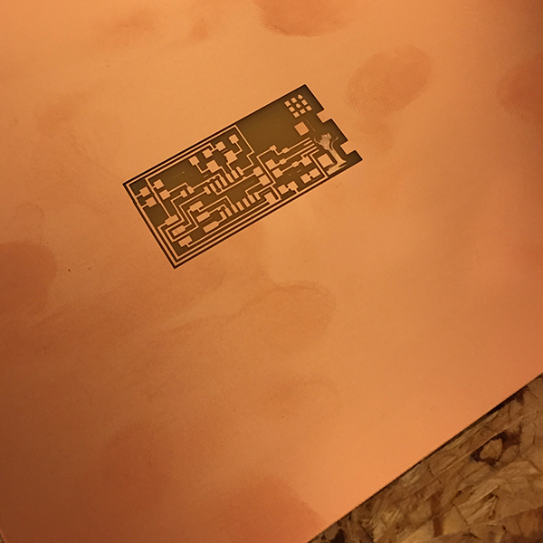
creating the toolpath for the PCB
To create the toolpath I first imported the hello.isp.44.traces.png into Inscape and used the trace bitmap command to generate a vector image which I exported as hello.isp.44.traces.pdf for import into RhinoCam. I first created one path for the pocketing and the second path for the cutout, before I then exported the paths to gcode and uploaded it to the CNC software MACH3.
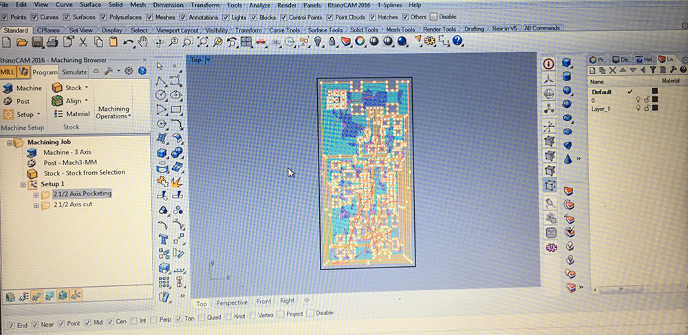
The CAM setting for the toolpaths are:
2 1/2 axis pocket - PCB path milling
Endmill Ø0,4 mm
Feed 300mm/ per minute
Spindle 20 000 rpm
50% Feed when plunging, approaching and engaging
100% Feed when cutting, retracting and departing
80% stepover between paths
Tolerance 0,01 mm
Stock to leave 0 mm
Total cut depth 0,1 mm
Pass depth 0,1 mm
Climb direction
10 degrees entry ramp to begin cutting
Clearance plane from stock max +6 mm
2 1/2 axis cut - To cut the card out of the stock
Endmill Ø3 mm
Feed 1200mm/per minute
Spindle 20 000 rpm
50% Feed when plunging, approaching and engaging
100% Feed when cutting, retracting and departing
No stepover, only one profile path.
Tolerance 0,1 mm
Stock to leave 0 mm
Total cut depth 1,8 mm
pass depth 0,6 mm
Climb direction
10 degrees entry ramp to begin cutting
Clearance plane from stock max +6 mm
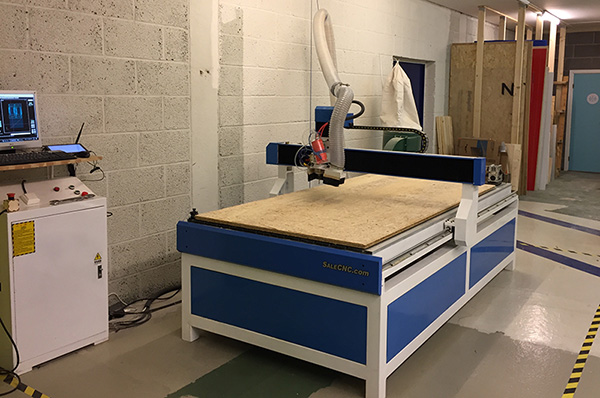
Milling the PCB
The machine used for milling the PCB is SalesCNC with the spesifications:
CNC Router Milling XJ1224 machine.
X1200mm Y2400mm Z200mm
2,2kw Spindle
ER20-Collet
Rotary A-akse Ø150mm
RapidMove 4000mm/min
Rotary lengde ca1200mm
Spindle watercooled
Ballscrew's
spindle speed - 24000RPM
Precision resisjon 0.01mm
Spindle - inverter
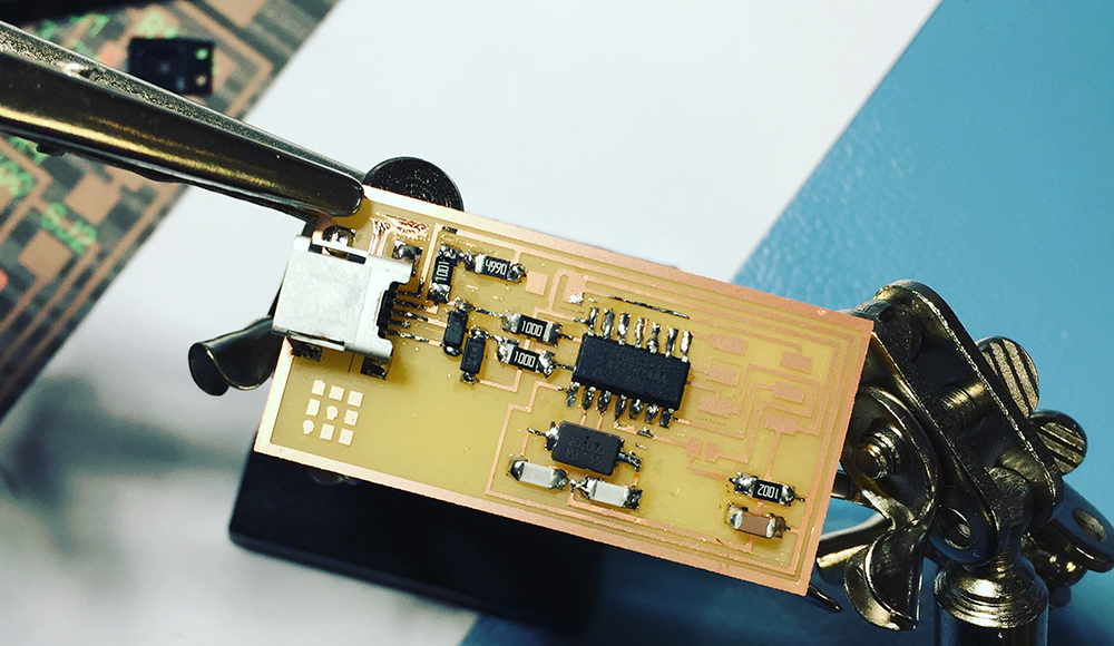
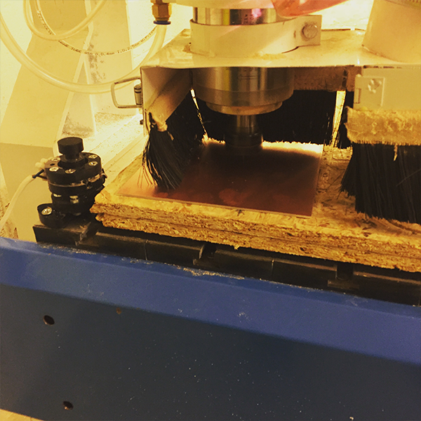
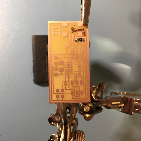
When milling the PCB FR1 I used double sided tape to stick it onto the CNC. After milling it I kind of realised that I could have exploited the PCB sheet a bit better and not milling the board in the middle of it. I place this on the Rooky account and playing it safe! There were some small areas left that was not completly milled, without having any effect on the functionality of the board. Checking with the file in Eagle, there was not any errors - and the problem was solved in later circuit milling by lowering the z value to 0.3.
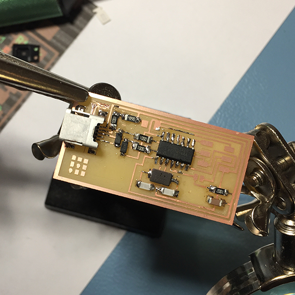
Soldering the components
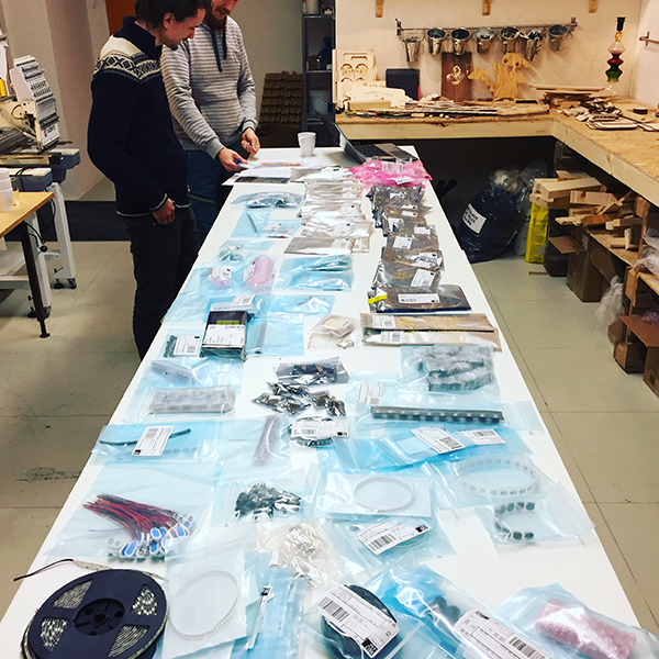
Components list is as following:
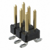
6 pin Header
609-3487-1-ND BERGSTIK HDR 6POS .100" DR SMT
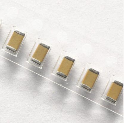
10pf capacitor
AP CER 10PF 50V NPO 1206
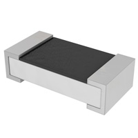
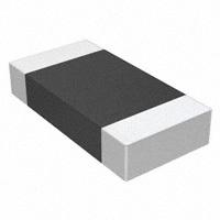
1K Resistor
RES SMD 1K OHM 1% 1/4W 1206
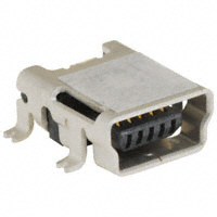
USB - mini
UX60A-MB-5ST

2 100K Resistors
RES SMD 100 OHM 1% 1/4W 1206
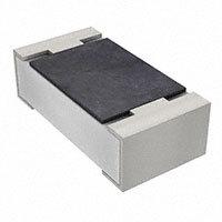
10K Resistor
RES SMD 10K OHM 1% 1/10W 0603
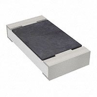
0 OHM Resistor
RC1206JR-070RL
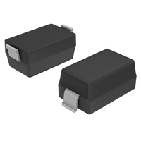
2 DIODE ZENER 3.3V
BZT52C3V3-7-F
499 Resistor
RES SMD 499 OHM 1% 1/4W 1206
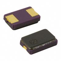
Crystal 20mhz
CRYSTAL 20.0000MHZ 8PF SMD
Capacitors 10pf
CAP CER 10PF 50V C0G/NPO 1206
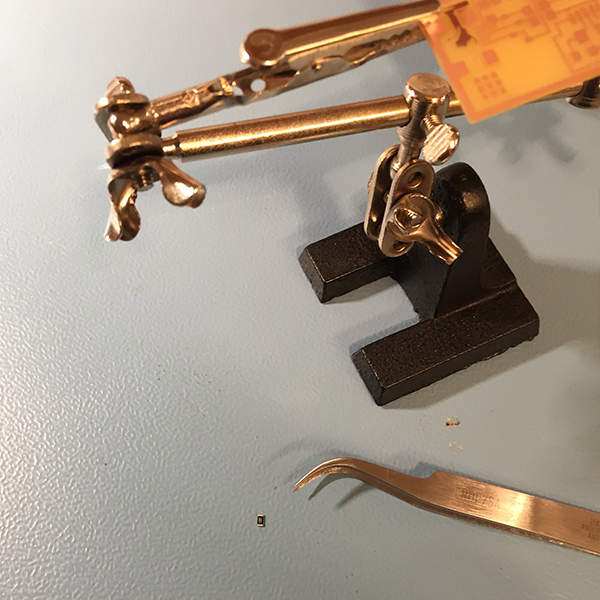
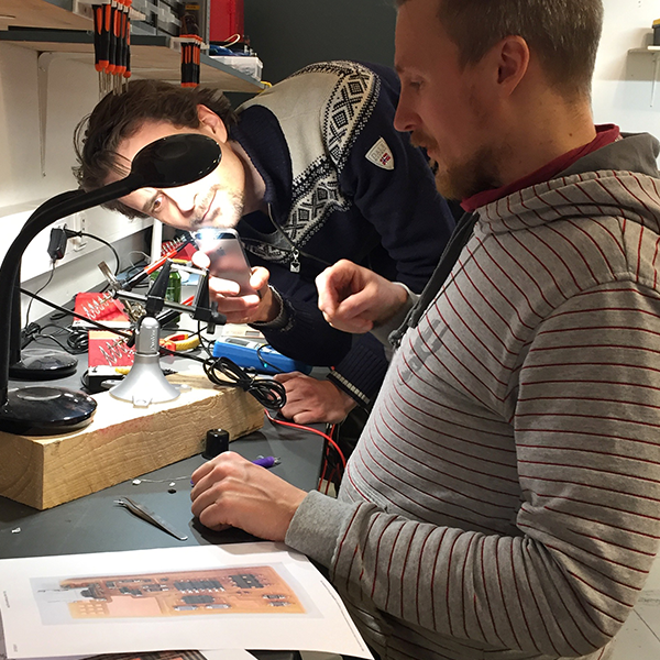
When we had organized and allocated all the components (turned out we were missing the 6 pin header that had not yet arrived) - it was time to start soldering the components onto the board. I started off with the smalles components first - working my way up to the USB. The most difficult one to solder was definately the USB. The description for the placing of the components and which to use was not exactly easy to figure out, since there was several examples with different images and their components. After some research we found out that one of the components are supposed to be removed after the FabISP had been programmed. During soldering we also discovered that the milling process had skipped one part on the board - creating a short circuit. This was easily fixed by using a knife to break the circuit.
Being totally new to electronics (at this level) and having to do this project by myself, would definately have been a real challenge placing the components correctly (what directions and what to watch out for). But, since we did this as a group activity together with our instructor, it ended up being a fun project that made it a manageable task. Since I am already familiar with soldering, the biggest lessons I learned this week was how to read the drawings for the circuit and (to an extent) what the different components do and how to fabricate a circuitboard.
Golden lessons:
R means resistor
C means capacitor, Mhz indicates an occilator and diodes have a direction.
(Positive Anode Negative Cathode = the PANC rule.
The arrow points from + to -, which means from A to C - which means the tiny line on the diode shall be towards the Cathode.)
Programming the board
For programming the board, I followed the steps in the FabAcademy tutorials - Programming FabISP using Mac by Anna Kaziunas France,
see her tutorial below:
***********************************************************************
Download the FabISP Firmware
https://github.com/Academany/FabAcademany-Resources/blob/master/files/firmware_44.zip
Open terminal and navigate to the desktop
cd ~/Desktop/
Move into the newly created firmware directory on your desktop
cd ~/Desktop/firmware
---------------------
Connect the board to the AVR
Make sure that the mini USB connector for the FabISP you are trying to program is plugged into your computer.
AND that a separate pogramer is plugged in to the 6-pin programming header. (this could be another working FabISP or the ATAVRISP2, a USBtiny, an AVR Dragon, etc.)
Helpful ATAVRISP2 Programmer Light Indicator Messages:
If you connect the programmer to the 6-pin programming header on your FabISP board and you get:
Green Light: means that the header is soldered correctly, the board is getting power.
Yellow Light: means that the board is getting power, but most likely the 6-pin programming header is not soldered correctly
Red Light: means that the board is not getting power - check for shorts.
---------------------
Program the FabISP
- Navigate to the directory where you saved the FabISP firmware. If you followed the instructions above, this will be the desktop.
- Open your terminal / command line interface and move to the firmware directory.
- For Mac users who downloaded the modified firmware:
cd Desktop/fabISP_mac.0.8.2_firmware
---------------------
Next you need to compile the firmware:
Type:
make clean
If you are successful - you will see this response from the system:
akaziuna@Titan:~/Desktop/firmware$ make clean
rm -f main.hex main.lst main.obj main.cof main.list main.map main.eep.hex
main.elf *.o usbdrv/*.o main.s usbdrv/oddebug.s usbdrv/usbdrv.s
Type:
make hex
If you are successful - you will see this response from the system:
akaziuna@Titan:~/Desktop/firmware$ make hex
avr-gcc -Wall -Os -DF_CPU=20000000 -Iusbdrv -I. -DDEBUG_LEVEL=0
-mmcu=attiny44 -c usbdrv/usbdrv.c -o usbdrv/usbdrv.o
avr-gcc -Wall -Os -DF_CPU=20000000 -Iusbdrv -I. -DDEBUG_LEVEL=0
-mmcu=attiny44 -x assembler-with-cpp -c usbdrv/usbdrvasm.S -o usbdrv/usbdrvasm.o
avr-gcc -Wall -Os -DF_CPU=20000000 -Iusbdrv -I. -DDEBUG_LEVEL=0
-mmcu=attiny44 -c usbdrv/oddebug.c -o usbdrv/oddebug.o
avr-gcc -Wall -Os -DF_CPU=20000000 -Iusbdrv -I. -DDEBUG_LEVEL=0
-mmcu=attiny44 -c main.c -o main.o
avr-gcc -Wall -Os -DF_CPU=20000000 -Iusbdrv -I. -DDEBUG_LEVEL=0
-mmcu=attiny44 -o main.elf usbdrv/usbdrv.o usbdrv/usbdrvasm.o usbdrv/oddebug.o
main.o
rm -f main.hex main.eep.hex
avr-objcopy -j .text -j .data -O ihex main.elf main.hex
avr-size main.hex
text data bss dec hex filename
0 2020 0 2020 7e4 main.hex
----------------------
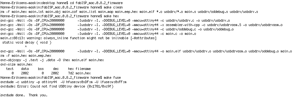
Next, you need to set the fuses so your board will use the external clock (crystal)
Type:
make fuse
If you are successful - you will see the following response from the system:
akaziuna@Titan:~/Desktop/firmware$ sudo make fuse
avrdude -c usbtiny -p attiny44 -U hfuse:w:0xDF:m -U lfuse:w:0xFF:m
avrdude: AVR device initialized and ready to accept instructions
Reading | ################################################## | 100% 0.01s
avrdude: Device signature = 0x1e9207
avrdude: reading input file "0xDF"
avrdude: writing hfuse (1 bytes):
Writing | ################################################## | 100% 0.00s
avrdude: 1 bytes of hfuse written
avrdude: verifying hfuse memory against 0xDF:
avrdude: load data hfuse data from input file 0xDF:
avrdude: input file 0xDF contains 1 bytes
avrdude: reading on-chip hfuse data:
Reading | ################################################## | 100% 0.00s
avrdude: verifying ...
avrdude: 1 bytes of hfuse verified
avrdude: reading input file "0xFF"
avrdude: writing lfuse (1 bytes):
Writing | ################################################## | 100% 0.01s
avrdude: 1 bytes of lfuse written
avrdude: verifying lfuse memory against 0xFF:
avrdude: load data lfuse data from input file 0xFF:
avrdude: input file 0xFF contains 1 bytes
avrdude: reading on-chip lfuse data:
Reading | ################################################## | 100% 0.00s
avrdude: verifying ...
avrdude: 1 bytes of lfuse verified
avrdude: safemode: Fuses OK
avrdude done. Thank you.
Next you want to program the board to be an ISP.
Then type:
make program
If you are successful - you will see the following response from the system.
akaziuna@Titan:~/Desktop/firmware$ sudo make program
[sudo] password for akaziuna:
avrdude -c usbtiny -p attiny44 -U flash:w:main.hex:i
avrdude: AVR device initialized and ready to accept instructions
Reading | ################################################## | 100% 0.01s
avrdude: Device signature = 0x1e9207
avrdude: NOTE: FLASH memory has been specified, an erase cycle will be performed
To disable this feature, specify the -D option.
avrdude: erasing chip
avrdude: reading input file "main.hex"
avrdude: writing flash (2020 bytes):
Writing | ################################################## | 100% 5.68s
avrdude: 2020 bytes of flash written
avrdude: verifying flash memory against main.hex:
avrdude: load data flash data from input file main.hex:
avrdude: input file main.hex contains 2020 bytes
avrdude: reading on-chip flash data:
Reading | ################################################## | 100% 3.36s
avrdude: verifying ...
avrdude: 2020 bytes of flash verified
avrdude: safemode: Fuses OK
avrdude done. Thank you.
avrdude -c usbtiny -p attiny44 -U hfuse:w:0xDF:m -U lfuse:w:0xFF:m
avrdude: AVR device initialized and ready to accept instructions
Reading | ################################################## | 100% 0.01s
avrdude: Device signature = 0x1e9207
avrdude: reading input file "0xDF"
avrdude: writing hfuse (1 bytes):
Writing | ################################################## | 100% 0.00s
avrdude: 1 bytes of hfuse written
avrdude: verifying hfuse memory against 0xDF:
avrdude: load data hfuse data from input file 0xDF:
avrdude: input file 0xDF contains 1 bytes
avrdude: reading on-chip hfuse data:
Reading | ################################################## | 100% 0.00s
avrdude: verifying ...
avrdude: 1 bytes of hfuse verified
avrdude: reading input file "0xFF"avrdude: writing lfuse (1 bytes):
Writing | ################################################## | 100% 0.00s
avrdude: 1 bytes of lfuse written
avrdude: verifying lfuse memory against 0xFF:
avrdude: load data lfuse data from input file 0xFF:
avrdude: input file 0xFF contains 1 bytes
avrdude: reading on-chip lfuse data:
Reading | ################################################## | 100% 0.00s
avrdude: verifying ...
avrdude: 1 bytes of lfuse verified
avrdude: safemode: Fuses OK
avrdude done. Thank you.
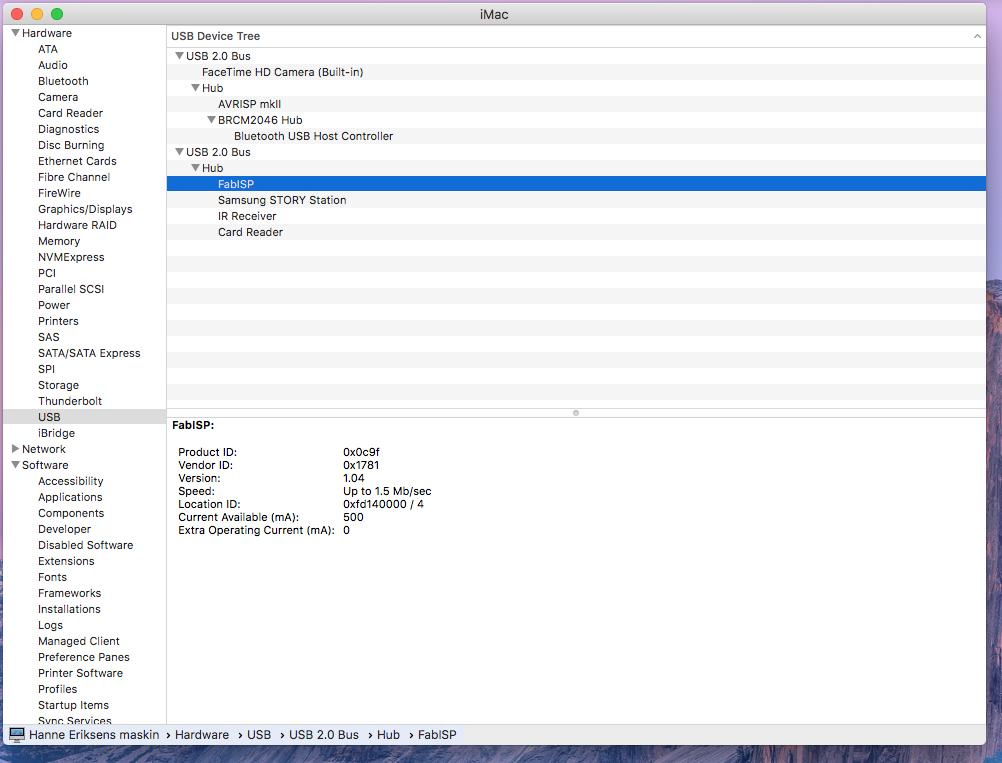
Debugging
I had a real challenge to get my FabISP to show up on my Mac. The only error that came up was when I tried to program the FabISP.
The error is the line:
"main.c:88:13: warning: always_inline function might not be inlinable [-Wattributes]"
I tried googled it, and it came up several cases where students using Mac had experienced this - but none of them had a solution and it seemed like it worked anyway.
I spent a whole day trying different debugging, and I think the mix of going over the soldering, re-starting my computer and keep trying to program it solved it in the end.
I did still get the error - but the final message says "Fuses OK" - and the controller was finally showing (after another re-start).
!!!!Remember to remove the soldering blob after you have programmed the board!