#WEEK3
COMPUTER CONTROLLED CUTTING
This weeks assignment:
Make lasercutter test part(s), varying slot dimensions using parametric functions, testing your laser kerf & cutting settings (group project)
Cut something on the vinylcutter
Design, make, and document a parametric press-fit construction kit, accounting for the lasercutter kerf, which can be assembled in multiple ways
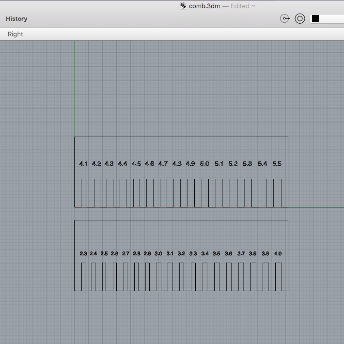
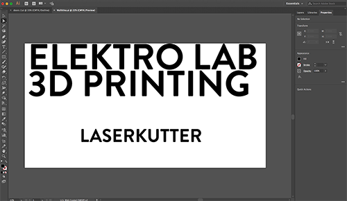
The design was made in Rhino
Exported to AI file and sendt to the
laserkutter
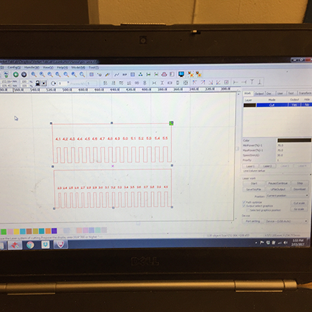
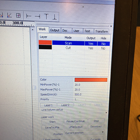
The settings were set in the lasercutter software RDWorks
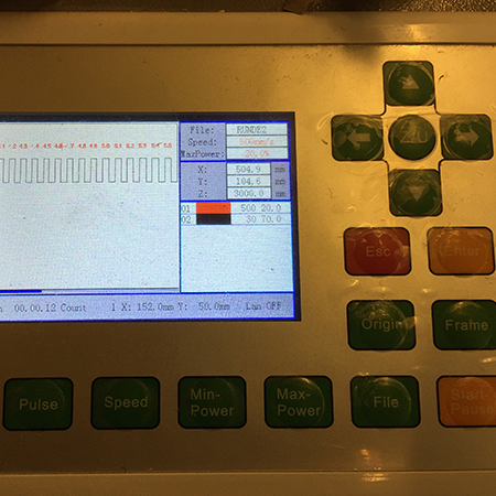
And then sendt to the lasercutter
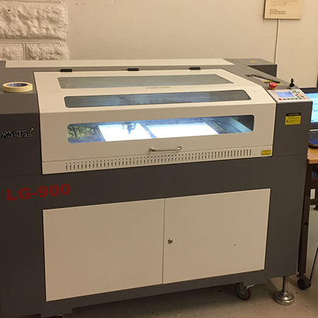
The type of lasercutter that we use is:
G.Weike LG-900
With the spesifications:
Laser- type
Sealed CO2 laser tube
Laser power
100W
Engraving area
900 x600mm
Whole machine size
1,360 x 1,010 x 1,070mm
Engraving speed
0 - 60,000mm/min
Resetting positioning accuracy
±0.05mm
Working voltage
AC 110 - 220V±10%, 50 - 60Hz
Gross power
<1,000W
Minimum shaping character
English 1 x 1mm
Graphic format supported
BMP,PLT, DST, DXF, and AI
Driving system
stepper
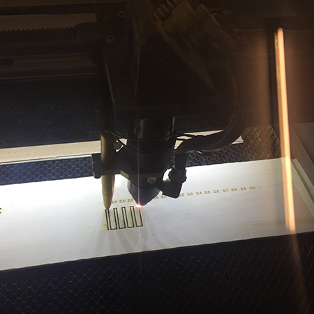
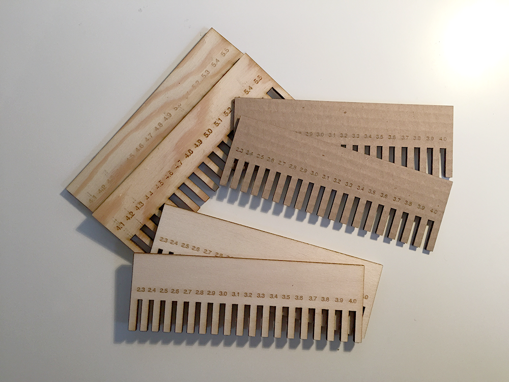
And the combs were made of 3 different types of wood and cardboard
Final result
Lasercutter
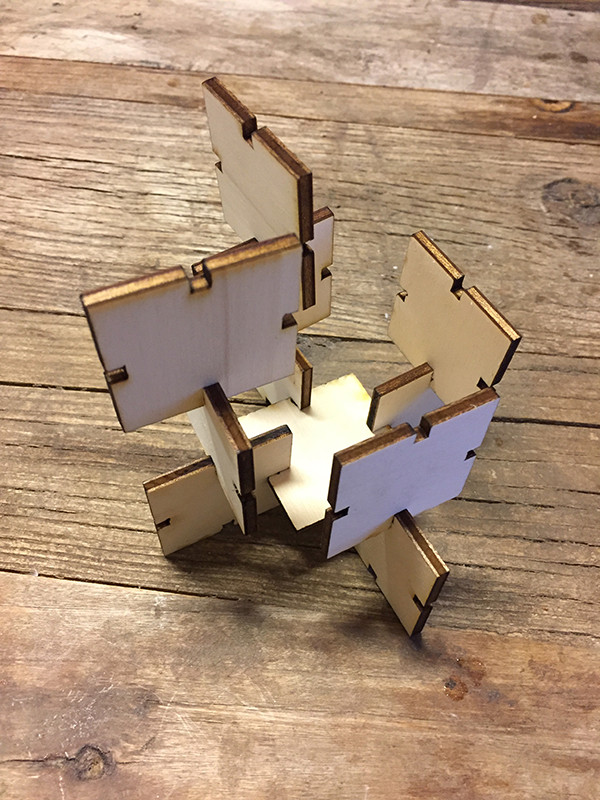
"Construction kit"
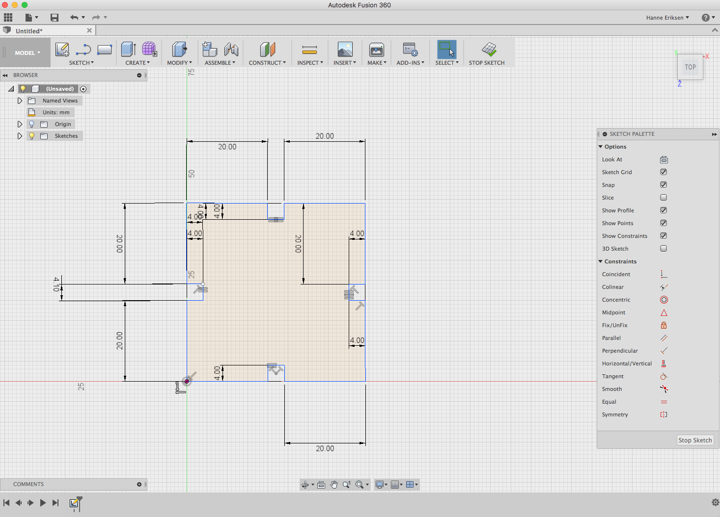
For the contruction kit, I put together a basic shape in Fusion360, where I tested the parametric function for the material slots.
Designing something using parametrics means to use a constraint systems which solve a set of continuous and discrete constraints. For example, using paramterics when working with the same shape - but for different thickness of materials, means that you can separately choose to change only the measures of the material and keep the rest of the shape as it is. In Fusion360, this is easily done by using the the constraints functions. It this model I chose to use the function "Equal".
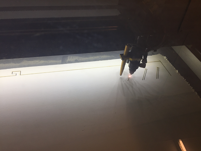
After modelling it, I then went on to export it as a PDF and opening it in Illustrator to save it as a Illustrator file, since the lasercutter do not accept PDF format. I have connected all the PC's that is connected to the machines to dropbox, so I saved the AI file directly into Dropbox, and imported the file into RDWorks program on the PC that is connected to the laser. RDWorks is where I set the settings for the lasercutter job.
The Pressfit kit was lasercut on 3.6mm plywood, using 70% power and 30% speed.
I have later found out that by right clicking on the sketch - you get the option to save the sketch as a DXF file directly (which the lasercutter reads).
Lessons learned
The lesson I learned from the group project where we made the "combs" was that, first off all, you can not rely in the "given" thickness of the material. You should always measure the actual widht. By making a pressfit test, you find the perfect fit for the object that you are designing. Depending on wether is should be a "tight fit" that has the goal to stay in place, or a loose fit to be able to take it a part easily.
Lasercutter
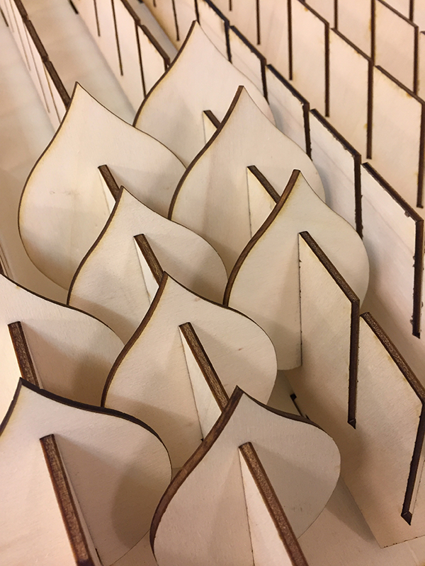
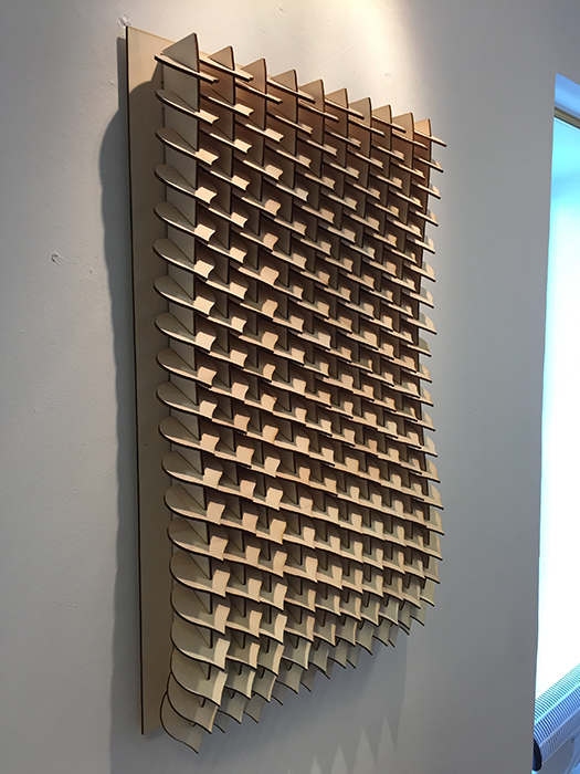
"Wall piece - parametric design"
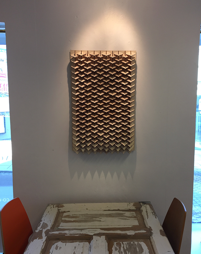
For the project of making something with parametric design, I wanted to make something visually interesting, that would work as a nice showpiece for using parametric design when working with lasercutter. I ended up with designing a wall piece with an organic shape that also gives a rigid systematically impression.
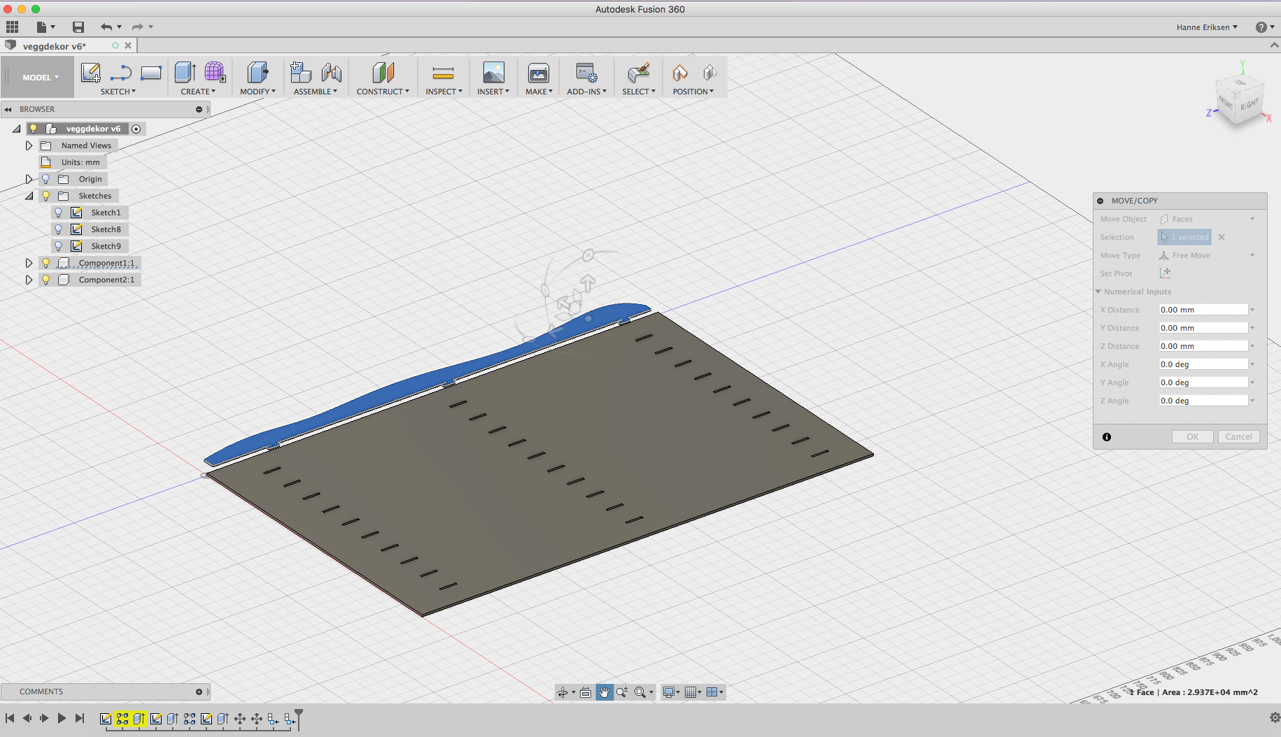
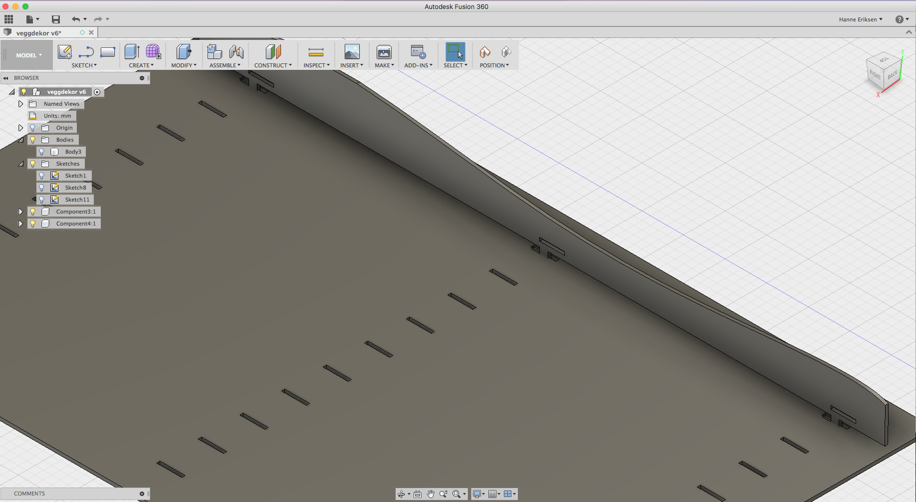
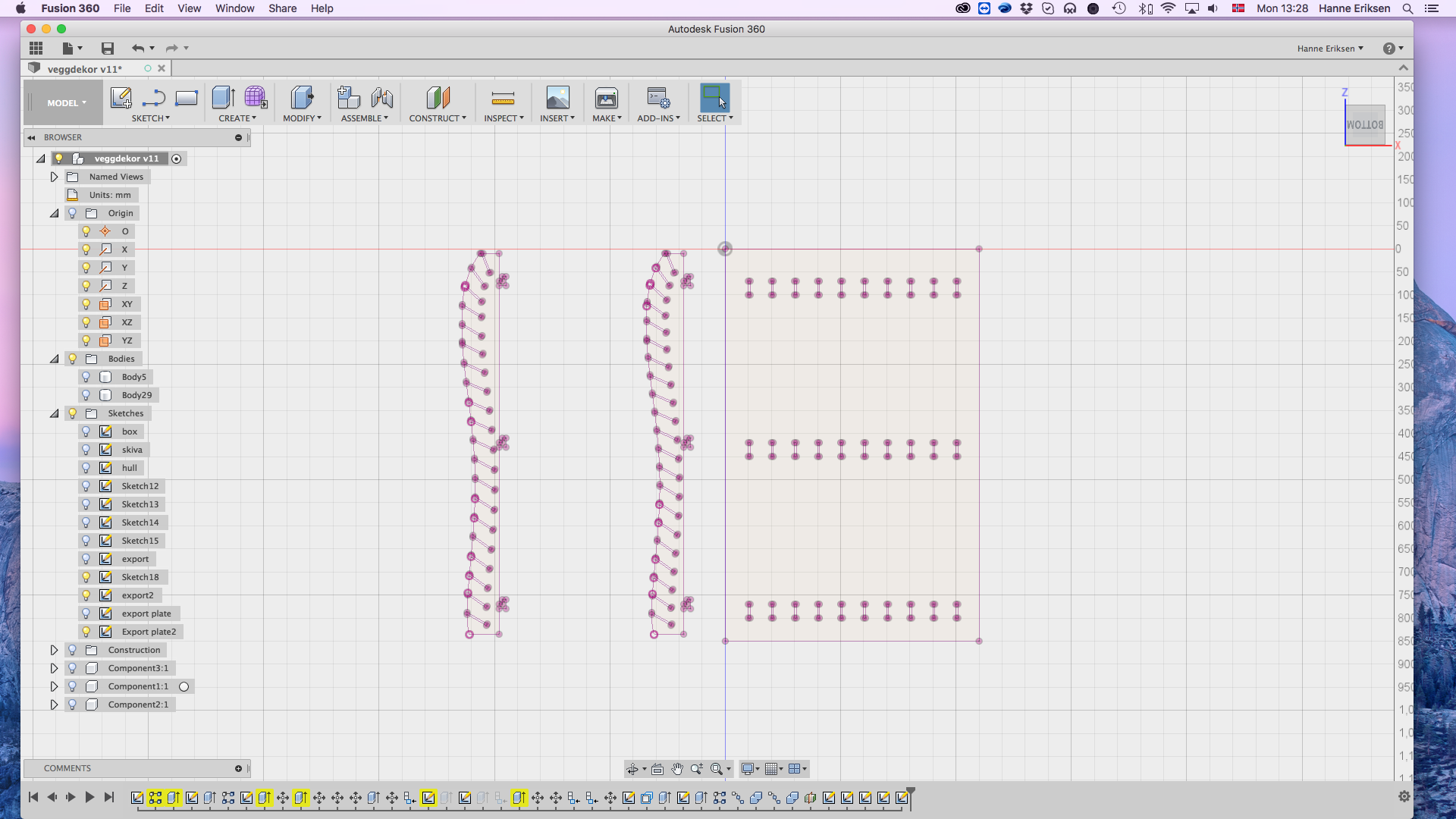
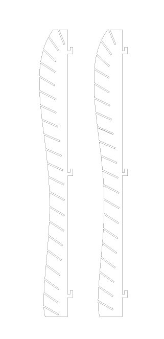
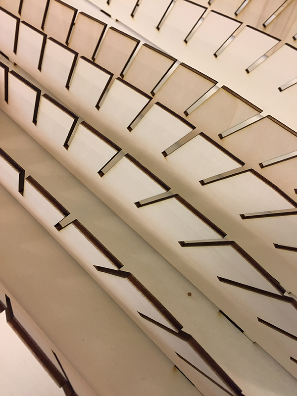
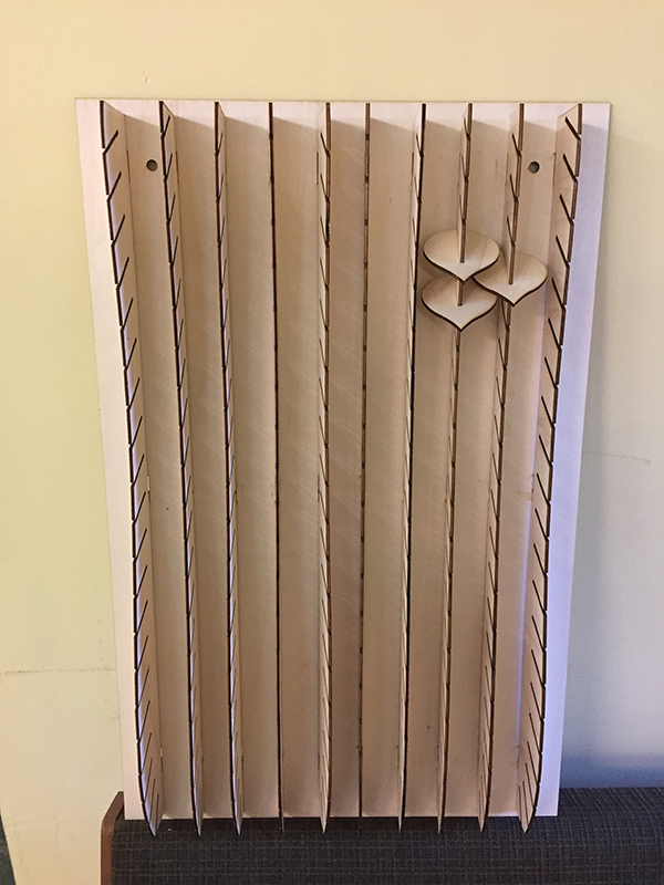
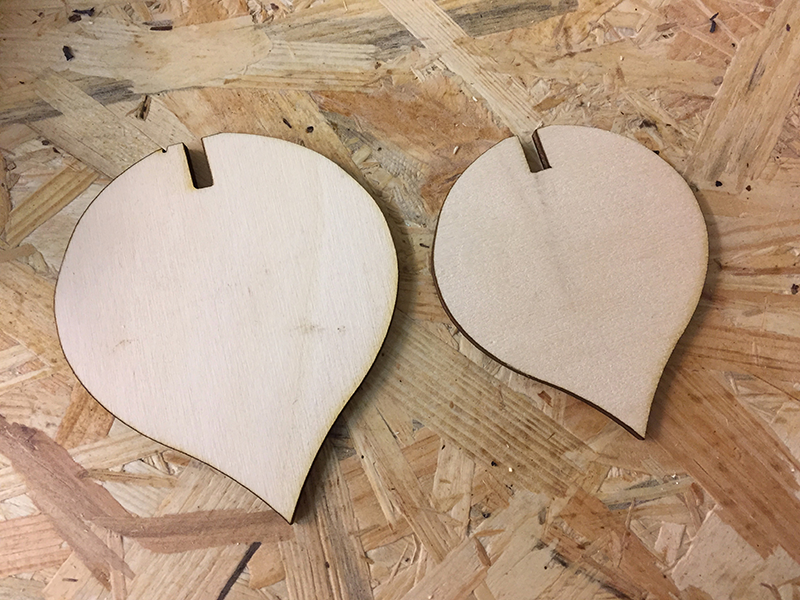
I designed the wall piece with parametric design in Fusion 360. Since I am totally new to this program - I end up using this to learn it more thorough. The pattern function in Fusion became especially handy in this design. Making it easier to space out and place the slots out evenly. But, when it was time to make the second vertical piece to alternate the design - I ended up having to use Illustrator in the end to be able to finalize the project in time. Since the vertical elements had to have the slots place unevenly for the leaves to fit - I had to export the element to Illustrator and make a copy where I moved the slots to fit in between the others. This worked out perfectly. For the last element - the leaf - I made three different tries before I found the perfect fit and size for the piece.
As a final touch - I might even put some lights in between, which should add a nice effect to it.
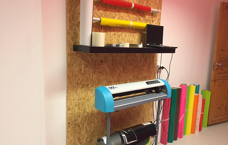
Vinylcutter
"Signage for the lab - using GCC vinylcutter and Illustrator"
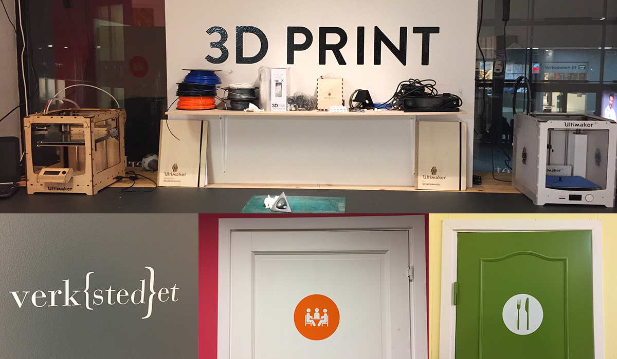
For the vinyl cutting part, I needed to get som signage done for the lab - so I ended up putting up these
different ones for the different rooms and areas. The text on the walls, and the "Verkstedet" logo is my own design. The other icons was only resized and placed inside of the circle to get a boundary that fitted with the doors.
The software I used for this was Illustrator - which is the best program to work with illustrations. I have worked with vinyl
cutting before, in one of my previous jobs - so this project went quite nicely without much challenges.
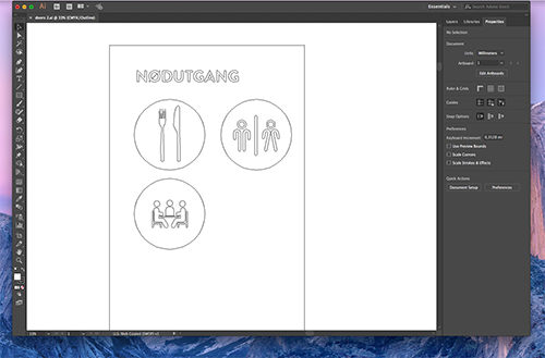
When create 2D design, I have started to mainly work in the outline view of the program, so I will not get confused with the infill and other invisible lines. The illustrations are a mix of free vector icon from http://www.flaticon.com and com
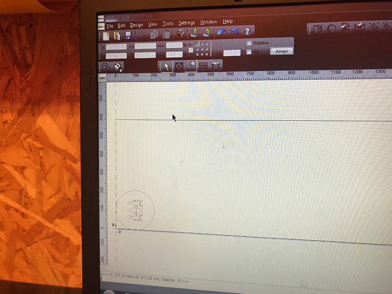
I saved the files as AI, and I imported the design in the software Great Cut - which is the software for the vinyl
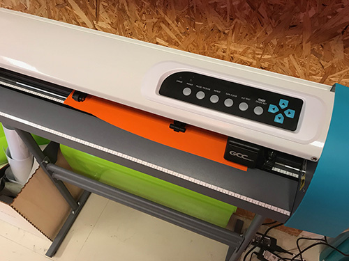
cutter. I then found a piece of oranged colored vinyl that I placed in the feeder of the cutter.
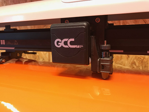
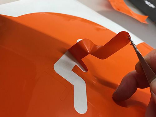
The vinyl was cut on a GCC24 vinyl cutter. The vinyl is cut out with a small knife that rotates after the vector lines. After cutting the file, I then cleaned up the material by removing the vinyl with a pair of tweezer that I did not want on the final result.
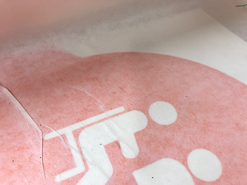
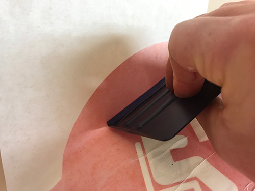
After cleaning up the vinyl, I put on the application tape - for mounting it on the door. Final - I stuck the vinyl with the application tape on the door - removed half of the backside of the vinyl, and started transferring the vinyl onto the door.