Assignment
Make an in-circuit programmer by milling the PCB, then optionally trying other processes
Produce FabISP board
FabISP Programming
Machines
Trotec Speedy 100
Milling CNC
Soldering Heat Gun
Software
Adobe Illustrator CS6
Arduino
Job Control
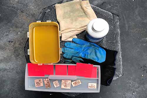
Materials
Antistatic table, Tweezers,
Solder Paste, 1/32 Milling Cutter,
Copper Board, Ferric Perchloride,
Solvent, Spray Paint
Electronic Components
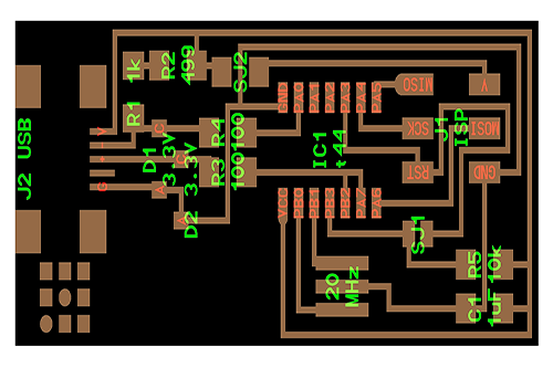
1 ATTiny 44 microcontroller, 1 Capacitor 1uF,
2 Capacitor 10 pF, 2 Resistor 100 ohm,
1 Resistor 499 ohm, 1 Resistor 1K ohm,
1 Resistor 10K, one 6 pin header,
1 USB connector, 2 jumpers,
1 Crystal 20MHz, 2 Zener Diode 3.3 V,
1 usb mini cable, 1 ribbon cable,
two 6 pin connectors
Workflow
1. Know, Learn and Classify electronic components
2. PCB with Laser CO2
3. Cleaning and Etching
4. Soldering
5. Programming
Know, Learn and Classify electronic components
Being the first experience with electronics, I received support from my colleagues at Fab Academy in El Salvador.
They were experimenting with various ways of producing PCBs. The advantage I had is that they took me by the most direct route. That was fundamental because I was able to advance with the production of my FabISP.
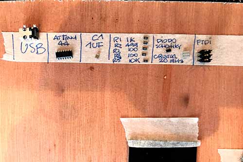
The first step was to know all the components that FabISP carries, it is very important to order all the materials and components that will be used in production, I learned that you have to have a lot of order and pay attention to the reduced scale with which you have to work.
In the process of learning-doing it is very important to have good advice, an adequate space with lighting and a pleasant atmosphere, especially having good friends to support you with this hard task when it comes to your first time. Thanks to Ivan, Damaris and Kako from El Salvador.
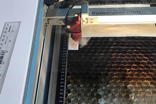
PCB with Laser CO2
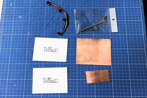
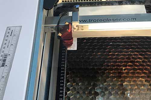
I started preparing the materials to work with the laser cutter.
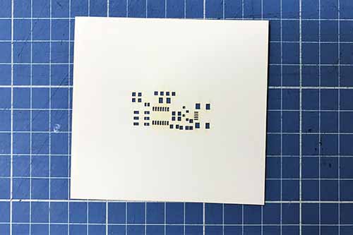
The first thing was to cut some stencils with the pads and then use them in the welding process. In this process take advantage of advance work for the following assignments and work on the PCBs that we will use at the Fab Academy.
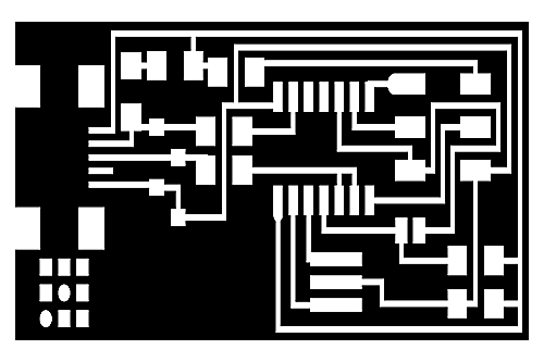
Second, we reviewed the traces and the boards, downloaded the files of the class of Electronics Production, I decided to use hello.ISP.44.res.cad. Having the files I exported them to Adobe Illustrator to work with the vectors and prepare the file to be able to cut with the laser on the copper board.
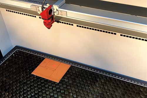
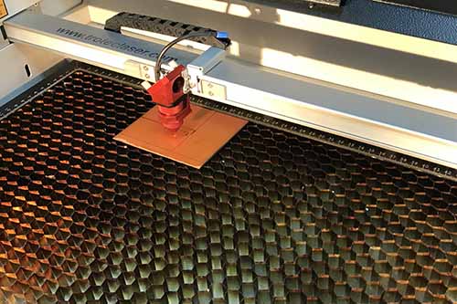
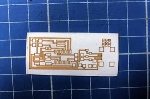
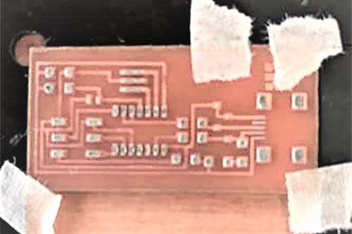
Third, with the copper plate of the FabISP, I glued a vinyl with adhesive, excellent to work PCB's neither much nor little glue to avoid harming the copper board. And with this we cut the traces and pads of the board. It is excellent because then you can lift the adhesive very easy, only with the help of a pair of clamps and the work is fantastic.
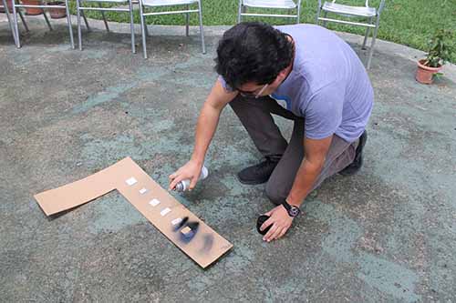
Fourth, with traces and pads free now it is very easy to use a spray with black paint to mark enough. In this process I had to try several times until I get the paint will be well enough adhered, without excess and without running under the adhesive vinyl.
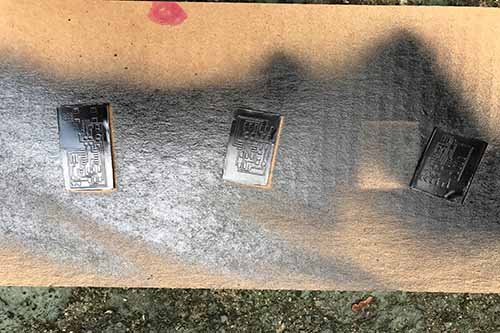
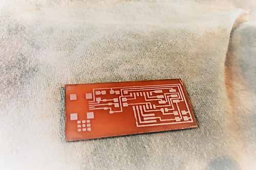
Cleaning and Etching
With the process of production in the laser facilitated to a great extent the cleaning of the copper board, only with remover, a little of cotton and the board was ready.
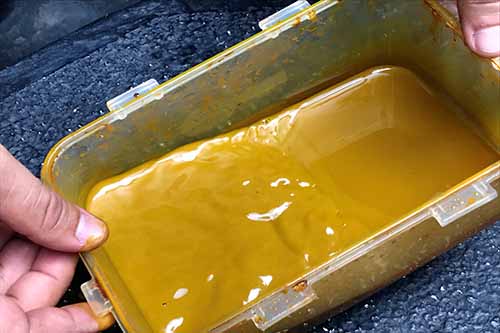
The next step is to remove the copper from the board, so that only traces and pads remain. For this I used Ferric Perchloride, with great caution I submerged the board and after 10 minutes had the board ready to continue.
It was extremely interesting to learn this process, as the exchange between the Copper Board and Ferric Perchloride leaves everything ready for there to be continuity between the electronic components.
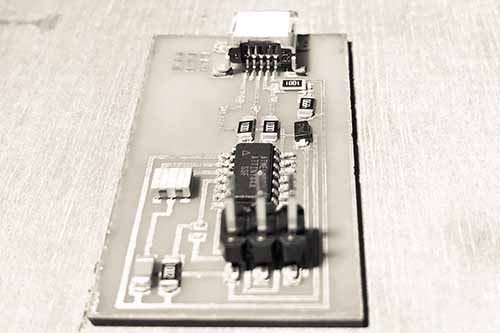
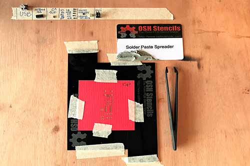
Soldering
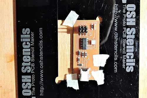
To solder the board first i fixed them, then i use a stencil to apply a solder paste; the stencil only have to have the spots where the pins of the elements are going to be solded, and i have to apply it with a plastic card making sure to cover all the holes, could repeat this process the times you needed, inclusive change the stencil if necessary because i punch the holes in cardstock with the same laser cutter that use for engraving.
When finish to apply the soldering paste, i have to place all the components carefuly, as almost all the necessary components are tiny, this was the part that toke more time, i had to be carefuly with the diodes becouse they have polarity, and with ATTiny 44 because is sensible to electrostatic. To manipulate components i used a pair of anti-static tweezers.
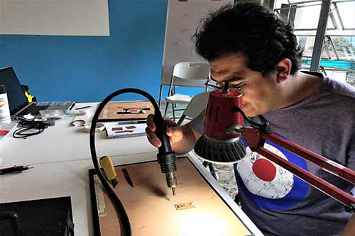
After finished to place all the components, i used a heat gun the welding them, this machine blows hot air and makes the soldering paste melt fixing the components to the board and allows the electrical conduction among them.
And finally have to check all the connections, and if everything is alright, it is only needed to clean the board with contact cleaner and it’s ready to be programed.
Programming
For windows we have to follow this steps:
Run Cygwin setup, click next until a list appears
Look for MAKE, click on DEVEL and select "make: The GNU version of the 'make' utility" and click next and install
Search the location of avrdude.exe , I found it on Arduino\hardware\tools\avr\bin, copy the folder root
Open System Properties, on the "Computer name, domain and workgroup settings" select Change Settings
Go to Advance tab and select Enviroment Variables
On the second list look for Path, click it and select Edit...
Select New and paste the folder root where is avrdude.exe and Accept to all the windows
Download firmware.zip next on this section
Open Makefile on fabISP_mac0.8.2_firmware folder with a text editor
Make sure to change this lines with your especifications and save, this are mines:
DEVICE = attiny44 F_CPU = 200000000 AVRDUDE = avrdude -c avrisp -P COM3 -p $(DEVICE) -b 19200
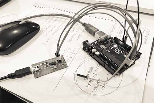
Open Arduino, go to File > Examples > ArduinoISP
Upload the sketch to your Arduino
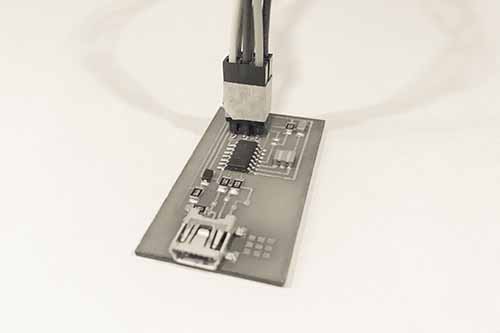
Read the skecth and look for which are MISO, MOSI and SCK pin on your Arduino and connect with the respective MISO, MOSI and SCK pin on your FabISP
Open Cygwin Terminal, write cd cygdrive and then change directory - cd until you get where you have the Makefile
Write make fuses and Enter
Write make flash and Enter
Now your FabISP is programmed!!! and you have to remove all the jumpers of the board